 Sergej Stoetzer
Overview
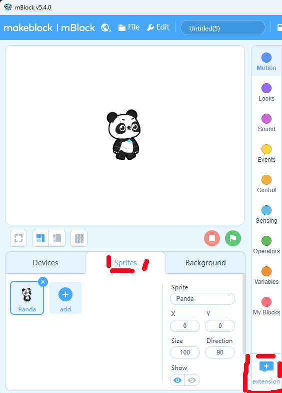
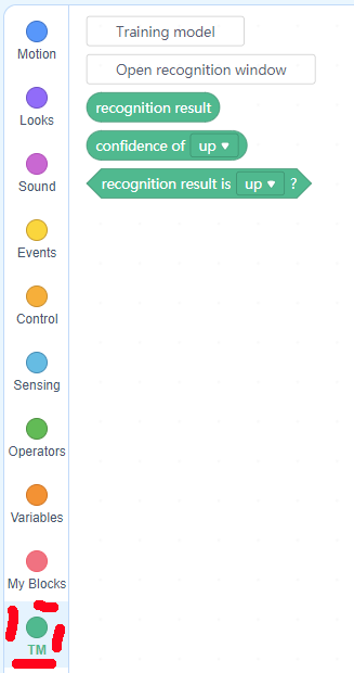
This project shows how to build and use a simple and inexpensive eyetracker - primary school students (starting age 9 ) can build and use it in Scratch3 (block-based coding) environments.
It can also be extended to a sophisticated version involving 3D printing and soldering - for secondary school students, and be used with OpenCV and Python coding.
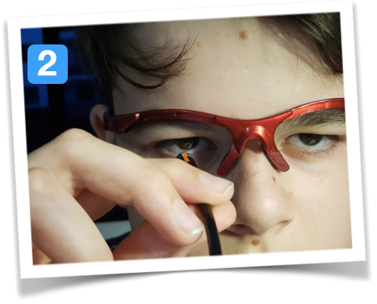
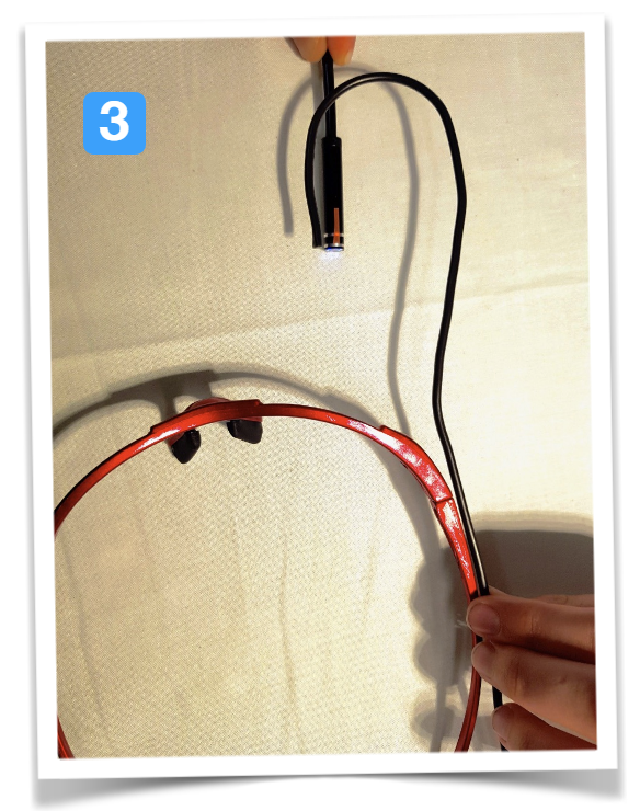
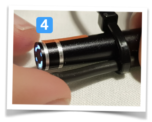
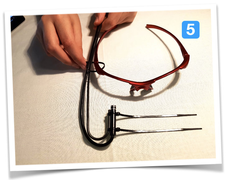
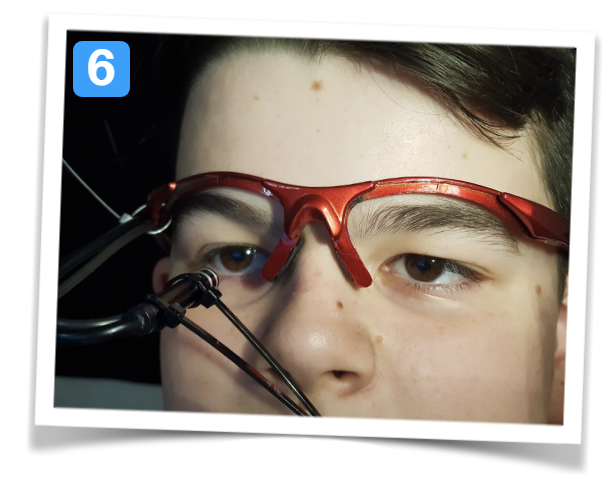
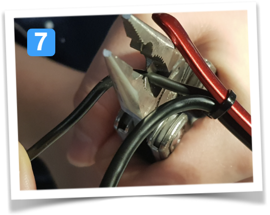
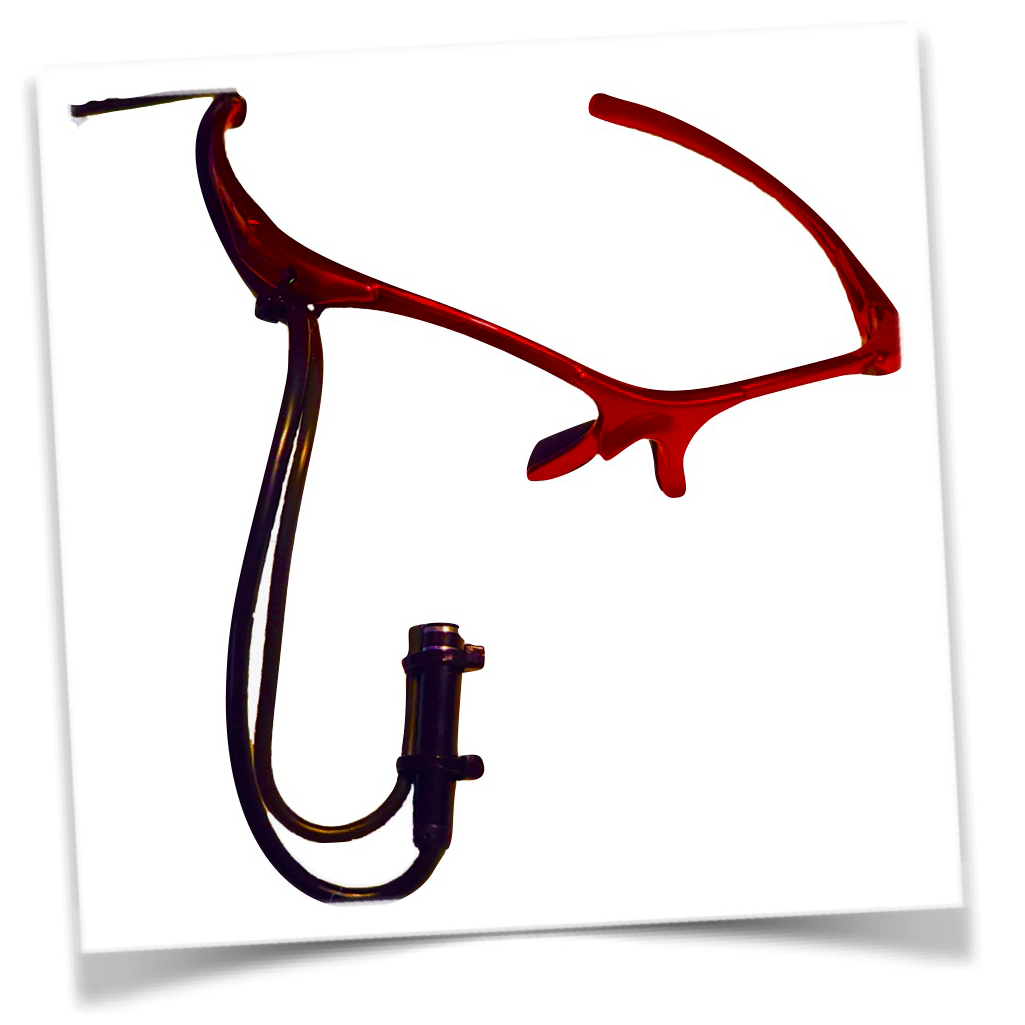
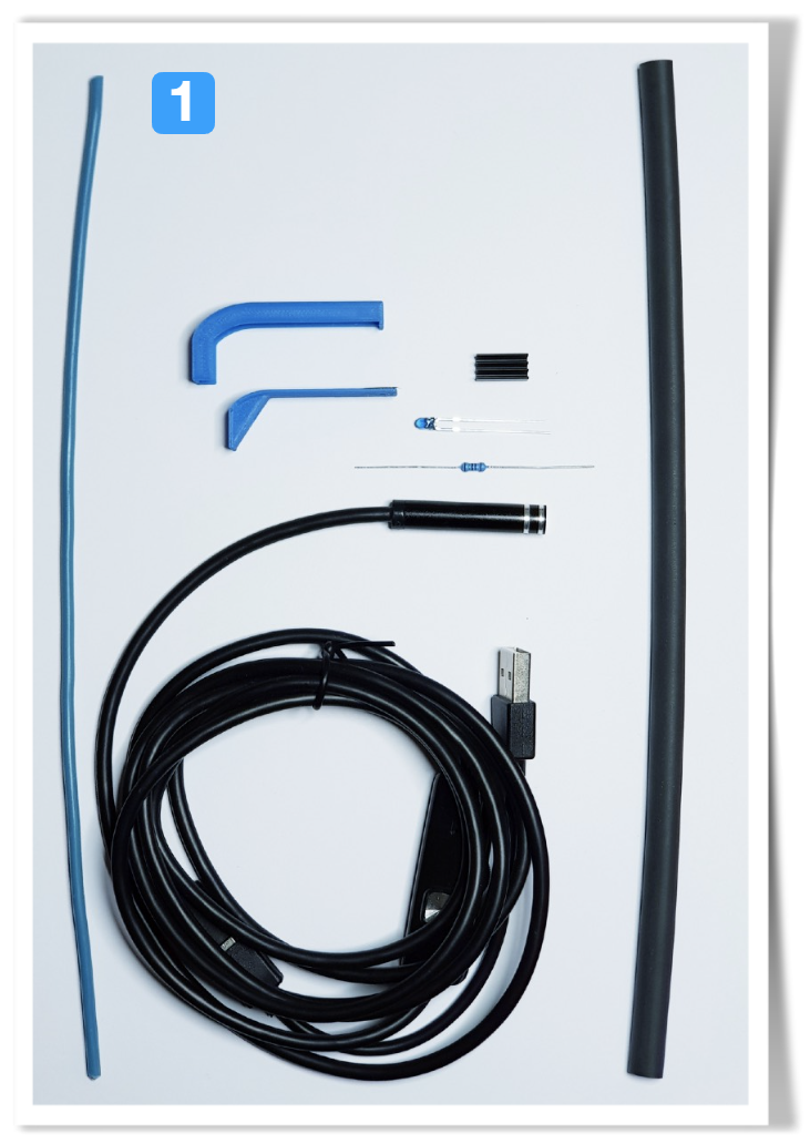
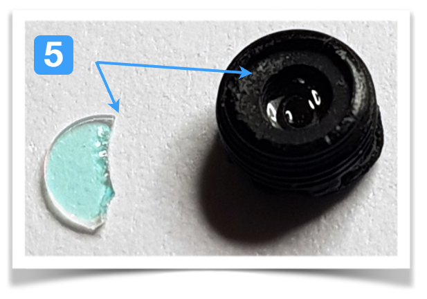
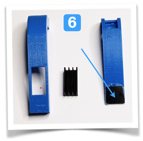
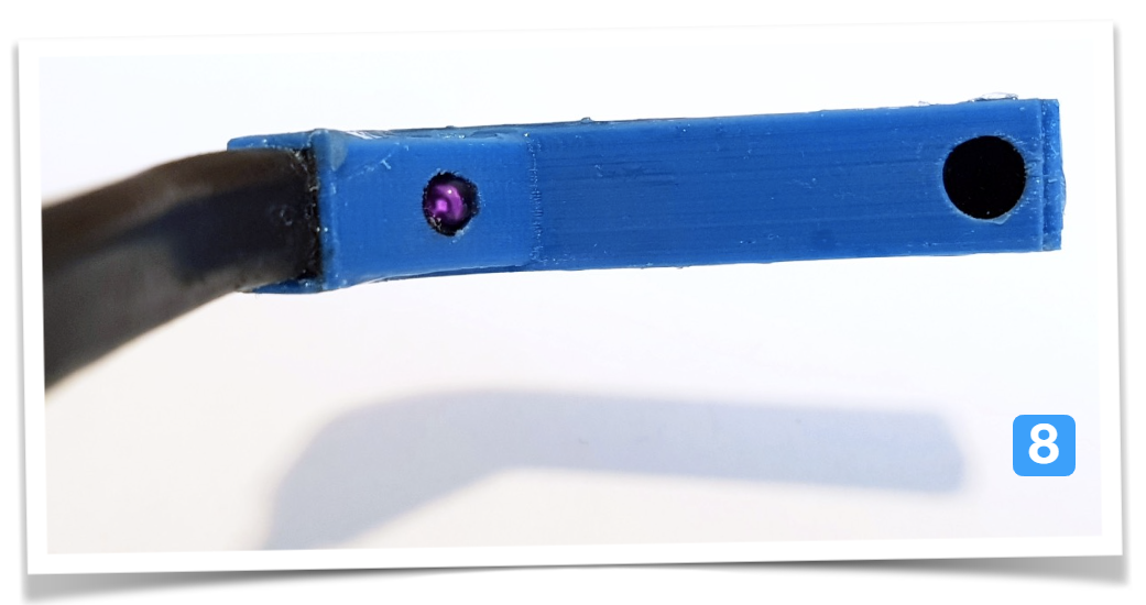
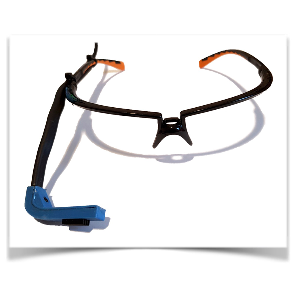
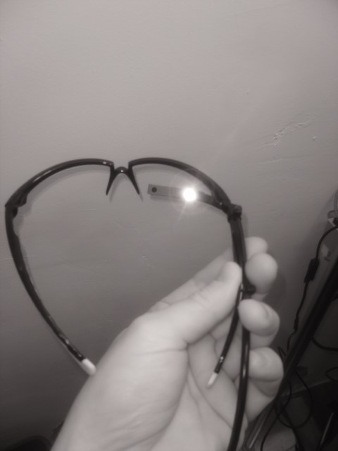
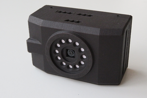
It uses a cheap endoscope USB camera and a frame from a security camera. For the advanced version, IR illumination is added, the IR-blocking filter is removed from the small camera and everything is mounted inside a small frame.
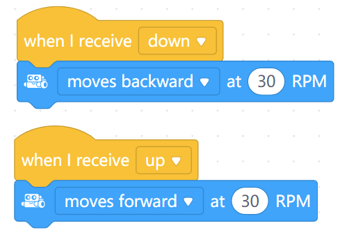
The project also covers how to use this build to control real robots, so students can build (simulate) medical support like wheelchairs or control a computer with their gaze.
Background
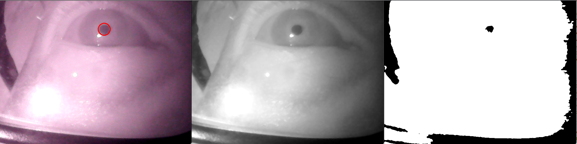
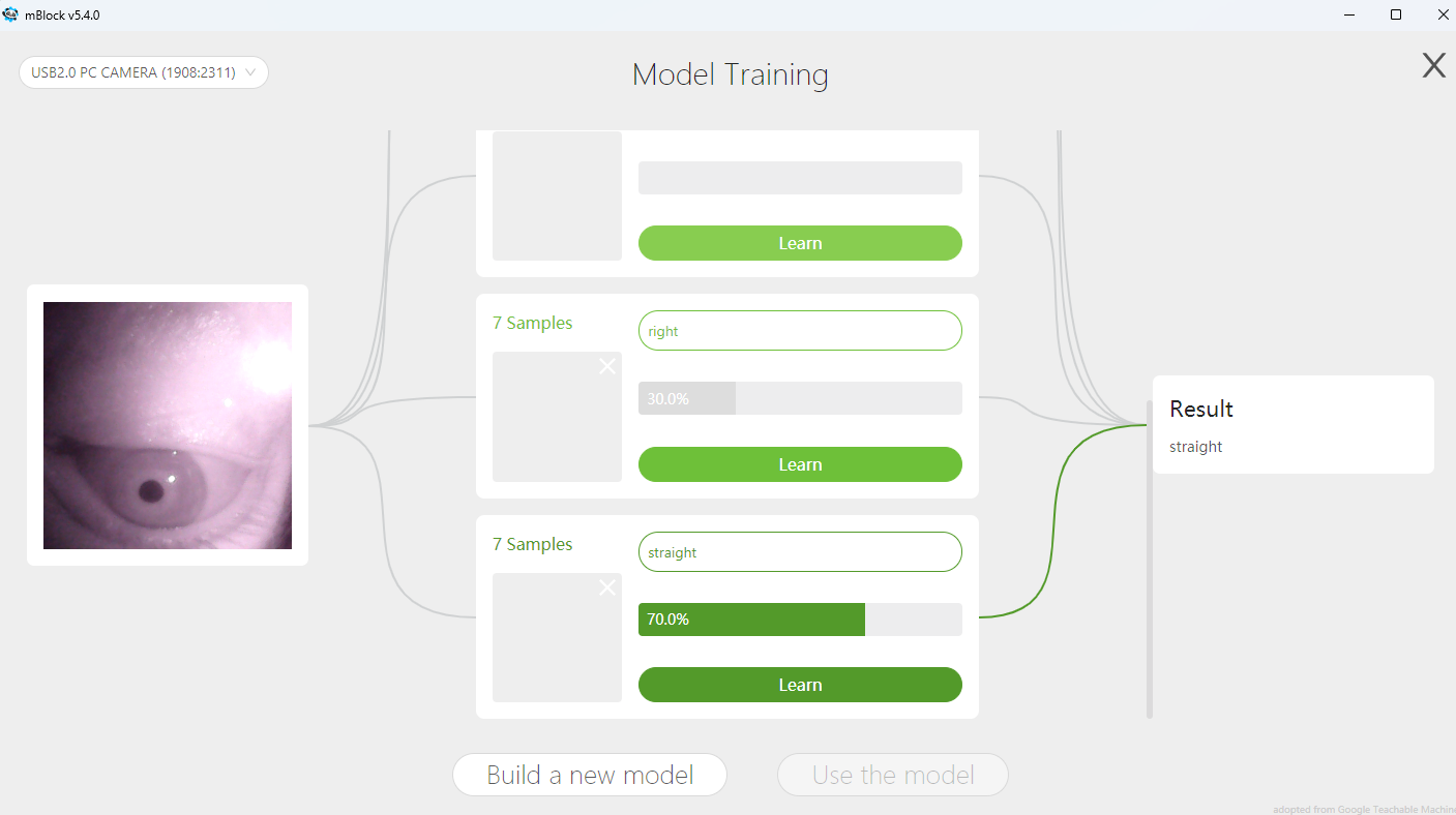
Eye trackers observe the eye with a camera and record the movements of the eyeball and the blinking of the eyelids. Contrary to our everyday perception, this movement occurs erratically (saccades), and only in the moments when a point is fixed a conscious perception can take place.
The sequence in which individual elements of a picture or a real-world scene are viewed and the duration with which they are viewed provide important clues to their meaning and the processing of information in the brain. The evaluation of the eye position is automated. High-quality, professional systems for research applications can often record both eyes simultaneously and offer a high sampling rate (>60fps) so that even fast movements can be recorded. The range of possible applications is correspondingly large and extends from medical topics to information processing of stimuli to simpler marketing studies and optimization of websites, advertising spaces, and product presentations.
The possibilities presented in this tutorial for building one's own eye tracker and using it for projects do not achieve the high sampling rate as professional ones (maybe up to 30 fps), but are easy for pupils to replicate and can also be used in their own programs. For example, games or robots can be controlled with graphical programming in Scratch - or you can use openCV for more sophisticated projects.


 Pascal Buerger
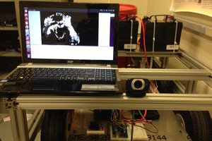
 Tom Quartararo
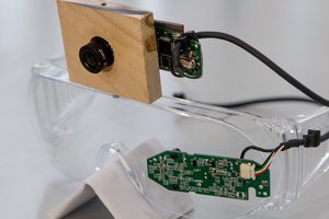
 John Evans
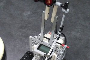
 vcarter0