 Trevor R.H. Clarke
NOTE: This post contains sponsored content.
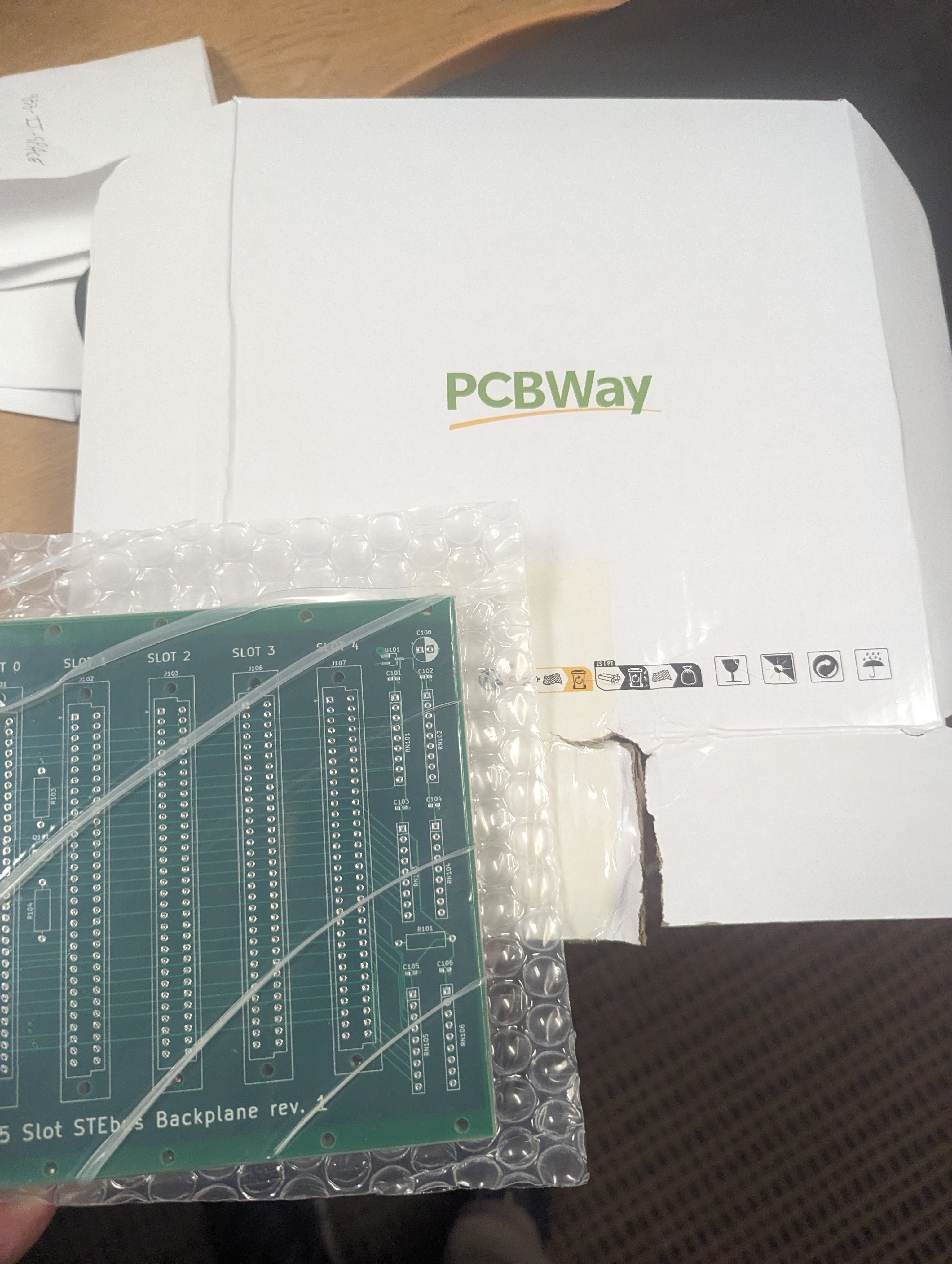
I finished rev 1 of a 5 slot backplane and sent it to PCBWay who were kind enough to send me some free boards to try out in exchange for a review of the service. Check out the end of this post for info on how they turned out.
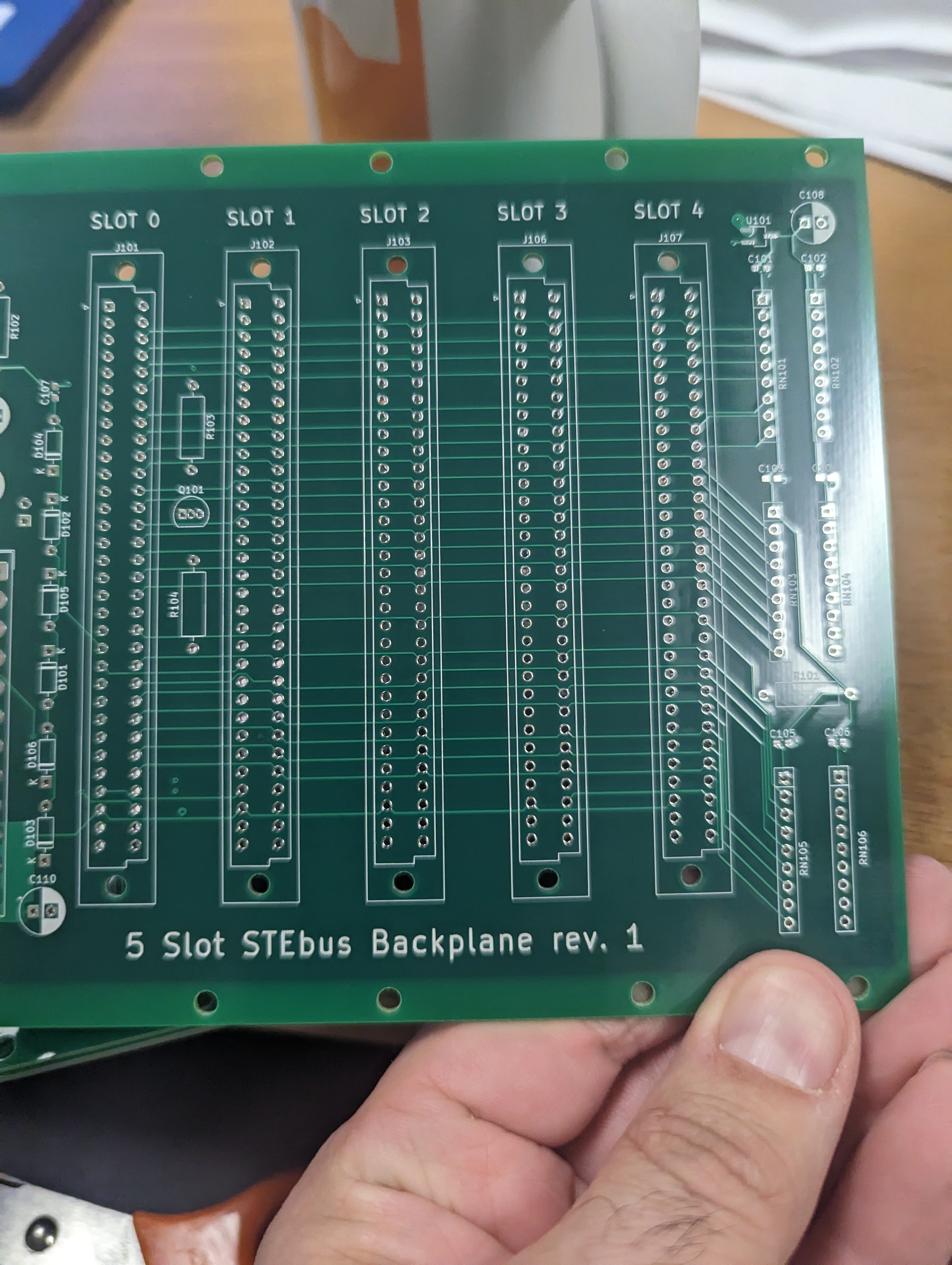
This is a simple 5 slot backplane with active termination. Follow along with the schematic while I describe the design.
I decided to use an ATX-24 connector to support an ATX power supply since these are very common and fairly inexpensive for multiple power rails. The 3.3v isn't used but the +12v, -12v, and +5v rails provide power for the STEbus rails. The caveat is that the ATX standard defines a looser standard for voltage stability on the +/-12V rails than the requirements for STEBus so the rails may not be compliant. STEBus requires +/-5% and 50mV pk-pk ripple on all rails and -2.5% on the +5V rail. ATX only requires +/-10% on the -12V rail and 120mV pk-pk ripple on the +/-12V rails. In reality, these are the worst case specifications and most ATX supplies will be more stable and have less ripple. Also, a lot of STEBus cards should also work fine with the looser specifications with the possible exception of DAC/ADC cards and the like. The ripple can be further mitigated with more filtering and bigger caps on the backplane or boards. This should also help with voltage drop on the -12V rail. In short, there should be no problem getting a mostly digital hobbyist system running with an ATX power supply.
ATX power supplies use hard and soft switches for power. The backplane includes a header (J104) to accommodate a soft switch but this can be bridge with a jumper or solder bridge to force the soft switch closed. In addition, an ATX supply has a +5VSB rail which is a 5V rail with lower current capability and looser stability requirements. It's meant to supply power to circuits used for the soft power capability and some other standby capabilities like status LEDs. We can tie it to VSTBY on the STEBus and treat it like a battery. This allows us to simulate a power fail by turning off the supply with a soft switch. The full system can be turned off with the hard switch on the power supply. There's a jumper pad (JP102) to tie VSTBY to either +5V or +5VSB.
The other jumper (JP101) ties the PWR_OK line on the ATX supply to ATNRQ0. It is pulled low after power is turned on to give it time to stabilize. It can be used to trigger a power failure interrupt on the line suggested by the STEBus spec. After looking at the schematic of rev 1 I believe there's an error. There's an inverter connected to the line to switch to inverted logic but re-reading the ATX spec I think this is already inverted logic so if you use this revision you might not need to populate Q101, R103, and R104 and jumper JP101 pin 2 directly to Q101 pin 3. If this is the case I'll put out rev 2. Another change that might be worthwhile for rev 2 is the ability to jumper PWR_OK directly to the System Controller board so it can be used to manage SYSRST on startup. Stay tuned for updates.
Bus termination is based on the IEEE-1000 §7.7 Termination Networks. The circuit is verbatim from Figure B.1 Bus Terminology Arrangement with component types chosen from jelly bean parts. A 1N4148 silicon diode and some SD103C Schottky diodes. You should be able to substitute any of these with just about any diodes you have on-hand provided they can handle the current. The 2.8V needed for termination is created with an RT9080 LDO regulator. I happen to have some around from another project and they are more than capable of providing a stable 2.8V. Similar devices should work ok if you have something around but YMMV.
The boards arrived from PCBWay in a timely manner and they were very well packaged.
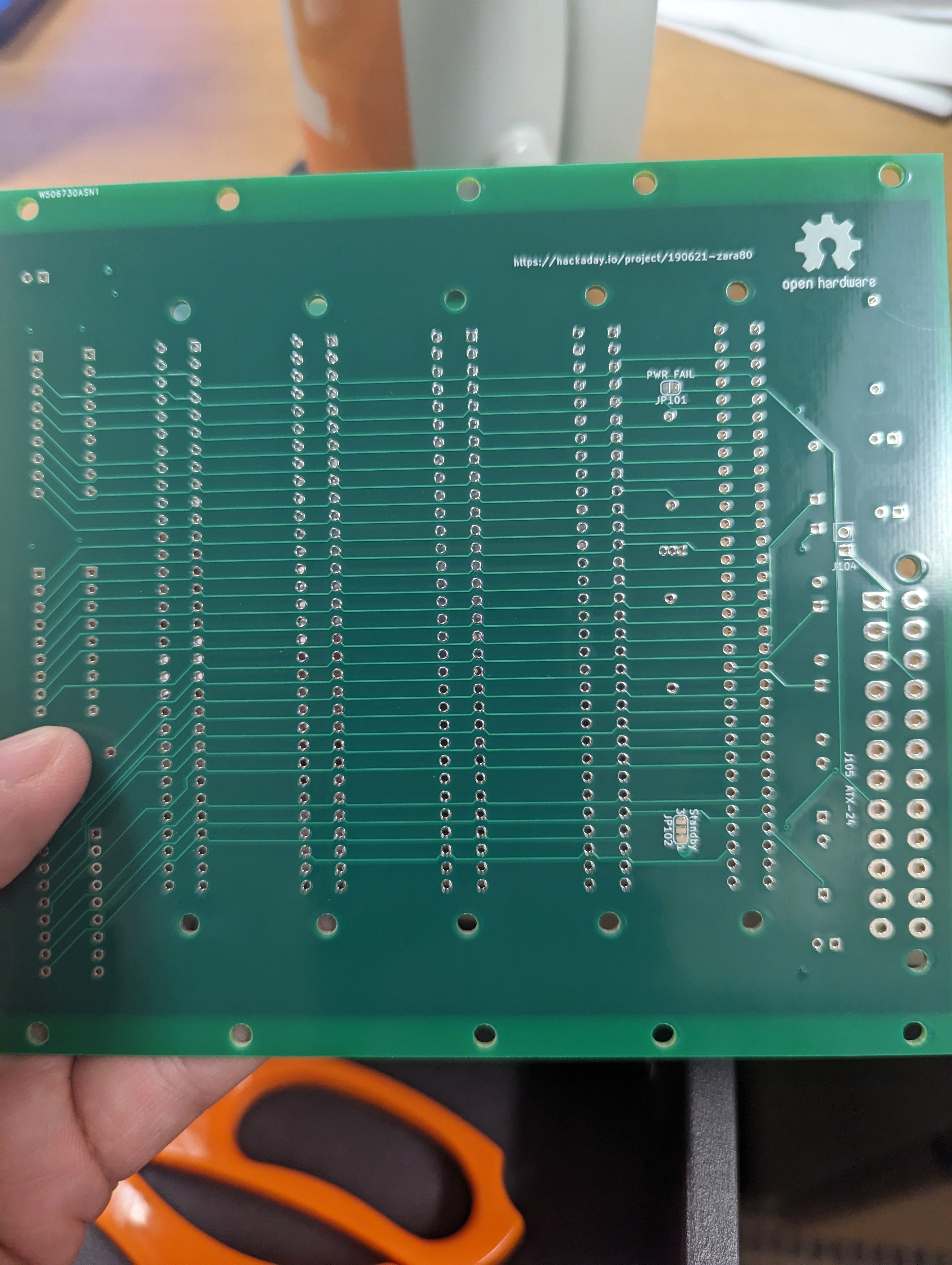
The layout is fairly simple, rev 1 gerbers are available in the github repo. Once I've tested everything, I'll release them here as well. The cost was a bit more than I'd pay at some other PCB proto services but the number of options available for impedance controlled boards and other advanced options is quite a bit larger than those other services and the quality seems to be at least as good as, or better than the others I've used. I'm pretty happy with the boards and I'll definitely use PCBWay again, at least for my HAM radio projects that require impedance control. I'll be ordering the rest of the boards for this project as well.
Discussions
Become a Hackaday.io Member
Create an account to leave a comment. Already have an account? Log In.
The bus termination regulator needs to be bidirectional - it must pull down the rail when the rail tries to exceed 2.8 volts. This absorbs overshoot from reflections and ringing. Normal regulators are not designed to do this. It needs to be fairly beefy to pull up 32 signals with big current transients. The RT9080 looks too small. See:
https://hackaday.io/project/178391/gallery#c902421ad254c608dfb46a833185718a
which uses a couple of TO-220 power transistors.
Are you sure? yes | no
You are right. The spec does say VSTBY is 5V +/- 5%. I notice one CMOS memory board design optionally allows the battery to power this pin for battery backup. This voltage was meant for backing up CMOS RAM etc. Some chips don't go into low-power mode if VCC is a healthy 5V. The Hitachi H8 would continue to drain power at 3V6 and not stop until about 2V7. So a 3V6 NiMH battery did not last long. A 2V4 battery was perfect.
Are you sure? yes | no
The +/-12V rails were primarily for RS232 buffers, I never saw them used for anything else. 10% should be fine if the buffers are okay with it. More concerned that some PC PSUs need a minimum load, and a couple of modern boards with CMOS RAM etc. might not provide it. Glad to help if you need any PAL chips programming.
Are you sure? yes | no
What housing are you planning for? I just started looking into STEbus instead of RC2014 or a homegrown, and like that you're using an ATX PSU so may copy your design!
Are you sure? yes | no