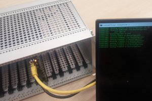
• 5 Slot STEbus Backplane rev 1

    Trevor R.H. Clarke05/01/2023 at 03:01 4 comments

    NOTE: This post contains sponsored content.

    I finished rev 1 of a 5 slot backplane and sent it to PCBWay who were kind enough to send me some free boards to try out in exchange for a review of the service. Check out the end of this post for info on how they turned out.

    Read more »

  • Finalized on Bus

    Trevor R.H. Clarke04/26/2023 at 16:23 0 comments

    I began laying out my modified RC2014 bus and I realized it has more problems than just missing signals. There's not termination, layout is not friendly to cross coupling concerns, etc. It's a great breakout for a z80 but it's a badly designed bus for a backplane based system so I'm entirely dropping it. However, I have a better solution.

    Read more »

  • RC2014+VW Bus

    Trevor R.H. Clarke04/17/2023 at 17:14 0 comments

    The bus I'm using is based on the RC2014 bus. It's primarily a break out for the Z80 pins with a few notable changes.

    The biggest change is the use of a JAE TX-24/25 connector instead of 2.54mm headers. The RC2014 boards suggest not using pins 40 and 80 as the resulting board would need to be longer than 100mm (the magic width for using the free version of some PCB design tools and the limit for super cheap proto boards from many manufacturers). These were used because  they are very easy to hand solder, most hobbyists have a bunch of them in junk boxes, and they are very inexpensive. I've decided to move to the TX-24 connector a it is 1.27mm pitch so 80 pins fit very easily on a 100mm board with plenty of room to expand with another connector if needed. They are keyed, shrouded, and click together leading to a fairly robust connection and can be plugged and unplugged a number of times. They are also fairly inexpensive at just over $2 per connector in lots of 10.

    The RC2014 extended bus does not connect pins 41-56 and uses them as a way to key the 2.54mm header connectors. My bus connects these to GND since they are already present, this should help with impedance and noise issues that can arise with longer runs of the RC2014 bus while remaining compatible with the pinout.

    There are a number of user pins reserved in the RC2014 bus. My bus uses 5 of the 8 to add some important strobes from the S-100 including pSTVAL, pSYNC, ERROR, POC, and INTA. These are defined as in the S-100 specification. Certain RC2014 boards use these for other signals causing incompatibilities but this is a problem with user defined signals regardless of their use. Care should be paid when adding other boards.

    I'm ignoring DMA and temporary master capabilities of the S-100 as well as 16-bit data transfers. If I decided to add this later, I'll likely utilize pins 41-57 or add a second connector to the bus.

    I haven't added additional power rails as the occasional +/-10v (for RS-232), etc. can be easily generated on-board with modern DC-DC converter chips. The RC2014 does not state, but assumes a regulated 5v rail which is reasonable for a small system. 5V LDO regulators (for example, the 1117) are cheap and easy to use to increasing the rail voltage and regulating on each board is not a bad idea. For now, I plan to add a footprint for a regulator but not populate it. If necessary, I can add the regulators and increase the rail voltage to 12v or so.

  • Introduction

    Trevor R.H. Clarke04/17/2023 at 16:28 0 comments

    This is a homebrew Z80 based retroish computer that I'm designing and building. This post provides some background on why I'm working on this project, how I got to the design, and what my end goals are.

    Read more »