Close
0%
0%

USB Power Delivery for Arduino

A comparator and few resistors turn your STM32 board into a PD analyzer or power sink.

Public Chat
Similar projects worth following
963 views
0 followers
Instead of using a dedicated controller IC to implement USB PD communication, we can take full advantage of a microcontroller. An inexpensive board like the STM32 Bluepill and a dual comparator (for level-shifting) gets you started.

This project shows the simple circuit and provides the required software for encoding and decoding USB PD messages and for interacting with a power supply. It comes with examples for a protocol analyzer, for implementing a trigger board etc. The software is easy to use as it is integrated into the Arduino framework and IDE, and as all timing-sensitive parts are run in interrupt handlers.

Even a beginner electronics hobbyist can quickly build the simple circuit consisting of dev board, a dual comparator, resistors and connectors. This is unless a more capable STM32 microcontroller with built-in comparators or USB PD Phy is used – then the circuit is even simpler.

The software so far supports four STM32 MCU / MCU families. They require different additional components:

STM32 FamilyMonitor ModePower Sink Mode
STM32 F1 family
Dual comparator, resistors
STM32 F4 familyDual comparator, resistorsDual comparator, resistors
STM32 G4 familyNoneResistors
STM32 L4 familyNone *None *

* Provided the MCU contains the UCPD peripheral 

  • 1
    Build a USB PD protocol analyzer

    Bill of Materials (BOM)

    • Bluepill development board (with a STM32F103C8 MCU)
    • Breadboard
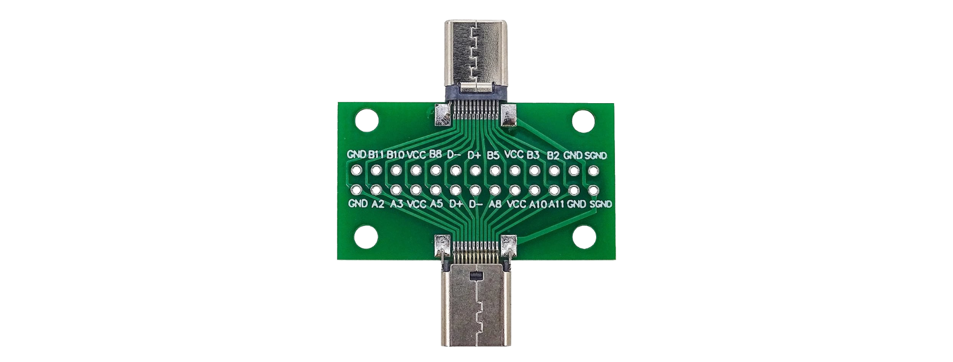
    • USB C intermediate connector
    • LM393P dual comparator
    • 3.3kΩ resistors (2pcs)
    • 1kΩ resistor
    • Wires

    Additionally, a device is needed to program the Bluepill. This tutorial assumes you have an ST-Link programmer (or compatible)

    USB C intermediate connector
    USB C intermediate connector

    Wiring

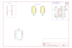
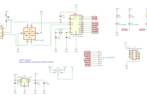
    • On the breadboard, create this schematic (left part only)
    • Connect it to the Bluepill board according to the STM32 F1 Family Pin Assignment (Monitor pins only)
    • Connect the USB C intermediate connector to the breadboard (GND, CC1 and CC2). Note that CC1 and CC2 might be called A5 and B5.

    Software

    In the Arduino IDE:

    • Install the library "USBPowerDelivery".
    • Create a new sketch based on the example "USBPowerDelivery > Protocol Analyzer"
    • Compile and upload it to the Bluepill

    For more detailed instructions, see https://github.com/manuelbl/usb-pd-arduino/wiki/USB-PD-Protocol-Analyzer-for-5-USD

View all instructions

Enjoy this project?

Share

Discussions

Similar Projects

Does this project spark your interest?

Become a member to follow this project and never miss any updates