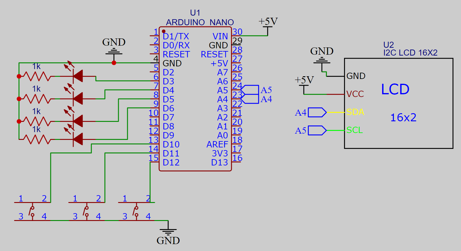
Arduino has 13 digital I/O pins and in this D10, D11 and D12 is reserved for action buttons. Others can be classified as output. Here I am using I2C module with 16x2 LCD which is a very great choice it reduce the number of connections. Using this we can display anything on screen via 2 wire interface connected on A4(SDA) and A5(SCL). Up, down and select buttons are internally pulled up and only a single 5v battery is needed as a power source. I want to make a vending machine for chips and chocolates.
But for this I have to combine a lot of electronics and mechanical parts together and one of them is LCD interface. That’s why I am learning how to make a simple LCD user interface to select a variety of things from menu. Here for now I am using 3 button LCD interface controlled by Arduino UNO/NANO to control four LED lights. The circuit is very simple and a very few components are required for it. It is my first LCD menu project and in future I will come with more version of the same project.
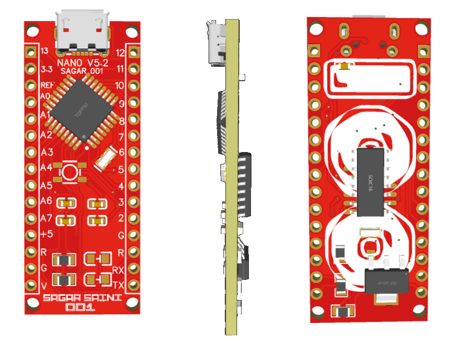
Either we can use a better screen like OLED and TFT or a better selecting knob instead of tactile buttons. A rotatory encoder is the best option of it. I am using my own made Arduino Nano which is designed by me and PCB fabricated from Custom PCB service.
Components required:
I2C 16x2 LCD screen
Arduino NANO/UNO
Tactile switches
Battery
Connecting wires, Breadboard or PCB
Circuit diagram:
Arduino has 13 digital I/O pins and in this D10, D11 and D12 is reserved for action buttons. Others can be classified as output. Here I am using I2C module with 16x2 LCD which is a very great choice it reduce the number of connections. Using this we can display anything on screen via 2 wire interface connected on A4(SDA) and A5(SCL). Up, down and select buttons are internally pulled up and only a single 5v battery is needed as a power source.
Output LEDs can be connected as per mentioned digital pins in the code. And for now these four LEDs are connected on Digital pin D3, D4, D5 and D6.
Arduino Code Explained:
1) First I initialize the code by defining the libraries, wire for I2C and Liquidcrystal for LCD. These libraries can be installed from manage library section under tools menu.
#include<Wire.h>#include<LiquidCrystal_I2C.h>
2) The all the input, output pins and counter is defined with initial positions.
LiquidCrystal_I2C lcd(0x27, 16, 2);
int upButton = 10;
int downButton = 11;
intselectButton = 12;
int menu = 1;
int LedOut1 = 3;
int LedOut2 = 4;
int LedOut3 = 5;
int LedOut4 = 6;
int Timer = 0;
int Timer_1 = 0;
int Timer2 = 0;
int Timer3 = 0;
3) Next step is to define the pin as input/ output and LCD startup routines.
4) To start with the main code I defined a counter menu with function updateMenu() in loop area. In this function the menu kept increasing and switch with case program is used.
6) In the action we can write different info or piece of code to execute different steps. here with the help of Timer, Timer_1, Timer2 and Timer3 counters I made a Led toggling unit.
/*
* MADE BY Lithium Ion
*/#include<Wire.h>#include<LiquidCrystal_I2C.h>LiquidCrystal_I2C lcd(0x27, 16, 2);
int upButton = 10;
int downButton = 11;
int selectButton = 12;
int menu = 1;
int LedOut1 = 3;
int LedOut2 = 4;
int LedOut3 = 5;
int LedOut4 = 6;
int Timer = 0;
int Timer_1 = 0;
int Timer2 = 0;
int Timer3 = 0;
voidsetup(){
lcd.init();
  lcd.backlight();
  pinMode(upButton, INPUT_PULLUP);
  pinMode(downButton, INPUT_PULLUP);
  pinMode(selectButton, INPUT_PULLUP);
  pinMode(LedOut1, OUTPUT);
  pinMode(LedOut2, OUTPUT);
  pinMode(LedOut3, OUTPUT);
  pinMode(LedOut4, OUTPUT);
updateMenu();
}
voidloop(){
if (!digitalRead(downButton)){
menu++;
updateMenu();
delay(100);
while (!digitalRead(downButton));
}
if (!digitalRead(upButton)){
menu--;
updateMenu();
delay(100);
while(!digitalRead(upButton));
}
if (!digitalRead(selectButton)){
executeAction();
updateMenu();
delay(100);
while (!digitalRead(selectButton));
}
}
voidupdateMenu(){
switch (menu) {
case0:
menu = 1;
break;
case1:
lcd.clear();
lcd.print(">LED1");
lcd.setCursor(0, 1);
lcd.print(" LED2");
break;
case2:
lcd.clear();
lcd.print(" LED1");
lcd.setCursor(0, 1);
lcd.print(">LED2");
break;
case3:
lcd.clear();
lcd.print(">LED3");
lcd.setCursor(0, 1);
lcd.print(" LED4");
break;
case4:
lcd.clear();
lcd.print(" LED3");
lcd.setCursor(0, 1);
lcd.print(">LED4");
break;
case5:
menu = 4;
break;
}
}
voidexecuteAction(){
switch (menu) {
case1:
action1();
break;
case2:
action2();
break;
case3:
action3();
break;
case4:
action4();
break;
}
}
voidaction1(){
lcd.clear();
lcd.print(">Toggle Led #1");
digitalWrite(LedOut1,HIGH);
Timer++;
if(Timer ==2){
digitalWrite(LedOut1,LOW);
Timer=0;
}
else{
digitalWrite(LedOut1,HIGH);
}
delay(1500);
}
voidaction2(){
lcd.clear();
lcd.print(">Toggle Led #2");
digitalWrite(LedOut2, HIGH);
Timer_1++;
if(Timer_1 ==2){
digitalWrite(LedOut2,LOW);
Timer_1=0;
}
else{
digitalWrite(LedOut2,HIGH);
}
delay(1500);
}
voidaction3(){
lcd.clear();
lcd.print(">Toggle Led #3");
digitalWrite(LedOut3, HIGH);
Timer2++;
if(Timer2 ==2){
digitalWrite(LedOut3,LOW);
Timer2=0;
}
else{
digitalWrite(LedOut3,HIGH);
}
delay(1500);
}
voidaction4(){
lcd.clear();
lcd.print(">Toggle Led #4");
digitalWrite(LedOut4,HIGH);
Timer3++;
if(Timer3 ==2){
digitalWrite(LedOut4,LOW);
Timer3=0;
}
else{
digitalWrite(LedOut4,HIGH);
}
delay(1500);
}
Working and Testing:
I initializes 4 timer for 4 modes which may increase the programming space, so in the next modifying sketch I will try to use flags option of Arduino and combine that with one tactile button or a rotatory encoder.
You can increase the number of Menu or inside action secondary menu. Here I demonstrate only with the help of counter how to toggle the LEDs alternatively. The code and circuit diagram is working properly and it is recommended to add a 10uf capacitor between power lines to reduce noise due to wires.
Own Arduino Nano:
I made my own Arduino Nano microcontroller board using PCBWAY prototype service. The ordering process is quite easy just fill the parameters of board choose color, thickness and type of finishing and then add it into cart.
Upload your Gerber files and you will get the quote within 1 hour, You can discuss the specifications with the engineering team. For these PCB layouts I choose red color, HASL finishing and I got 5pcs these amazing quality boards just in $5. Visit PCBWAY from here and see full article on Arduino making from here.
 Lithium ION