 ElectroBoy
In this tutorial, we are designing an AC amplifier using operational amplifier. The basic amplifying action of the operational amplifiers remains same as stated in dc amplifier section also. But that type of amplifier is only to amplify the small dc values. In AC amplifiers Q point(operating point value) is very important. Q point is basically a DC value (on DC load line) over which the ac signal is superimposed for the faithful amplification. This value Q point is generally a mid-value to get the maximum signal efficiency.
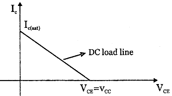
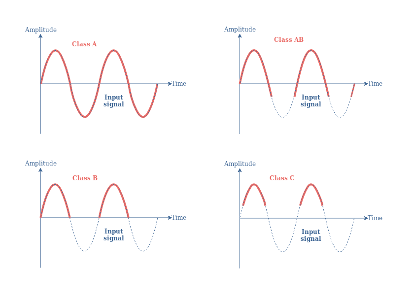
Here we can set the Q-point in case of audio amplifier to adjust the signal to power efficiency ratio. These points are categorised as classes (A, B, AB, C). In below given graph you can see the all. But here the operational amplifier is used to amplify small signal superimposed on a DC signal. That’s why here we are setting the operating point in middle so there will be no loss of signal, the maximum faithful amplification is possible.
You can access both previous tutorials from here:
1) Getting started with operational amplifiers
2) DC Operational amplifier using OP-AMP
Components required:
Components required:
- LM358 operational amplifier
- Resistors (1K and 10K)
- Potentiometer (100K)
- Custom PCB from JLCPCB
- Power supply (5V)

Because I want to design this operational amplifier for different purposes so I am going for variable jumpers that will set the overall gain ratio, and I am using PCB prototype service from JLCPCB.
Setting the configuration of op-amp:

First, we have to choose the configuration either you can choose non-inverting or inverting the basics remain the same. Because we are designing it for a gain circuit, so closed loop configuration is used. I choose inverting configuration in which signal is given on inverting pin and the Q point is set through the virtual ground concept from non-inverting terminal. To set the gain resistors Rf and Rin can be adjusted. And the gain is given by the formula: -Rf/Rin (minus sign shows the phase shift of 180).
Setting the operating point:
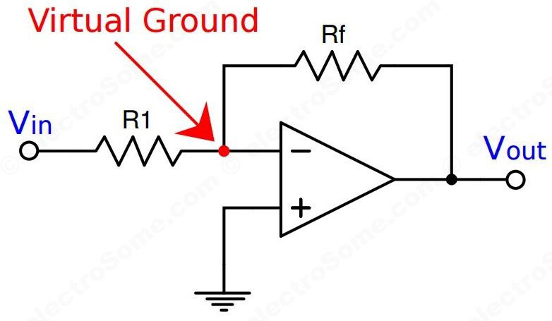
To set the operating point the concept of virtual ground is used, because the input terminal of operational amplifiers don’t need any current so the only path is the feedback loop. And the operational amplifier tries to maintain the same voltage on both inputs. By choosing two same resistors a voltage divider is established between ground and VCC and the output voltage is just the middle of these. Which can be used to set the operating point of the operational amplifier in the middle.
Circuit diagram:

We are operating this operational amplifier on 5volt supply, so a middle voltage of 2.5volt is set by the voltage divider configuration (using same values resistors). Two small coupling capacitors are needed for the input and output to ensure that input and output to the system is only AC (a varying signal). Then set the gain resistors and negative feedback to the operational amplifiers. I made this AC amplifier for the adjustable gain, so by selecting the gain value ratio through onboard jumpers you can use this amplifier system directly.
PCB and Gerber designs:
I made the schematics and Gerber files in EASYEDA and exported them, these GERBER files can be directly used to order the PCB from Custom PCB service. Select the jumpers to adjust the gain settings. I am using 3 different gain settings which provides a gain listed on gain set jumper.

Working and testing:

The output of amplifier is quite stable and proper, you can make this amplifier using the same schematics. The input to the system should be within the limit of power supply added to it, otherwise there will be saturation. To avoid sudden saturation minimize the gain before applying input signal to the amplifier system. In future, I will also cover some more topics on operational amplifier (main applications). The high amplitude signal on the input cause upper- and lower-part signal saturation...
Read more »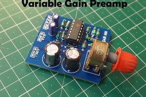
 Sagar 001
 mircemk
 Manuel Tosone
 Ghani Lawal