PUTMotorsport
Transmitted data:
- Accelerator pedal position o Brake systems pressures
- Speeds of all 4 wheels o GPS position
- Power, that the inverter sends to the motor
- State of charge of the low voltage battery.
- State of charge of the high voltage battery.
- Inverter temperature
- Motor temperature
- Low voltage battery temperature
- High voltage battery temperature
- Water temperature
- State of the car
- Tire temperatures
Whole project can be found here: https://github.com/PUT-Motorsport
Block Diagram of the System:


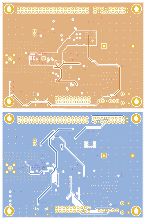
Final Layout
4 layer PCB was used, cause of lower distances between copper layers, and simultaneously not significantly higher cost. The ground plane was poured on every layer. The 3.3V power was routed on layer 2. JLC PCB JLC04161H-7628 stackup was used.
Final layout was designed to fit on the top of already in-use motherboard: https://www.instructables.com/Multi-PCB-Motherboard/

 Pariv
Pariv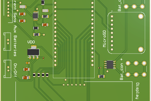
 psemportugal
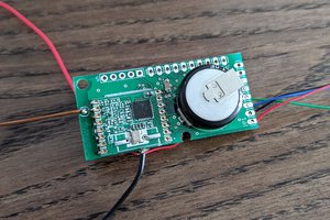
 strange.rand