Close
0%
0%

AMP Robot - Assistive Mobile Power Robot

A small robot that automatically plugs in and charges a mobility scooter or wheelchair.

Similar projects worth following
AMP Robot is designed to empower individuals with motor disabilities by providing an autonomous power connection for their mobility scooters or wheelchairs.

By addressing the challenges posed by limited fine motor skills, AMP Robot enables users to maintain independence and freedom in their daily lives. Built around a Raspberry Pi 3 and leveraging computer vision capabilities, this robot autonomously navigates towards the scooter or wheelchair and establishes a secure power link.

Inspired by the difficulties faced by individuals with motor disabilities, particularly my father's experience with MS, this project aims to further enable that mobility remains within the user's control. By removing the task of power connections from caregivers, AMP Robot allows individuals to retain their independence and eliminates the risk of being housebound due to an uncharged scooter or wheelchair.

Technical Details

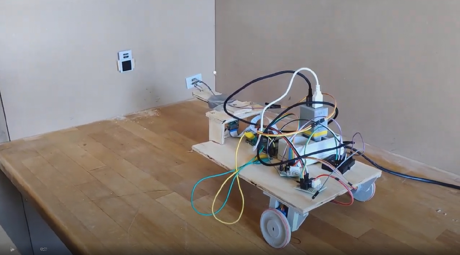
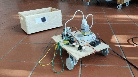
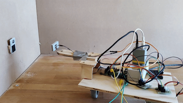
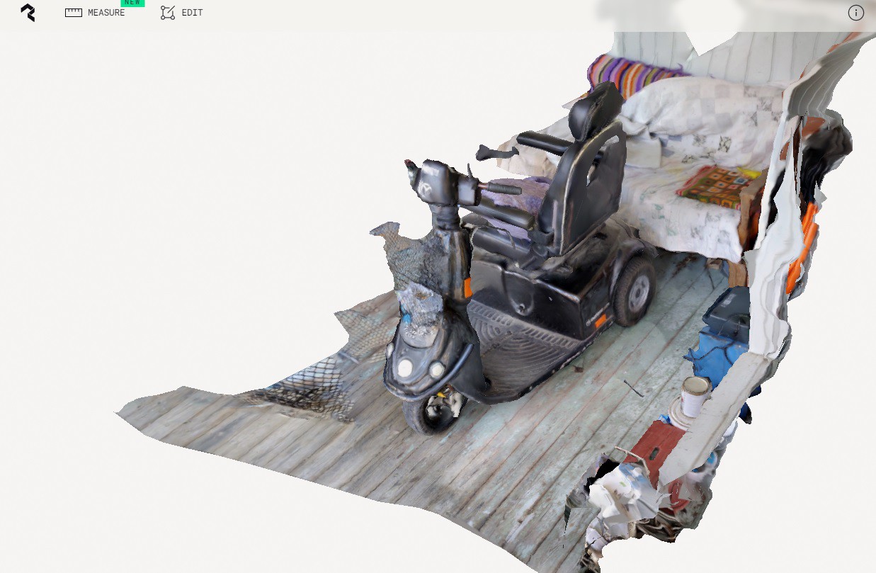
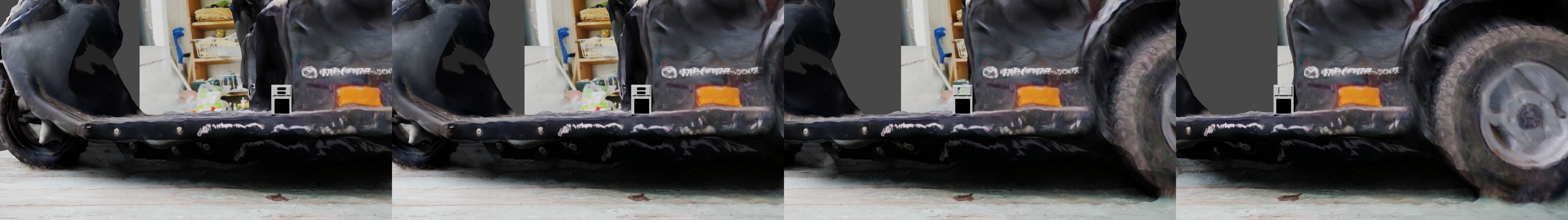
AMP Robot is built around a Raspberry Pi 3, incorporating a Raspberry Pi camera module, 28BYJ-48 stepper motors with ULN2003AN Stepper Motor Modules, and custom 3D-printed parts. Using Python and OpenCV, the robot employs computer vision techniques for autonomous navigation towards the mobility scooter. A custom-designed connector, coupled with magnetic pogo stick connectors, establishes a secure power link between AMP Robot and the scooter's XLR male and female ports.

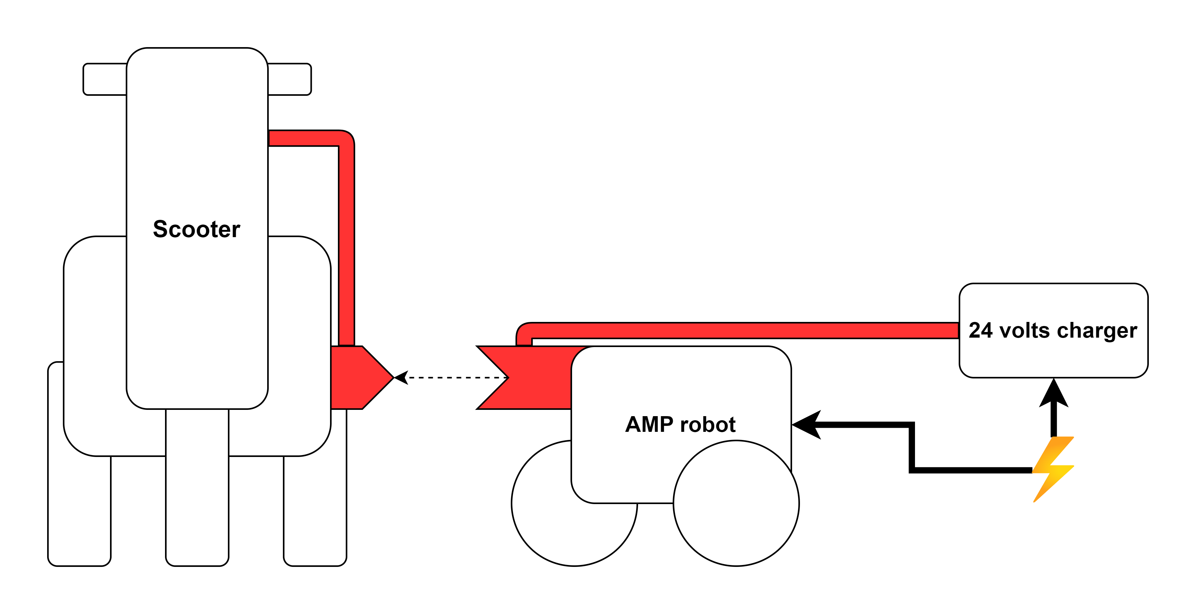
Autonomy: AMP Robot autonomously identifies and navigates towards the mobility scooter, minimizing the need for manual intervention.
  1. Reliable Power Connection: The custom-designed connector and magnetic pogo stick connectors ensure a robust and secure power link.
  2. User-Friendly Operation: AMP Robot requires no or minimal user input for initiating the power connection process.
  3. Expandability: The modular design allows for future enhancements and customization to accommodate different scooter models.

BOM:

Raspberry Pi 3: $70 (est.) Raspberry Pi Camera Module: $30 28BYJ-48 Stepper Motors (2): $8 ULN2003AN Stepper Motor Modules (2): $4 Magnetic Pogo Stick Connectors: $10 XLR Connectors: $5

total: $130 (est.)

  • 2: First physical prototype

    Niklas Frost05/25/2023 at 07:40 0 comments

    Moving from virtual exploration to physical implementation, I embarked on creating a tangible prototype for my project. The primary components of this prototype included two 28BYJ-48 stepper motors, connected to the left and right back wheels, along with a front swivel wheel. These mechanisms were mounted on a sturdy piece of plywood, forming the base of the robot.

    To control the robot's movements, I employed a Raspberry Pi 3 equipped with a camera. This setup allowed for real-time control and feedback during operation. Additionally, I attached the 3D printed version of the connector, which I had previously designed, to a wall. The robot was positioned in front of the connector, ready for testing and interaction.

    In order to assess the robot's ability to navigate towards the connector, I devised a systematic approach. First, I implemented a loop that instructed the robot to move forward by 2000 steps of the motor wheels. Simultaneously, the OpenCV code captured the size of the indicator within each iteration. This data was crucial for subsequent analysis.

    Utilizing the collected information, I constructed a graph that allowed me to estimate the distance between the camera and the indicator in terms of motor steps. This quantitative estimation formed the basis for developing a mechanism that would autonomously guide the robot towards the indicator. By incorporating this feedback loop, the robot could continuously adapt its movements to reach the desired target.


    To ensure accuracy and precision, I also incorporated a mechanism for aligning the robot with the indicator. By dynamically adjusting its orientation, the robot could position the indicator at the center of its field of view. This alignment step further improved the reliability and efficiency of the navigation process.

    Combining these elements together, I achieved a significant milestone in my project. Through a successful trial, I witnessed the robot autonomously moving from an off-center position towards the connector. Additionally, I designed and implemented an alternative connector specifically for the robot, allowing it to establish a successful connection upon reaching the target.

    The successful outcome of this initial prototype is a testament to the viability of my project's concept. It lays a strong foundation for further enhancements and refinements as I continue to explore and advance the capabilities of my autonomous robot.

  • 1: Virtual prototyping

    Niklas Frost05/24/2023 at 22:31 0 comments

    To ensure the feasibility of my project before diving into physical prototyping, I decided to explore a virtual approach. My goal was to assess whether the system could be operational without the need for an actual prototype.

    To begin, I employed PolyCam to conduct a 3D scan of the mobility scooter and its surroundings. This provided me with a digital representation of the scooter, which served as the foundation for subsequent virtual experiments.

    Utilizing Blender, I integrated a 3D model of a connector into the scene of the 3D scanned scooter. The connector comprised two elements: the magnetic power connector on top and a black square at the bottom, acting as an indicator. This virtual setup allowed me to simulate the interactions between the robot and the connector.

    To evaluate the robot's ability to locate the connector, I generated image sequences from the perspective of a potential robot. This provided me with different viewpoints to assess the system's performance. Additionally, I utilized various light settings within Blender to emulate different lighting conditions, ensuring comprehensive testing.

    Next, I employed OpenCV in conjunction with Python to establish a blob detector. This detector consistently identified the square indicator within the rendered images. Once the square was detected, it served as a reference point for the robot's alignment with the connector. By analyzing the position of the indicator-square relative to the center of the image, the robot could determine its alignment. Furthermore, the size of the square offered insight into the robot's proximity to the connector.

    The successful virtual prototyping of the robot's navigation components instilled confidence in the feasibility of utilizing a camera and OpenCV for its navigation.

    By leveraging virtual simulations and advanced image processing techniques, I have gained valuable insights into the potential success of my project. These preliminary experiments provide a solid foundation for further development and bring me closer to achieving my ultimate goal.

View all 2 project logs

Enjoy this project?

Share

Discussions

Similar Projects

Does this project spark your interest?

Become a member to follow this project and never miss any updates