Vijay
Vijay-
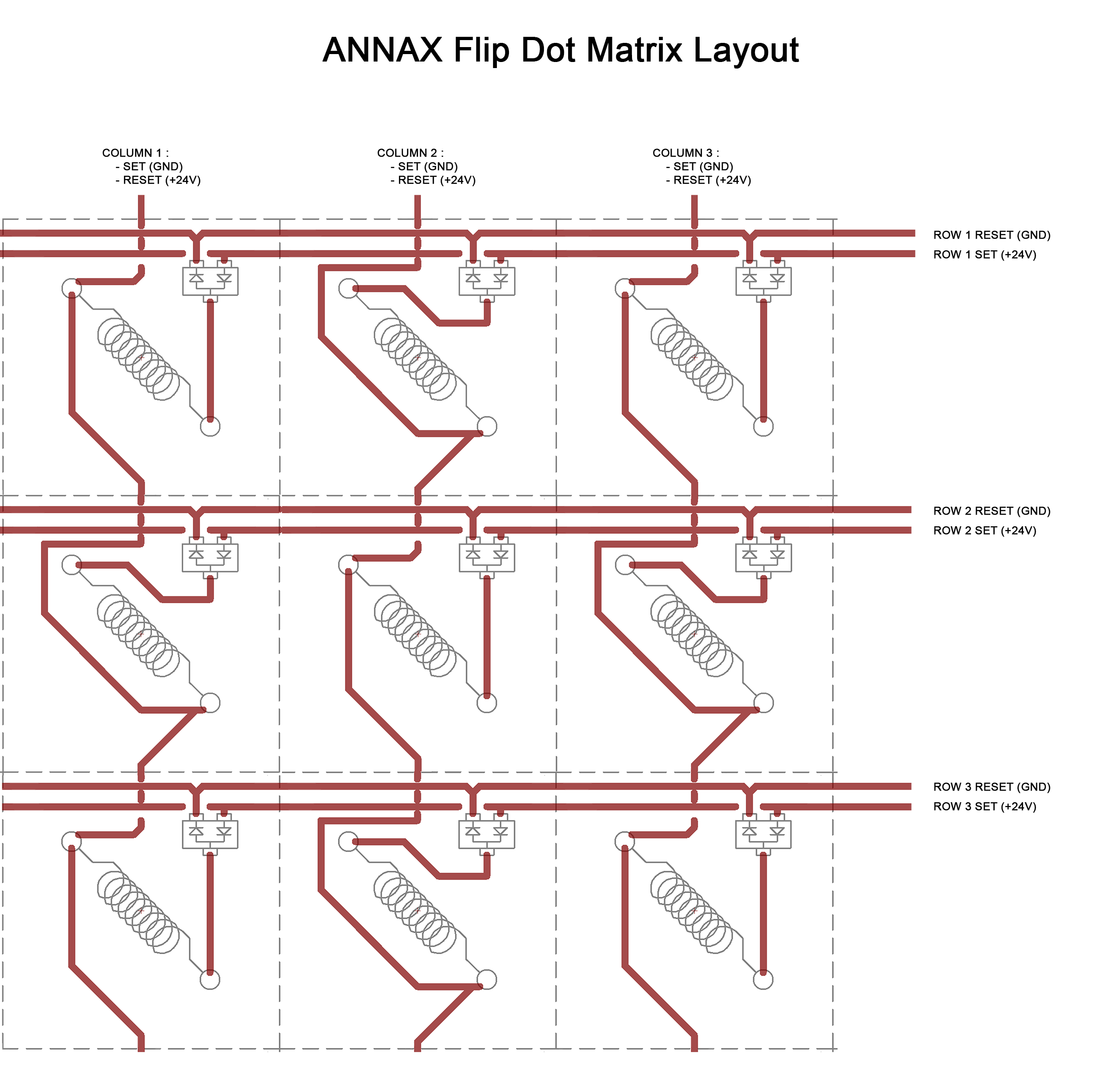
Updated Drive Electronics
09/13/2023 at 03:34 • 0 commentsI spent a few days on Proteus simulating the circuit and was dismayed that is didnt work
Then I found amazing documentation by Frederic L on his Flip Dot Display Controller project ( https://hackaday.io/project/159415-flip-dot-display-diy-controller ), and was pleasently surprised that we had a similar approach using Source and Sink Trasistor Arrays, but used Shift-Registers instead of Decoders.
Trying to figure out why my circuit wouldnt work [ Seems that I cant connect the outputs of the Source and Sink trasistor arrays together directly if I want the circuit to work on Proteus atleast], I found on one of his log that the Flip-Dot pannel has some additional components, namely Swiching diodes placed between the Source and Sink on each coil:![]()
When added these into the circuit, things still wouldnt work, as then proceeded to add one switching resistor pair to the common conenction of the coils for each module, and voila!
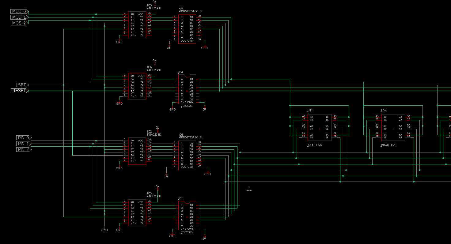
The Above Video shows the working simulation. I used UDN2981's for the source drivers and ULN2803's for the SINK, analogous to the ones I chose before in the last log. All the pins of a single module are arranged in a vertical line and show only 2 modules for simplicity.
As a suggestion by kelvinA on the previous log, I've used the Active Low enable pins of the Decoder IC and connected them to SET/RESET in a way to prevent shoot-through condition of the H bridge.
The next step is designing the board with this schematic! -
Braille Cell Array Drive Circuit
09/10/2023 at 17:44 • 2 comments![]()
I'm working on the drive electronics to actuate pins for an array of braille cells that can make up a full braille display.
I have been looking into the functioning of Flip-Dots, as they share many similar characteristics to each Braille-Cell dot.
![Flipping Dots Fast. | About using electronic stuff]()
Above: A single Flip dot toggles its position when the polarity of an electromagnet is changed.
![]()
Above: A single Braille dot toggles its position when the polarity of an electromagnet is changed.
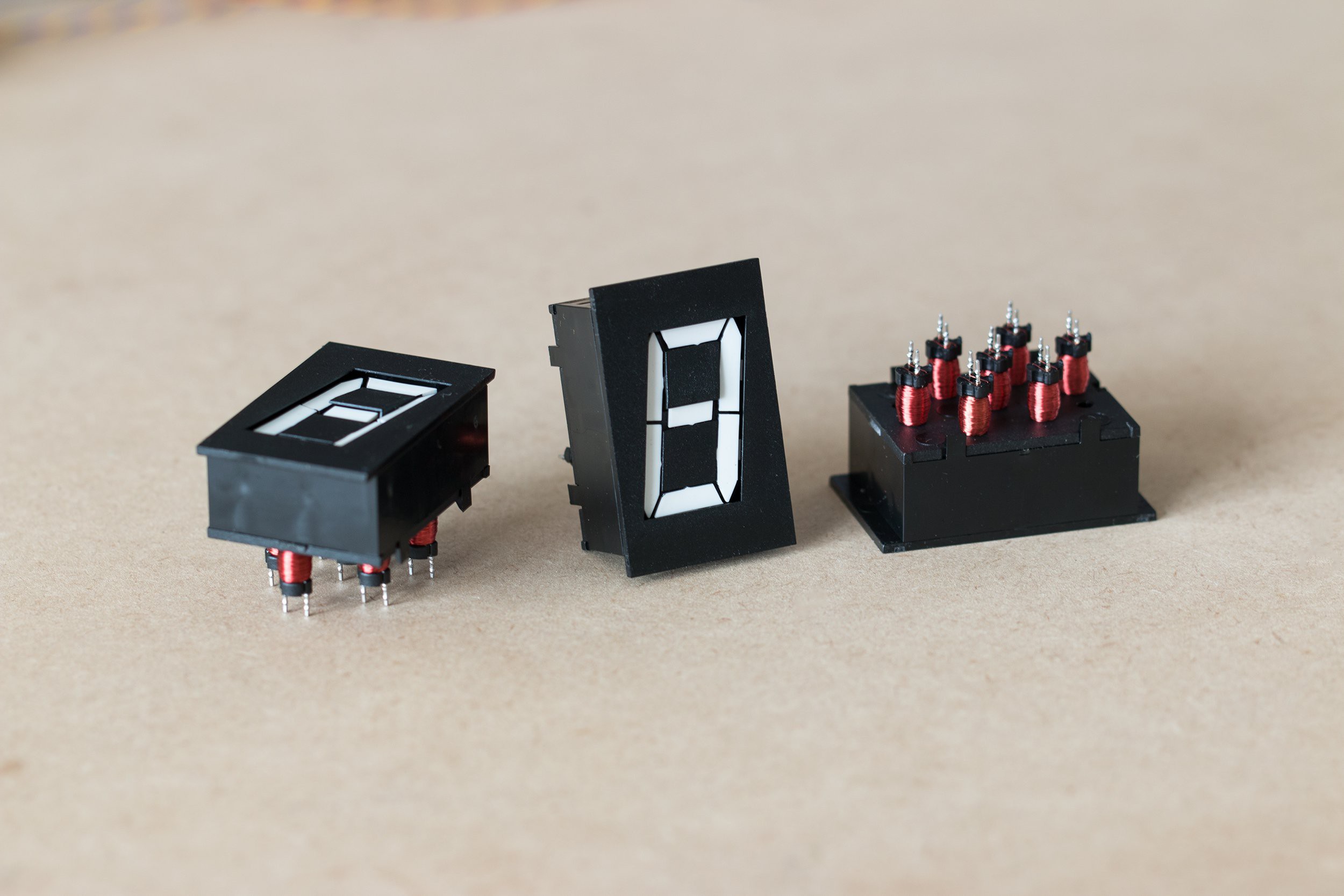
Luckily, there are several projects on Hackaday to learn from (Hackaday community seems to love these). I found these amazing mechanical 7-Segment displays from AlfaZeta that are a perfect analogy for the Braille-Cell, each segment works just like an individual flip dot, and 7 segments of them are packaged into a module where each segment need to be energised only momentarily and then retains its state, similar to our 6-dot Braille Cell:
![]()
![]()
I found a project that just "Throws H-Bridges" at the module to drive them, but I wanted to be able to save on money and microcontroller pins to create a more elegant solution, and keep the cost lower than the 10$ per Braille-Cell goal I have for the project:
https://hackaday.io/project/162065-wifi-flip-clockyoutube-counter
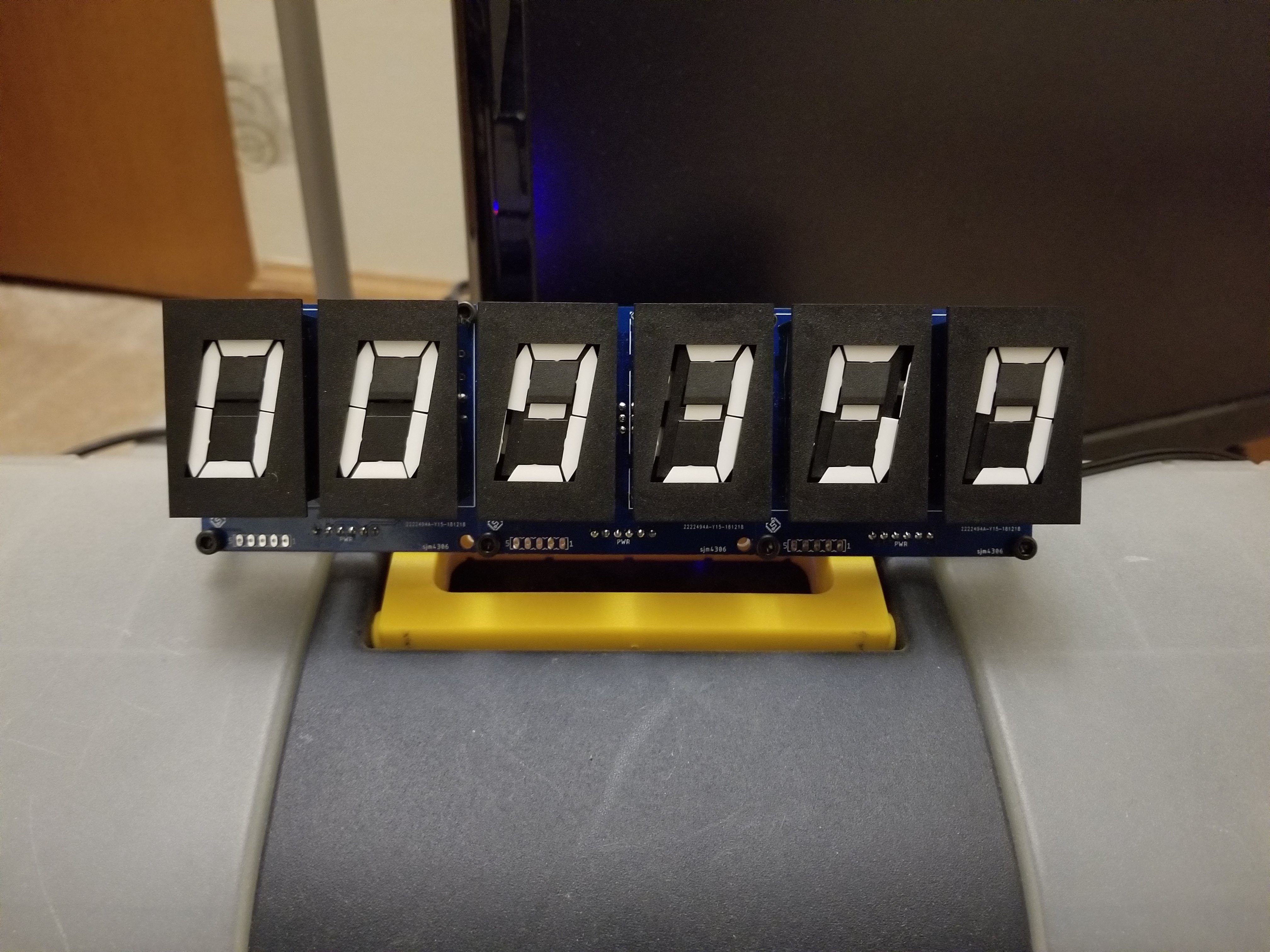
I came across this video by YouTuber GratScott! that showed an array of these modules controlled by some interesting electronics:
The circuit on this is what Ive decided to reverse engineer as best as possible for a using 6-dot braille cells.
![]()
How the driver works (I think), taking the example of driving 5 Braille Cell Modules:
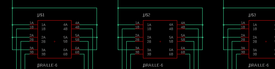
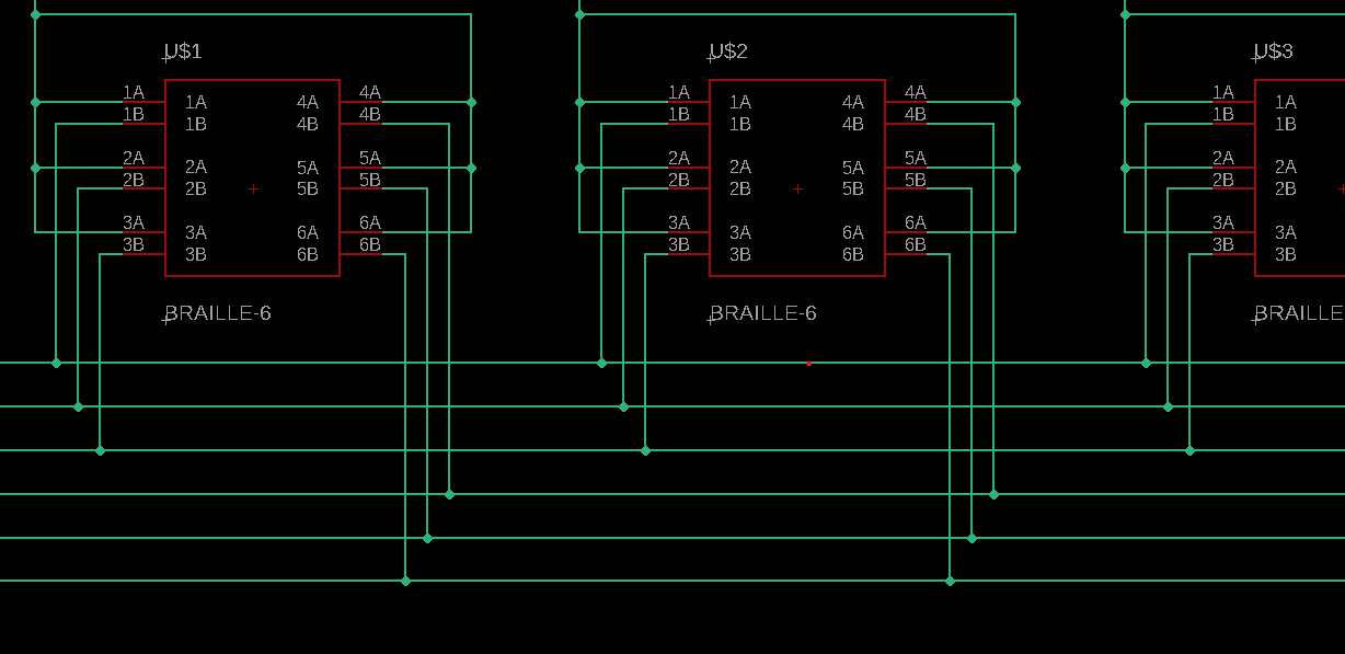
- On each 6-Segment Braille Cell, one end of the solenoid of each segment is connected together in common. Pictured below is the schematic, 1A and 1B are a single coil, 2A and 2B another, and so on. The A's of all coils of a single module are connected together.
![]()
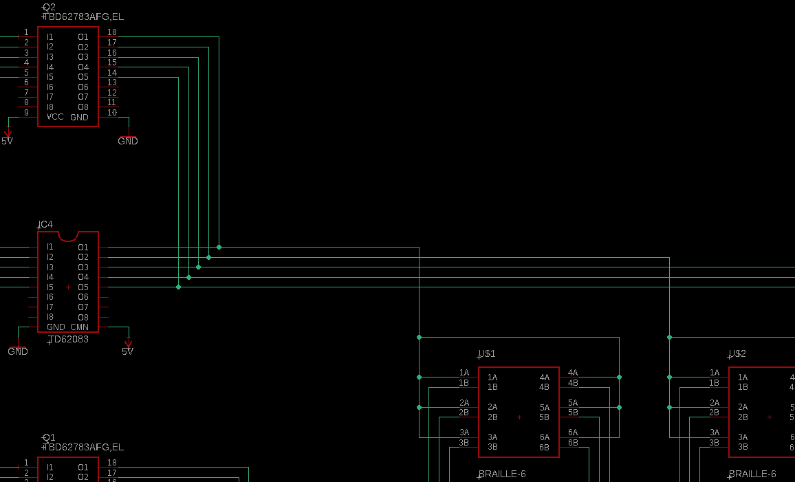
- Each common connection of every Braille Cell is connected to a channel of a source type DMOS transistor array(TBD62783APG https://toshiba.semicon-storage.com/info/TBD62783APG_datasheet_en_20160511.pdf?did=30523&prodName=TBD62783APG) as well as a Sink type transistor array (TBD62083APG https://toshiba.semicon-storage.com/info/TBD62083AFG_datasheet_en_20160511.pdf?did=29893&prodName=TBD62083AFG , Similar to a ULN2003) creating a Half H Bridge circuit
![]()
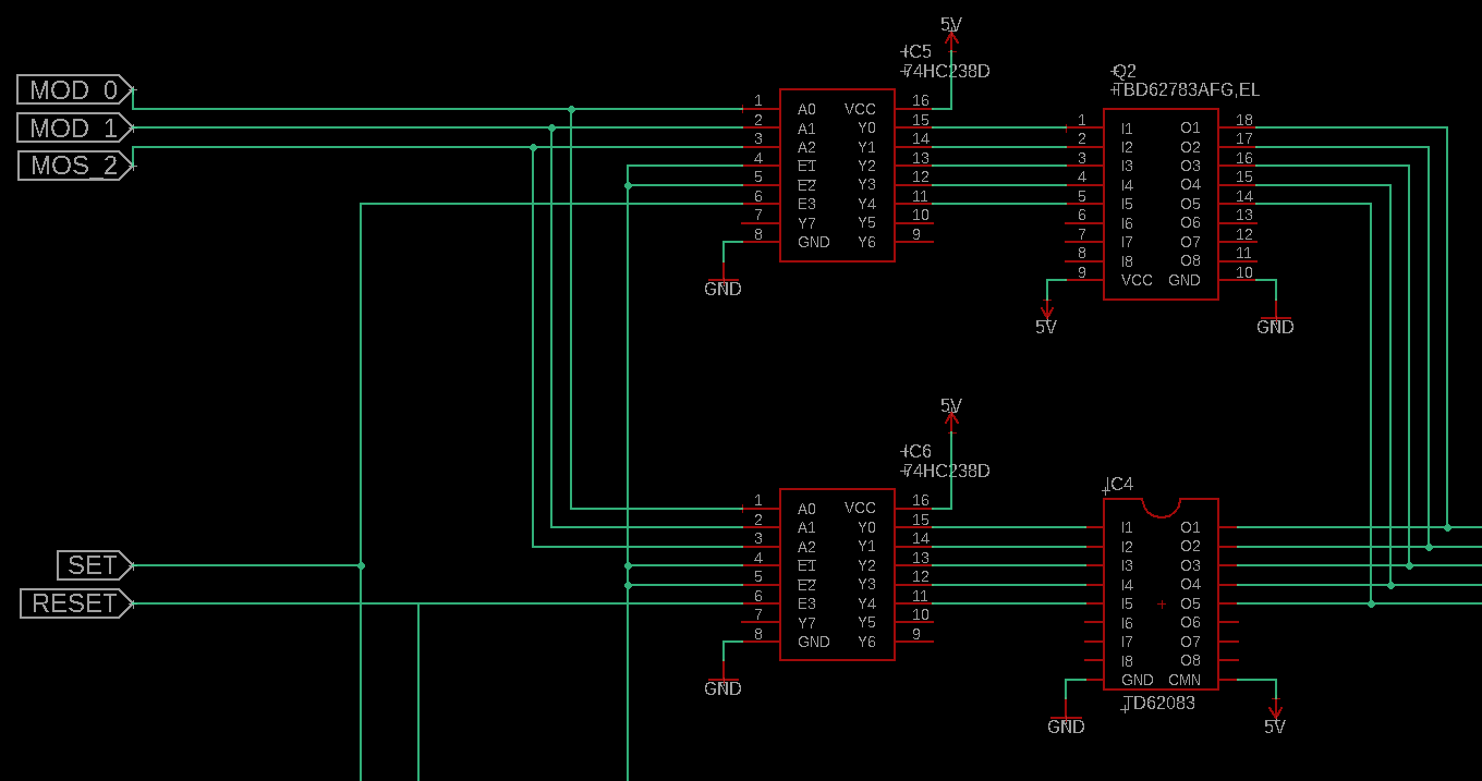
- The inputs of both the source and sink transistor arrays are connected to two CMOS 3-to-8 Decoder ICs( (74HC2238D https://toshiba.semicon-storage.com/info/74HC238D_datasheet_en_20160804.pdf?did=37298&prodName=74HC238D ) . The inputs of both these decoder ICs are connected together to MOD_0, MOD_1, and MOD_2 which will go to the MCU pins. These will be responsible for selecting which module to select for driving.
- SET & RESET are connected to the Enable PIns of the decoder connected to the Source Transistor Array and the SInk Transistor array respectively. These will be responsible for connecting the common connection of each Braille Cell Module to the source or sink by activating the decoder-transistor IC pairs. SET and RESET Cannot be both HIGH or else the half H bridge will be in a "shoot-through" state, releasing magic smoke.
![]()
In a similar manner, the other end of each coil of each braille cell is connected in parallel with the respective coils of other braille cell modules.
![]()
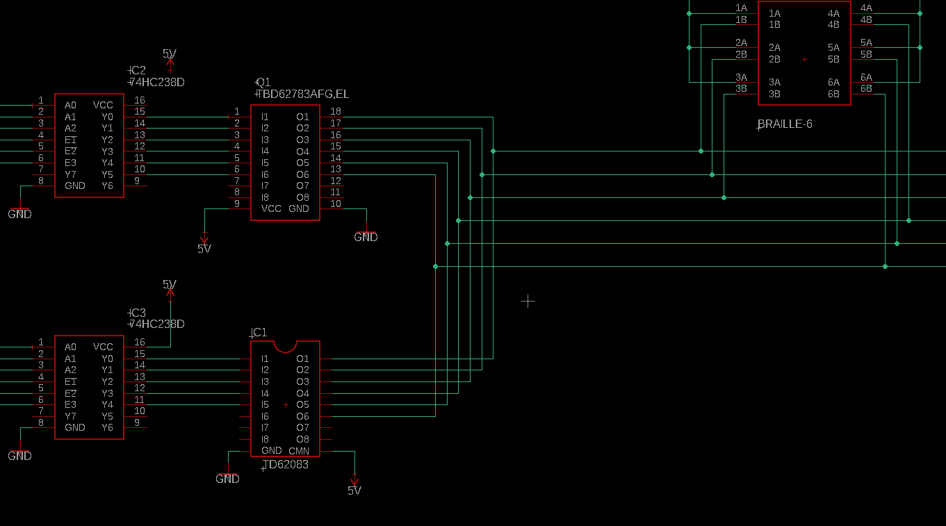
These are in turn connected in a similar arrangement as the common connections for each module, connected to a source and sink transistor array, controlled with 3 to 8 decoder ICs
![]()
- The inputs of both these decoder ICs are connected together to PIN_0, PIN_1, and PIN_2 which will go to the MCU pins. These will be responsible for selecting which PIn to drive to select for driving.
- SET & RESET are connected to the Enable PIns of the decoder connected to the Sink Transistor Array and the Source Transistor array respectively. If SET was enabling the Source Transistor Array on the Common connection of the module, on the Pin side, SET would be connected to enable the decoder IC that enables the Sink Transistor Array, thereby completing the H-Bridge connection, with half an H-Bridge connected to the Common PIn, and the other half connected to each individual pin.
![]()
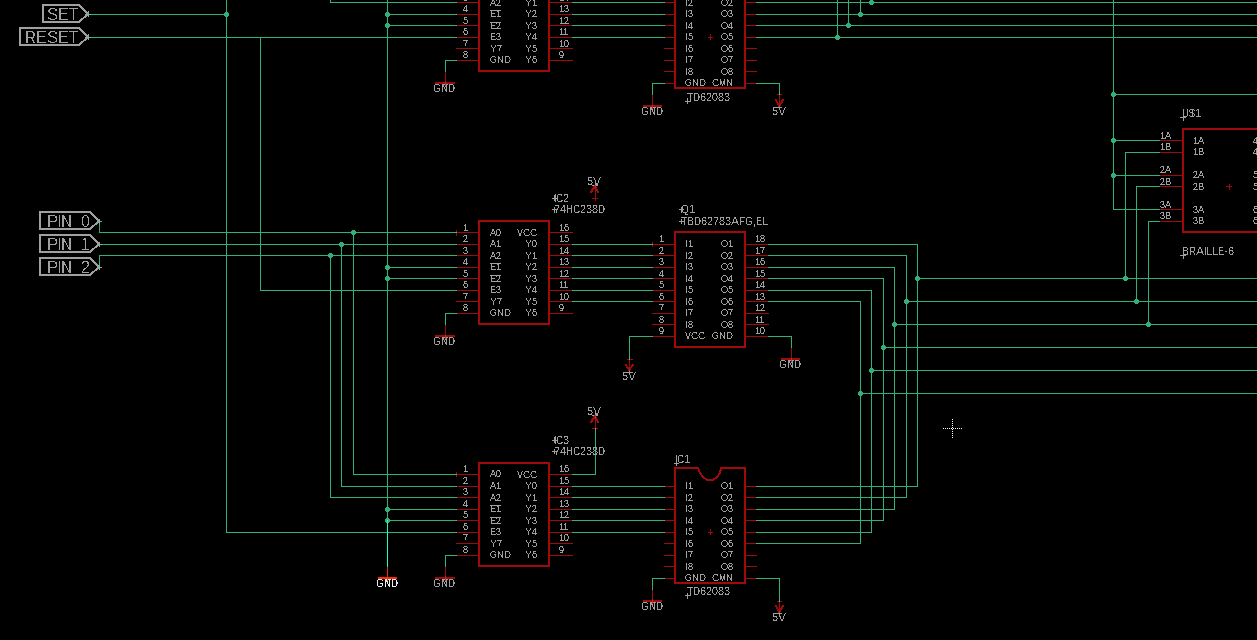
- Here is what the circuit looks like all together:
![]()
Download the Schematic above here: https://cdn.hackaday.io/files/1911818179487904/Braille%20V1.sch
Functioning:
- Consider all pins/modules to be in a RESET state to start, implying all dots are lowered, and the solenoids haven't been activated.
- MCU selects the Module whose pins to activate by settings MOD_1, MOD_2, and MOD_3.
- MCU Selects the Pin of the Module to activate by setting PIN_1, PIN_2, and PIN_3.
- The MCU will give a HIGH pulse ( long enough for the pins to be actuated/raised) on the SET pin, which activates the Source Transistor Array on the common side of the coil, and the Sink Transistor Array on the pin side, in turn driving the current in one direction in the selected pin.
- Other pins are sequentially activated by setting PIN_1, PIN_2, and PIN_3. and pulsing the SET pin.
- Before setting a module with a new pin arrangement, all the pins will need to be reset to the lower position
- MCU selects the Module whose pins to lowered by settings MOD_1, MOD_2 and MOD_3.
- MCU Selects the PIN of the Module to be lowered by setting PIN_1, PIN_2 and PIN_3.
- The MCU will give a HIGH pulse ( long enough for the pins to be Lowered ) on the RESET pin, which activates the Sink Transistor Array on the common side of the coil, and the Source Transistor Array on the pin side, in turn driving the current in the other direction in the selected pin than before.
- Other pins are sequentially lowered by setting PIN_1, PIN_2, and PIN_3. and pulsing the SET pin.
Questions/Doubts I have:
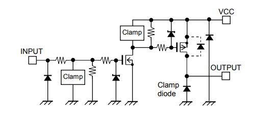
- Want to confirm that the input pins to the TBD62783APG & TBD62083APG are all active HIGH. I'm confused since usually on a source side Darlington, you need to give a LOW signal to actuate it. But that may not be the case as the equivalent circuit is different:
![]()
- Since I'm driving inductive loads Should I add flyback diodes in the circuit ( how and where? ) or rely on the Clamp diodes included in the transistor arrays
- Am I missing anything in the circuit? Is there anything I have not considered? Are components/connections missing to get this work?
- Is there a better way to do this driver circuit?
Download the Schematic above here: https://cdn.hackaday.io/files/1911818179487904/Braille%20V1.sch
-
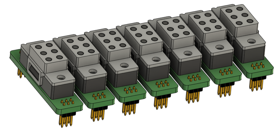
1st 3D Printed Prototypes
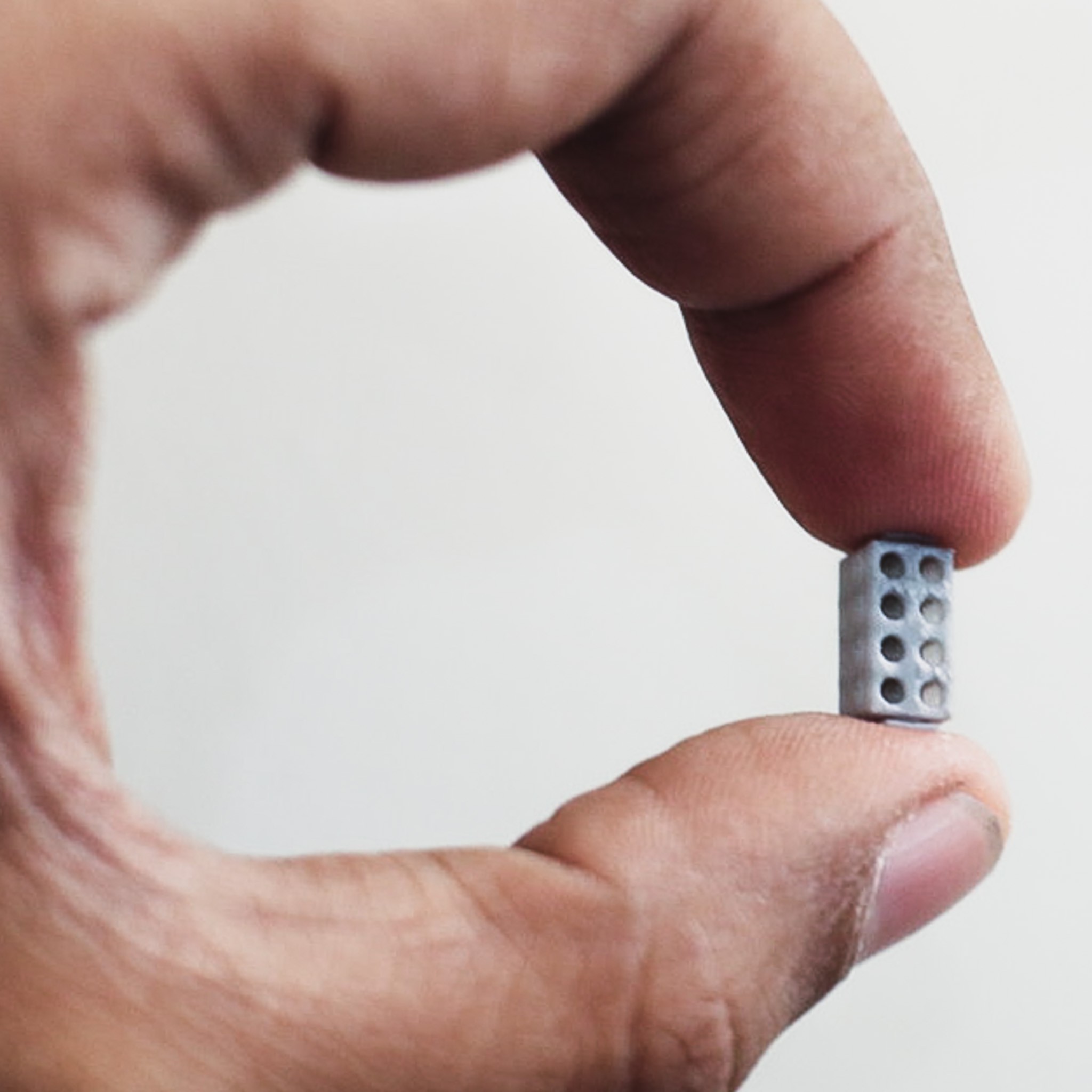
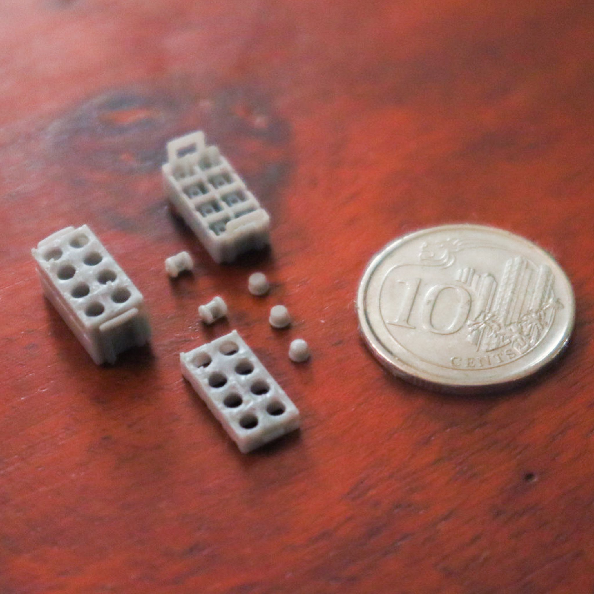
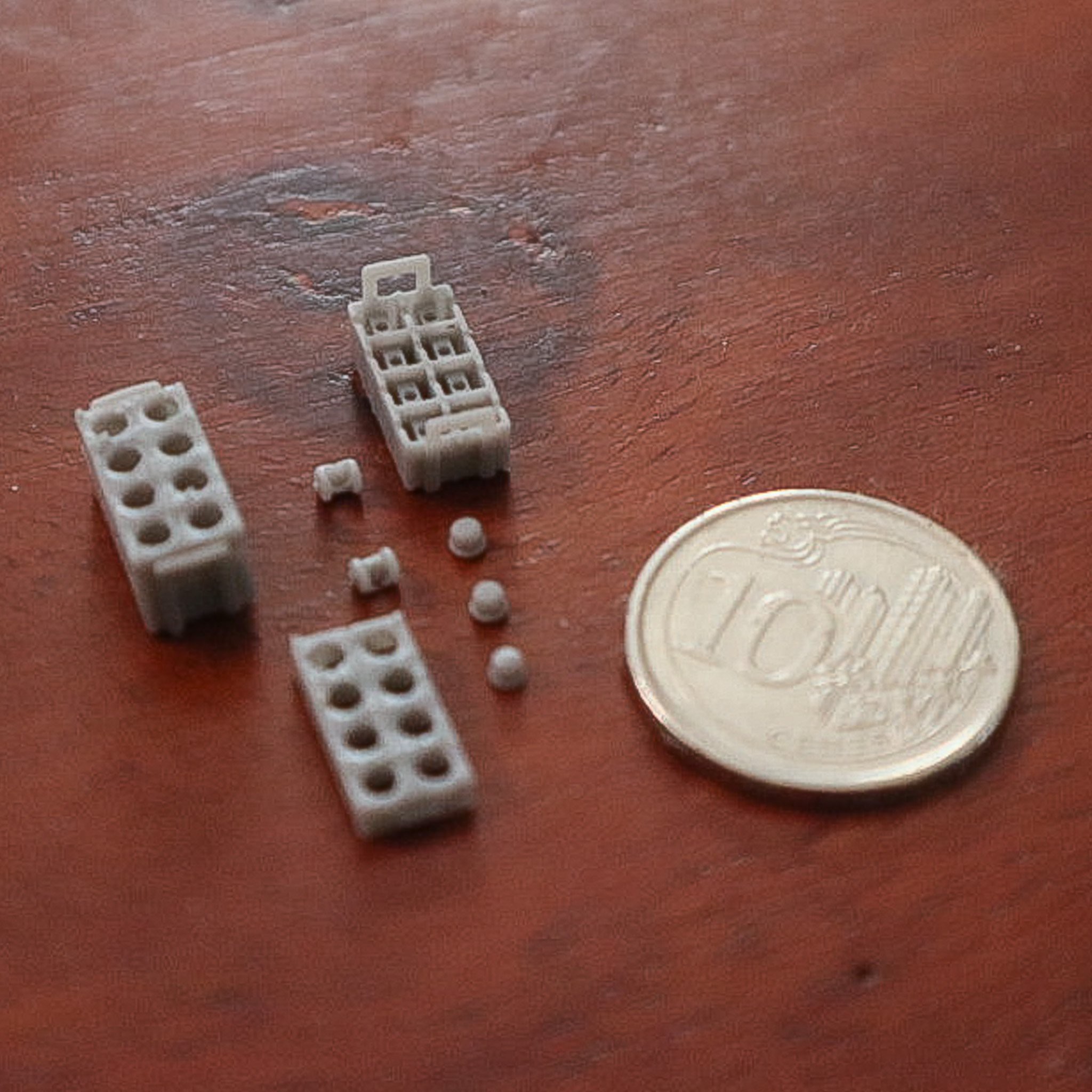
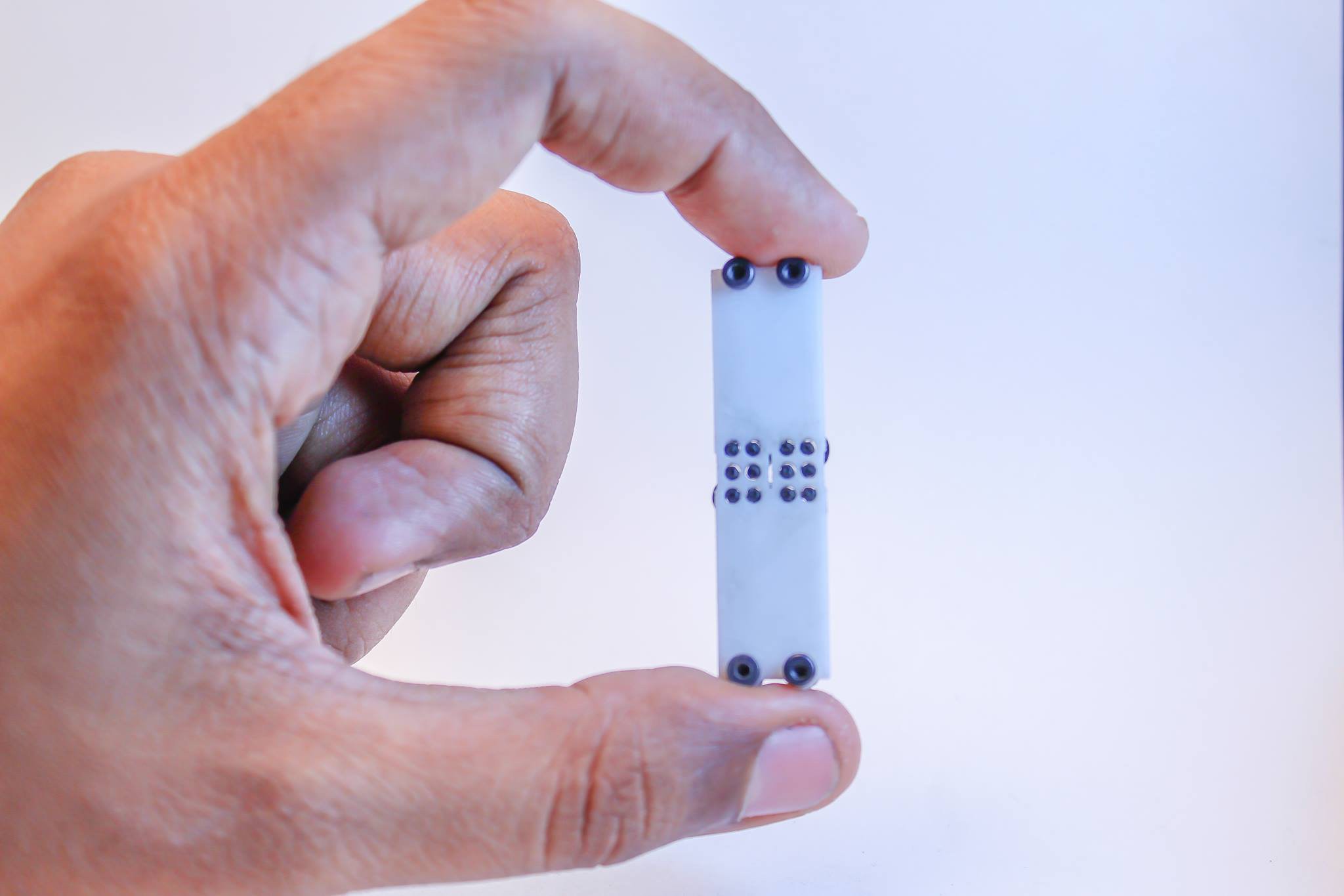
05/28/2023 at 07:28 • 0 comments![]()
Hey there, Hackaday community! I wanted to share an exciting update on my ongoing project focused on 3D printing small Braille parts. Today, I want to discuss the significance of resolution when it comes to creating high-quality Braille tactile components.
One of the most critical factors in creating functional Braille parts is achieving a high level of detail and precision. In the case of 3D printing, resolution plays a pivotal role in determining the readability and usability of Braille tactile elements.
To begin, let's dive into what resolution means in the context of 3D printing. Resolution refers to the level of detail that can be captured and reproduced in a printed object. It is typically measured in terms of layer height or the minimum feature size that the printer can accurately produce.
![]()
![]()
When it comes to the required Braille parts, which rely on tiny tactile dots, cams, and an enclosure with small wall thickness, achieving a high resolution is essential. The components need to be precisely formed and accurately positioned to ensure legibility and functionality. Increasing the resolution can create more defined dots with sharper edges and smoother surfaces, resulting in enhanced touch sensitivity.
The smallest wall thicknesses needed for a functional prototype were 0.4mm. After exploring and evaluating a wide range of options for 3D printing, I settled on SLA technology with the 3D Systems Figure 4, which offered the best resolution among all the printers tested. I chose to print with the PR4 resin, they gave the best results for toughness and yet a touch of flexibility that was needed for some of the snap-fit components.
The parts came out great, but it was quite a struggle to assemble the parts together. Got me to understand the design changes that would be needed to make this easier to assemble, without needing to be a watchmaker.Design for Assembly and Manufacturability will be a big part of the design changes going forward.
I'll continue my exploration in this project, experimenting with different printers, materials, and techniques to further enhance the resolution quality and assembly of 3D printed Braille parts. Stay tuned for more updates! Feel free to share your thoughts, suggestions, or any experiences you've had with micro-scale 3D printing projects. Let's collaborate and make a difference together!
-
References & Previous Work
05/20/2023 at 04:54 • 3 commentsThis project is derived from years of work and research done by scientists and engineers over there years and is in no way "novel". Indigenous production of refreshable braille devices is essential to have this technology accessible to visually impaired communities in all countries without relying on imports and duties on already expensive devices. My goal in working on Braille Displays is not only to create a working device but to do so in a way in which it can be indigenously produced without needing a complex supply chain and assembly process.
I started working on refreshable braille displays almost 10 years ago when I was introduced to the problem statement by professors from the MIT Media Lab.
in 2016 after talking to Paul D'Souza and learning about his amazing braille projects, I started working on a refreshable braille display design derived from his idea to use micro-vibration motors.
https://hackaday.io/project/10849-refreshable-braille-display![]()
![]()
Chris Ulbi, doing his Masters's Thesis at the time took the design further to create a working prototype
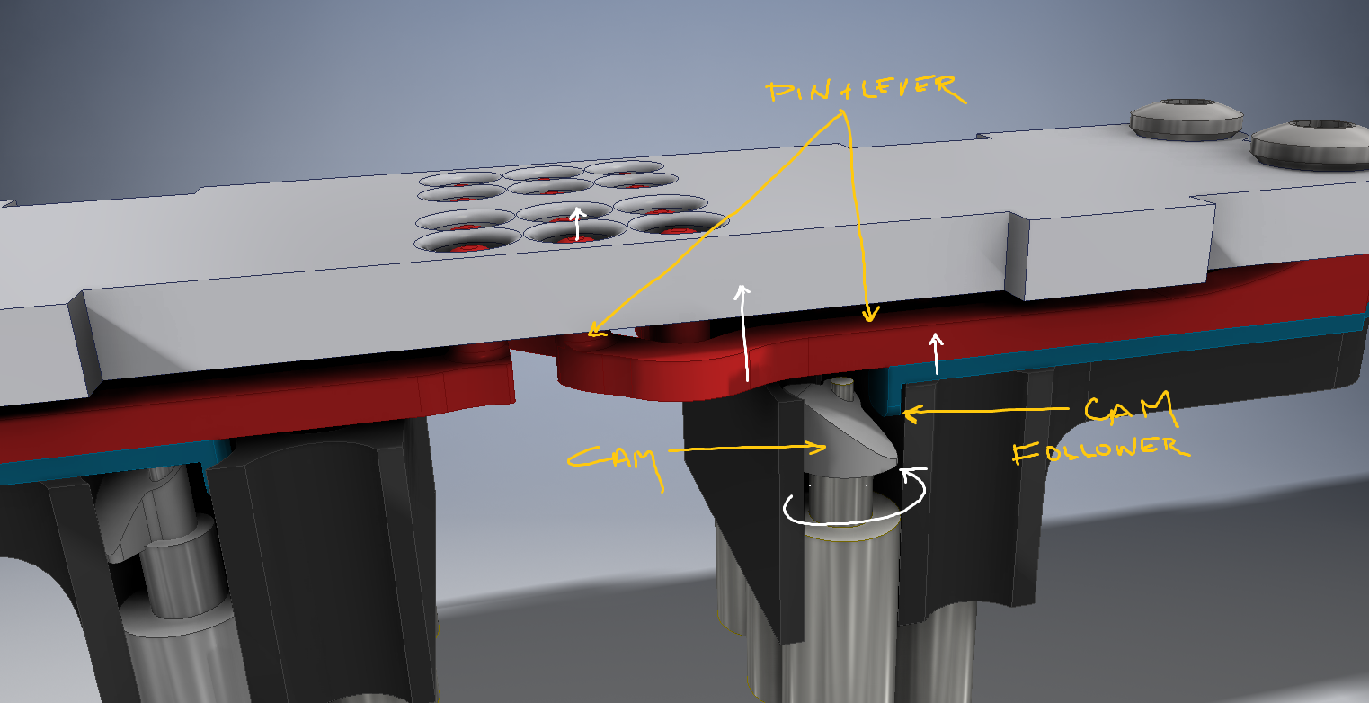
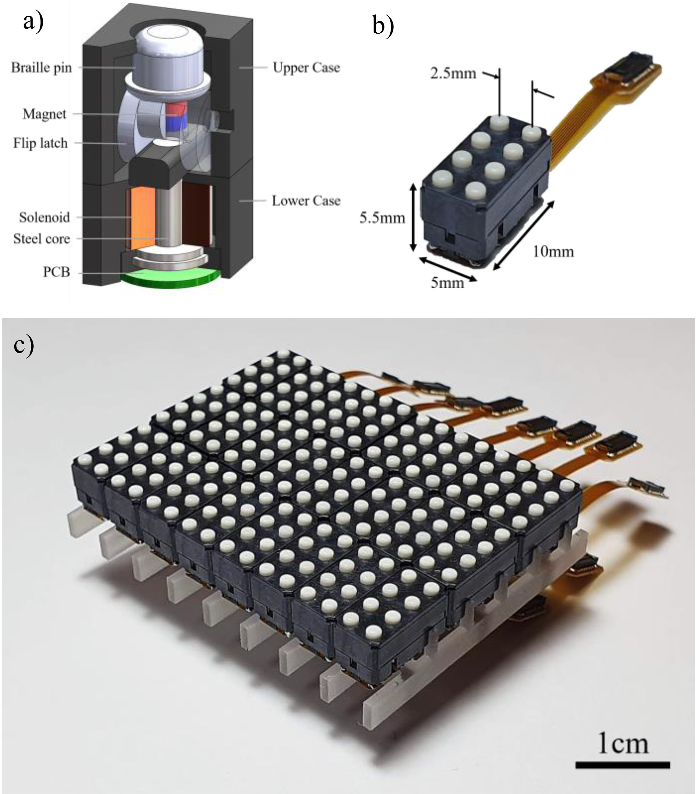
The current design is inspired by the work of Joonyeong Kim et al.: "Braille Display for Portable Device Using Flip-Latch Structured Electromagnetic Actuator"
![]()
The design was changed with the intention to have all parts 3D Printable and overcoming some of the challenges in the design:
- Interference of magnets with each other.
- A drive system adapted from Flip Dot displays to keep the electronics low cost and improve the refresh rate.
- Prevent the action of gravity causing the pins to fall out when used in other orientations.
- Redesign coil and coiling procedure to lower the cost of the electromagnet.
Other References:
MOLBED 2 project, and the manufacturing processes used for winding the coils.
![]()
Paul D'Sousa and his work https://www.youtube.com/@pgdsouza/videos
M. Benali-Khoudja, M. Hafez, and A. Kheddar, “VITAL: An electromagnetic integrated tactile display,” Displays, vol. 28, no. 3, pp. 133–144, 2007.
F. S. Cooper, "Research on reading machines for the blind" in Blindness Modern Approaches to the Unseen Environment, N. J., Princeton:Princeton University Press, pp. 512-543, 1950
H. Freiberger and E. F. Murphy, "Reading machines for the blind", IRE Trans. on Human Factors in Electronics, vol. HFE-2, pp. 8-19, March 1961.
Mohamed Benali-Khoudja, Moustapha Hafez, Jean-Marc Alexandre, and Abderrahmane Kheddar "Tactile interfaces: a state-of-the-art survey" SR 2004, 35th International Symposium on Robotics, 23-26 March, Paris France
M. Benali-Khoudja "Electromagnetically driven high-density tactile interface based on a multi-layer approach" November 2003 DOI:10.1109/MHS.2003.1249924 IEEE Xplore
T. Völkel, G. Weber, and U. Baumann, “Tactile graphics revised: The novel BrailleDis 9000 pin-matrix device with multitouch input,” in In International Conference on Computers for Handicapped Persons, 2008,
Electromechanical Refreshable Braille Module
Lowering the cost of Refreshable Braille Cells by using Electromagnetic Cam Actuators & 3D Printing