 Vijay
VijayI have been working with braille for about 3 years now. My first attempt at a prototype used a dot-matrix printer head: http://www.angadmakes.com/my-portfolio/virtual-brailler
At Makerfaire Bangalore, I met Paul D'souza and was amazed by his innovative designs for refreshable braille displays. One of his designs used these vibrator motors.
Im looking to build on that brillant idea and build a system that is more robust and can be understood and reproduced and improved by people all over the world for the visually impared , similar to how the open source prosthetics movement have helped so many amputees.
The method of working is as follows:
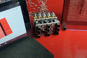
Motor+Cam :
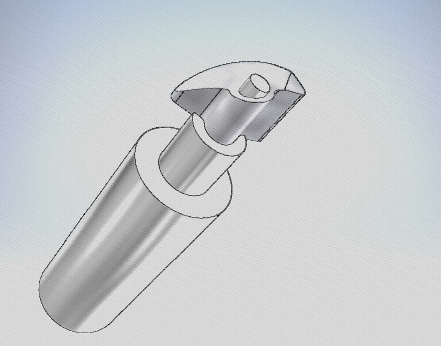
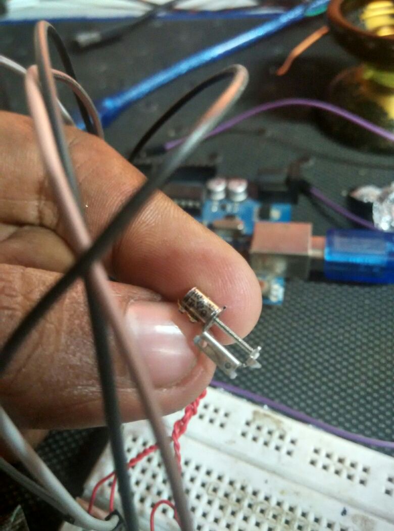
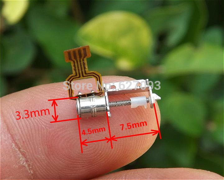
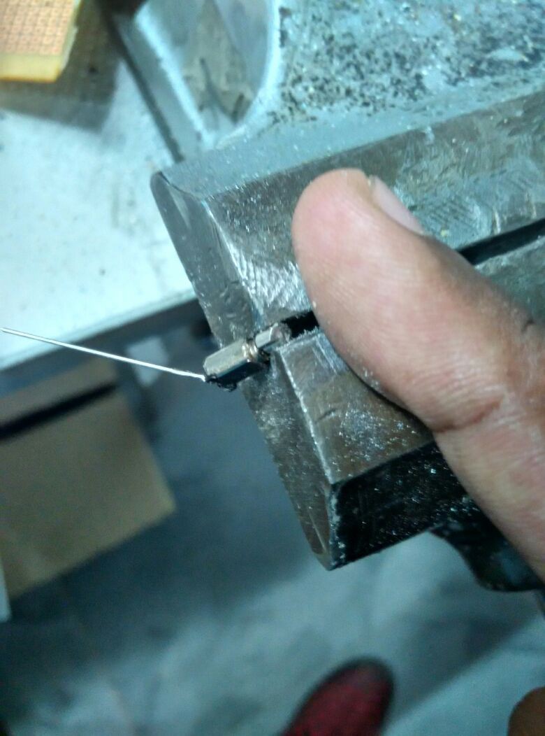
The heart of the mechanism is a series of pico-motors that are commonly used as vibration motors with a weight on the end.
We modify the weight to have a profile similar to the above so that is may act like a cam, when shaft axis is verticle.
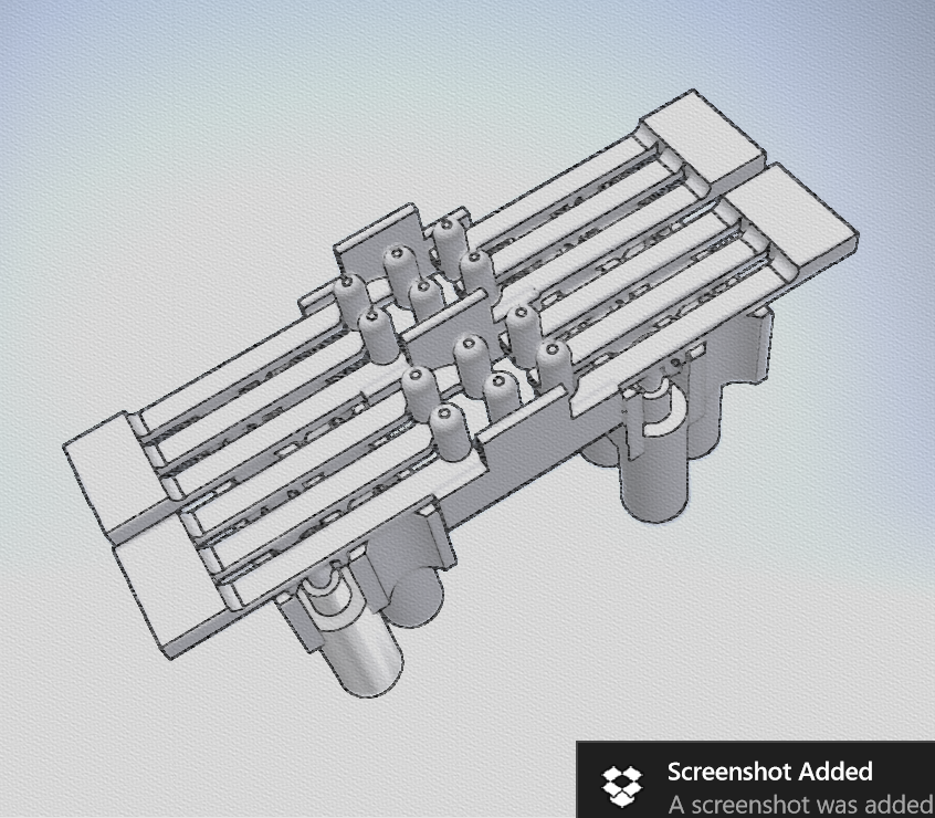
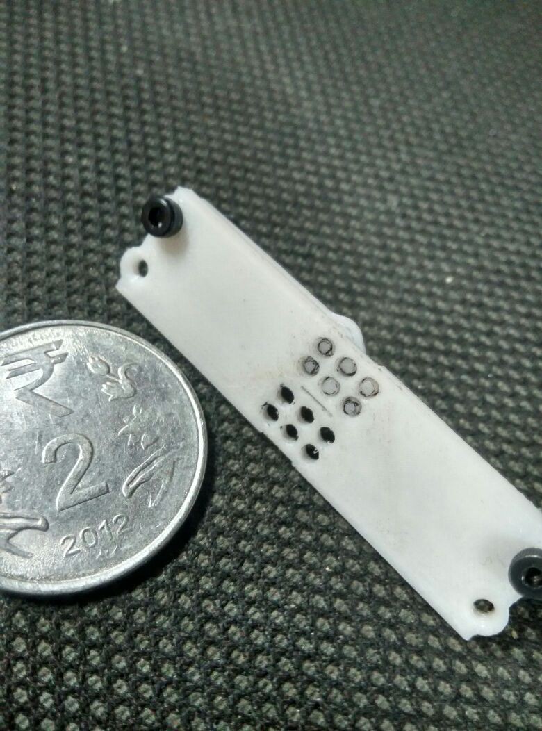
Motor holder + Stoppers:
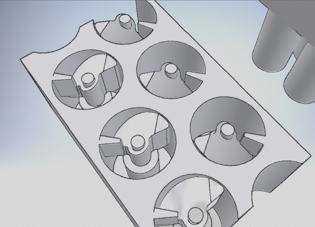
The motor holder holds all the motors in the appropriate positions to actuate the pins. There are stoppers that prevent the cam from rotating continuously that are integrated into the design.
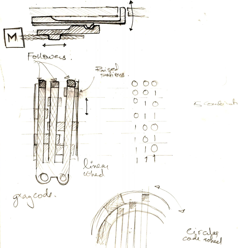
At the particular position where the cam followers are placed, depending on the rotation of the motor, the cam follower will he higher, when motor rotates one direction, and is lower in the other. The stopper make the motors behave in a "binary" fashion. The functioning will become clearer once the cam follower is explained.
Cam follower + Lever + Spring + Pins:
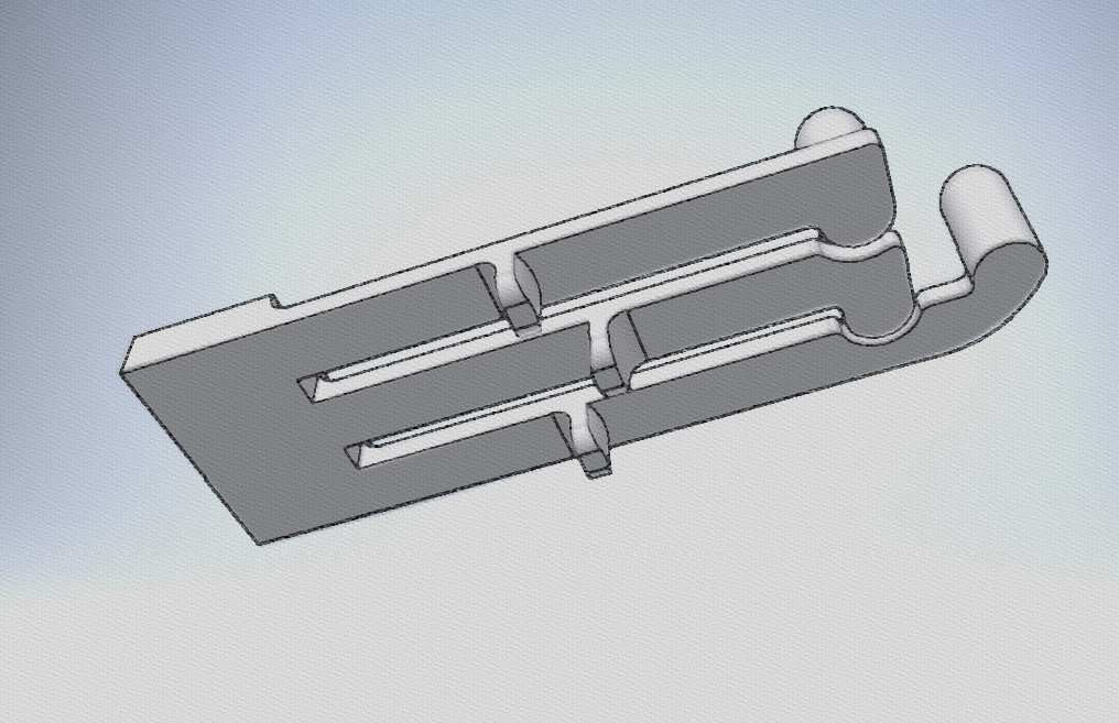
The cam followers, that will be riding on the motor's cam is shown in the first image( the three projections). The cam follower is attached to the lever bar, that is fixed on one end ( the large rectangular part). The level bar has the braille pins on the other end.
The material used for this part would be ABS, or Nylon, that would be slightly flexible without causing fatigue.
Thus the movement of the cam, wold cause the cam follower to move up, that flexes the lever pushing the braille pin upwards and the lever is displaced from its natural position. when the cam causes the cam follower to fall, the level bar falls back to its natural position and thus acts like a spring.
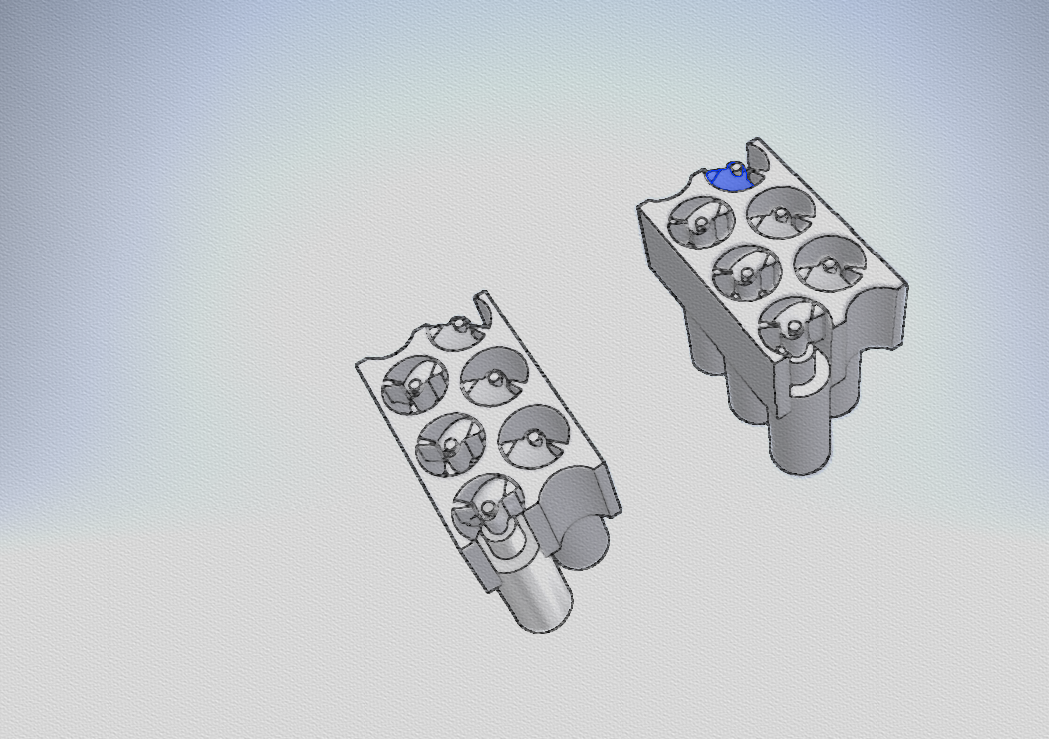
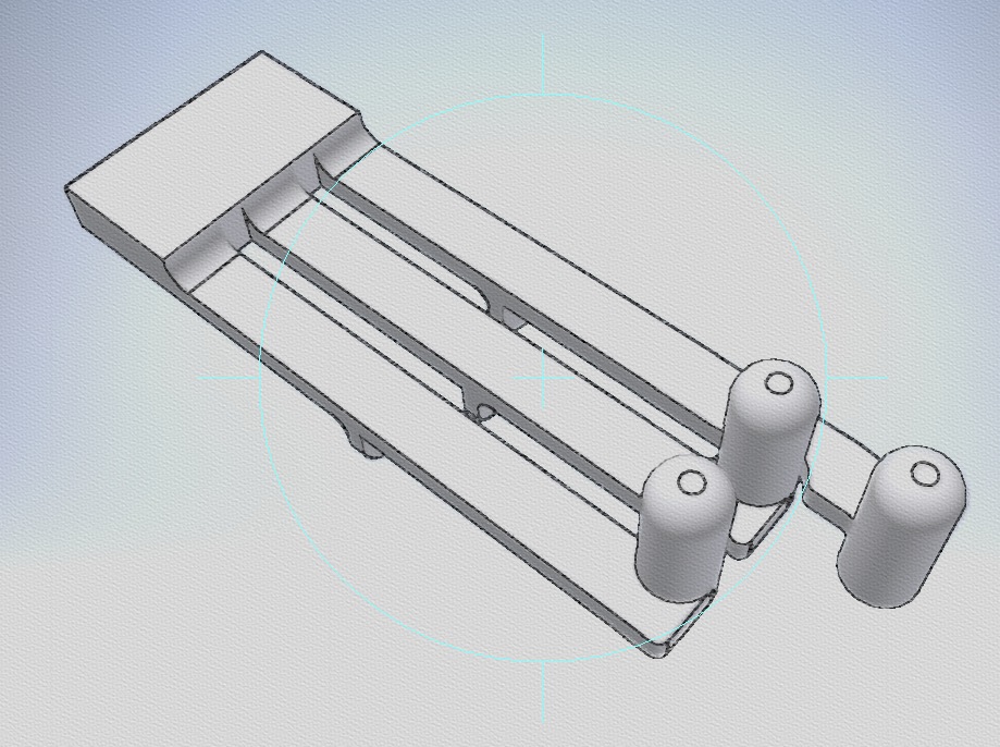
Everything is assembled in the above fashion. Two lever arrangements and six motors make up a single braille cell.
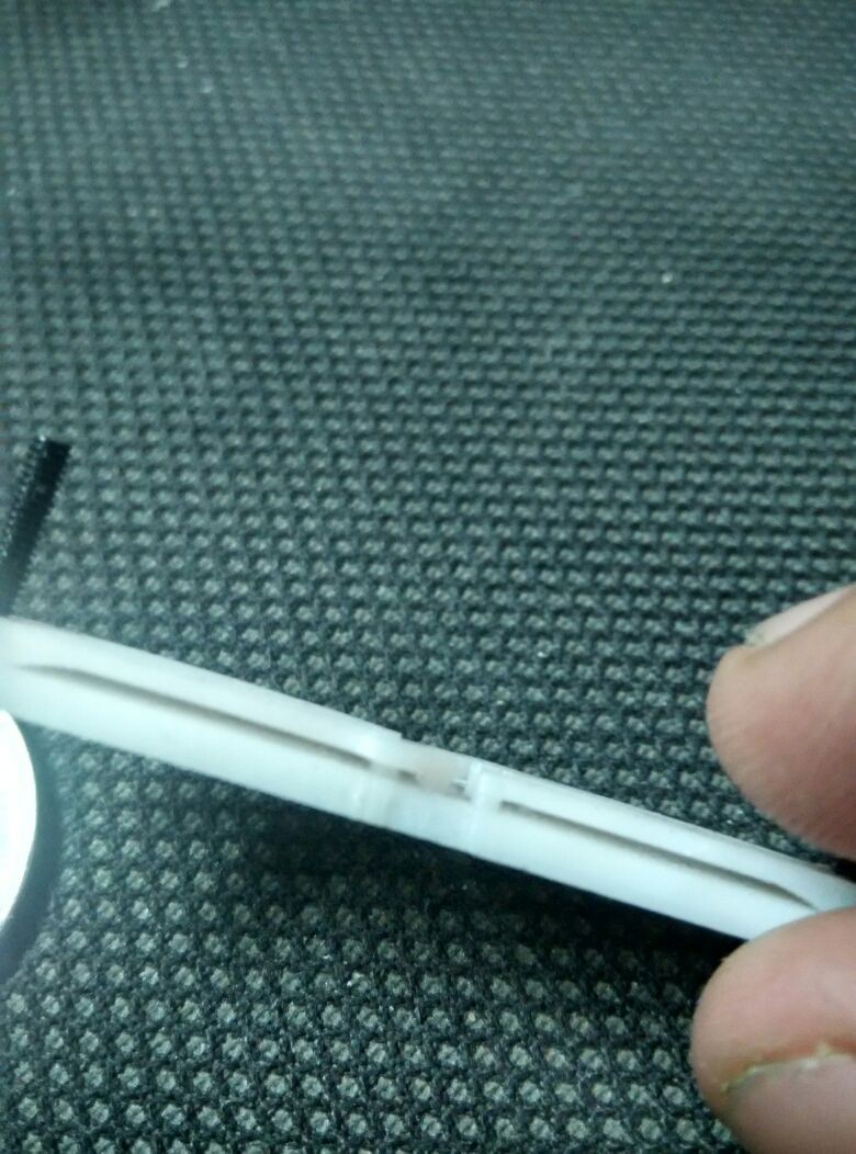
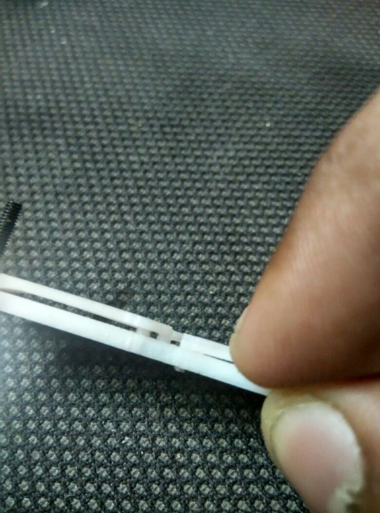
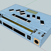
Faceplate+ Pin Guide:
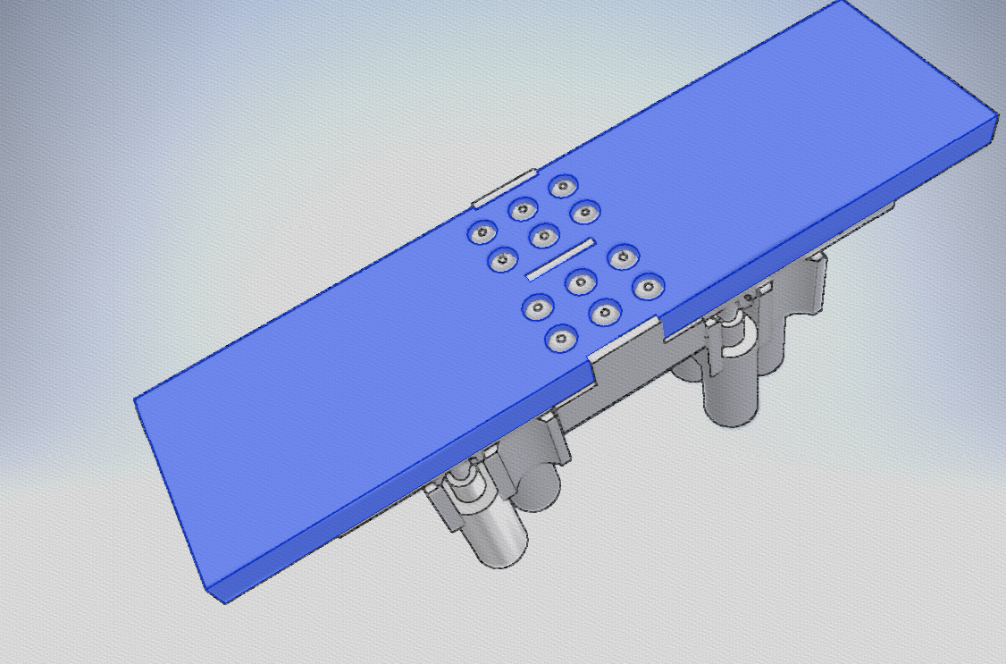
The faceplate forms the surface on which the pins pop out.
One module contains two refreshable braille cells( like above).Modules will be linked together to make a full braille display. i.e, for a 20 character refreshable braille display, 10 modules would be used.
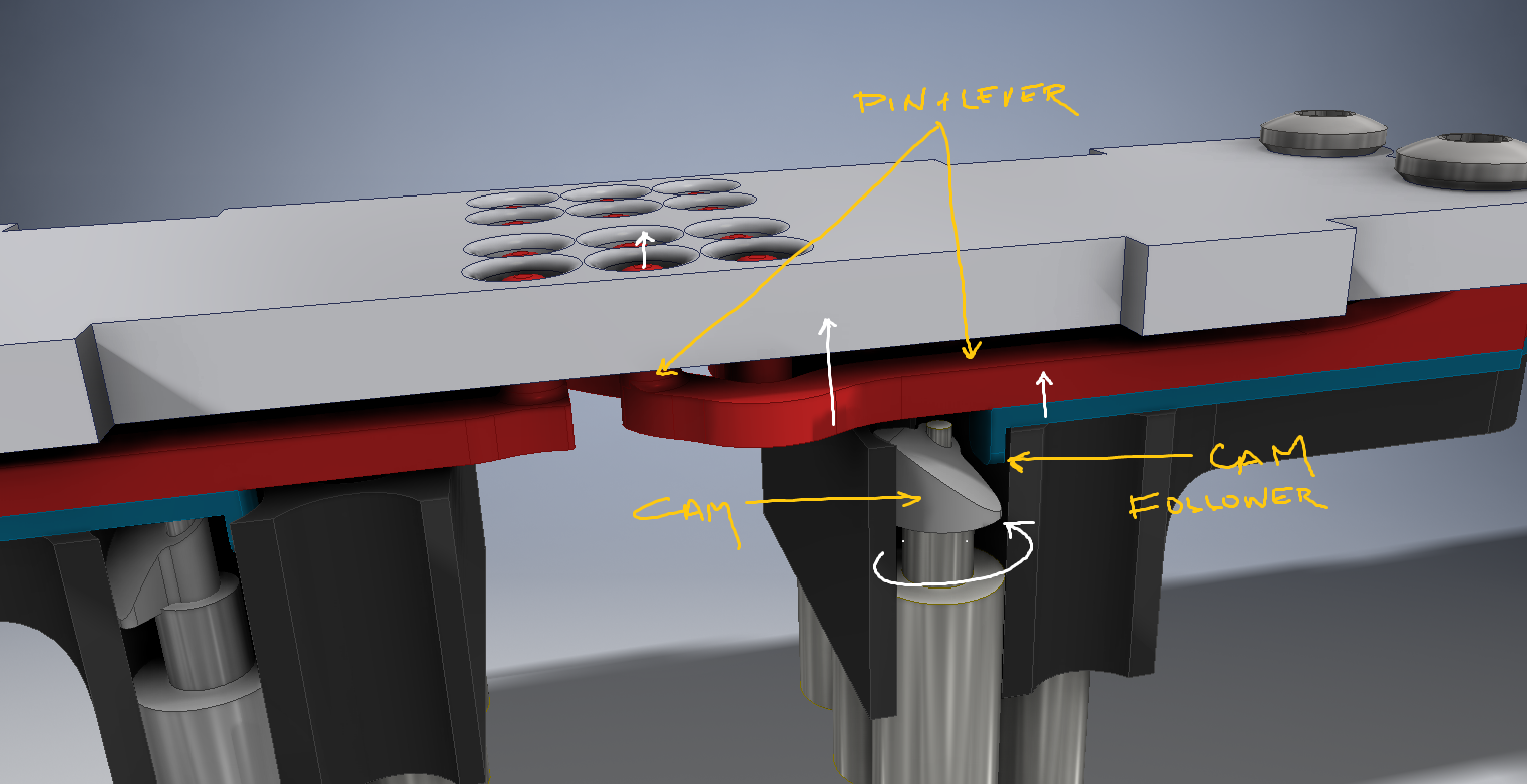
The below image illustrates the working better. the white arrows indicate direction of motion.


 Jeroen Delcour
 hugs
hugs
This is going on now for a few years...
For driving many stepper motors, when each has a driver chip you need step and direction pulses. I think you can drive all the direction inputs from a singe uC pin All motors would then turn in the same direction (or at least in a pre-determined direction) and you only have to provide step pulses for each of the motors. This can be handled by a single big uC.
You have also directly driven stepper motors from uC pins. If you need more current you can parallel multiple pins (needs careful programming). Driving many motors would overheat a big CPU, but you can have some serial protocol and a bunch of small uC's that each drive 1 to 4 or so motors directly from their I/O pins. Current consumption can be made with series resisters on some of the I/O pins. Drive all pins if you need torque, and only the pins with the series resistors for the hold current.