 Kevin Santo Cappuccio
Table of Contents (bolded ones are in this project log)
- General terms - the names I've decided to call things
- What's being stored - how the overall state is stored
- Pathfinding - how we find valid paths for each connection
- Controlling the switches - how we send that data to the CH446Qs
- LEDs - how we choose unique colors for each net
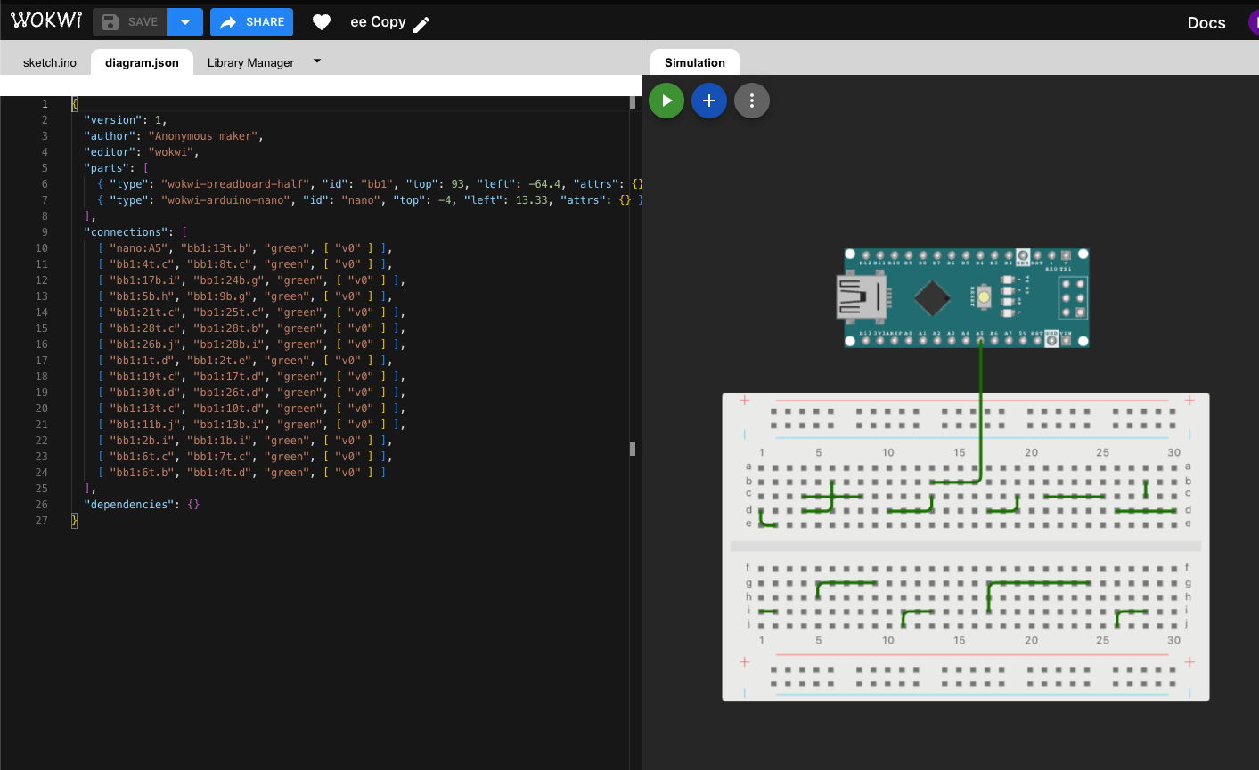
- The Wokwi bridge app - how we scrape the Wokwi page for updates
If you're wondering why you feel a strange sexual attraction to this board, I can give you a hint...
I didn't want to do the LEDs at first because it seemed a bit out-of-scope. But after using the prototype board without them, I found that it involved a lot of counting rows to find where you're connecting things. And that gets pretty tedious.
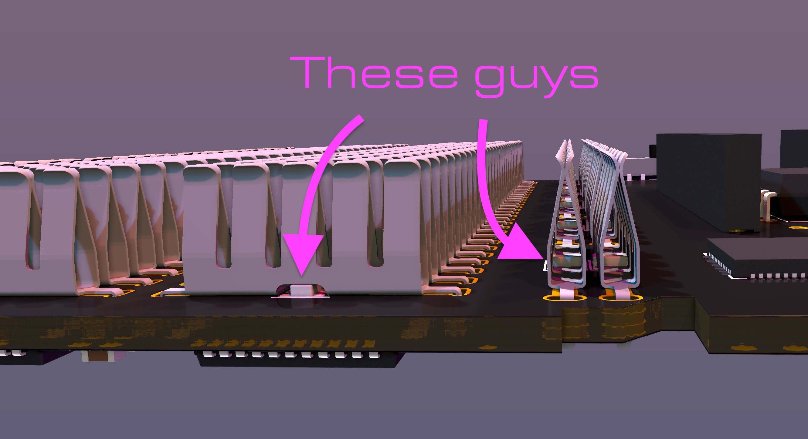
Around the same time, I had ended my month-long search for anyone who sells just the metal spring clips from a breadboard and resigned to having custom spring clips made by Shenzhen Fulimei Technology Co. LTD.
Hot tip for makers that want a bunch of some thing custom made using a non-so-common process: put your drawings and requirements up on made-in-china.com, you'll get a ton of quotes within days and just pick your favorite.
I'm glad I did, because using this thing is sooo much smoother now, you really only have to look at the board for the first connection and then everything else can just be counted as an offset from there. Also, the new versions of the breadboard shell have every 5th embossed number raised (which is actually super weird on breadboards because they count from 1, so there's 3 holes between 1 and 5, and 4 holes between the rest, enjoy being bothered by that forever) which makes it even easier to locate where you're connecting stuff.
How the colors are chosen
It would be really cool if the colors would correspond to the colors in the Wokwi diagram, but there's a couple of problems with that.
First:
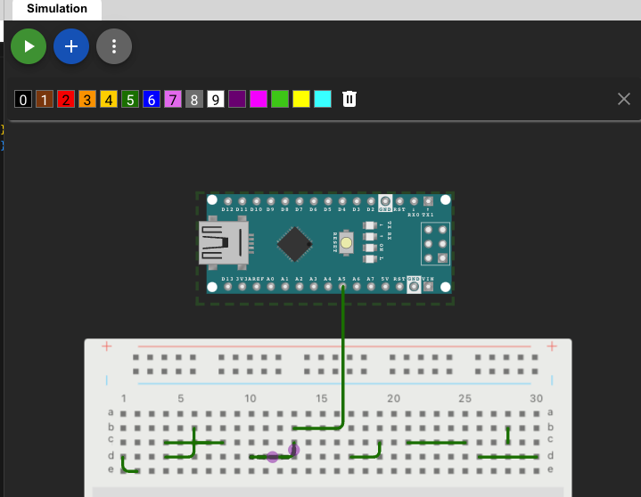
All the wires default to green, and having to select a unique color for each wire is kind of a pain in the current version of Wokwi. I know they'll eventually work on something to change this, but their voting system of which features they should work on next shows it's a fairly low priority.
The other issue is this:
Currently, they only support 15 HTML colors. So having only 15 different possible nets with unique colors (fewer, because black, grey, and brown wouldn't really show up on RGBs)
So we're just gonna pick our own colors.
The special nets have hard-coded colors, they are as follows:
  rgbColor specialNetColors[8] = {
  {00, 00, 00},
   {0x00, 0xFF, 0x30},    //GND     - Green
   {0xFF, 0x41, 0x14},    //5V     - Red leaning towards orange {0xFF, 0x10, 0x40},    //3.3v    - Red leaning towards purple
   {0xeF, 0x78, 0x7a},    //DAC 0-5V- Pinkish White  (changes brightness and hue based on output magnitude)
   {0xeF, 0x40, 0x7f},    //DAC +-8V- Purplish White (changes brightness based on output magnitude, hue for positive or negative)
   {0xFF, 0xff, 0xff},    //Current Sense+ - Yellow
   {0xff, 0xFF, 0xff}};   //Current Sense- - Blue

   rgbColor railColors[4] = {
    {0xFF, 0x32, 0x30},    //GND - Green
    {0x00, 0xFF, 0x30},    //5V - Red
    {0xFF, 0x32, 0x30},    //GND - Green
    {0x00, 0xFF, 0x30}};   //5V - Red
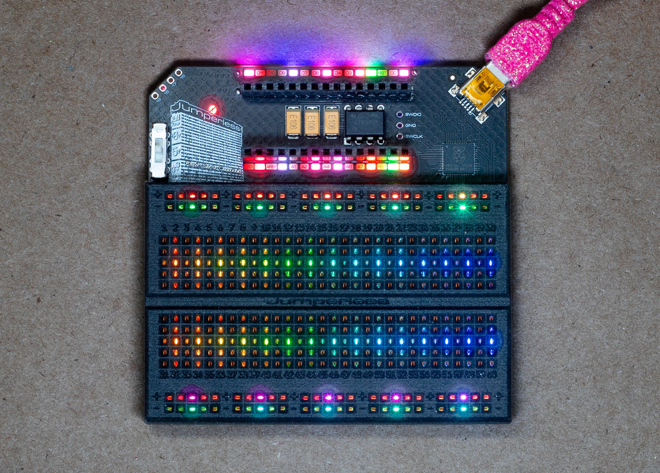
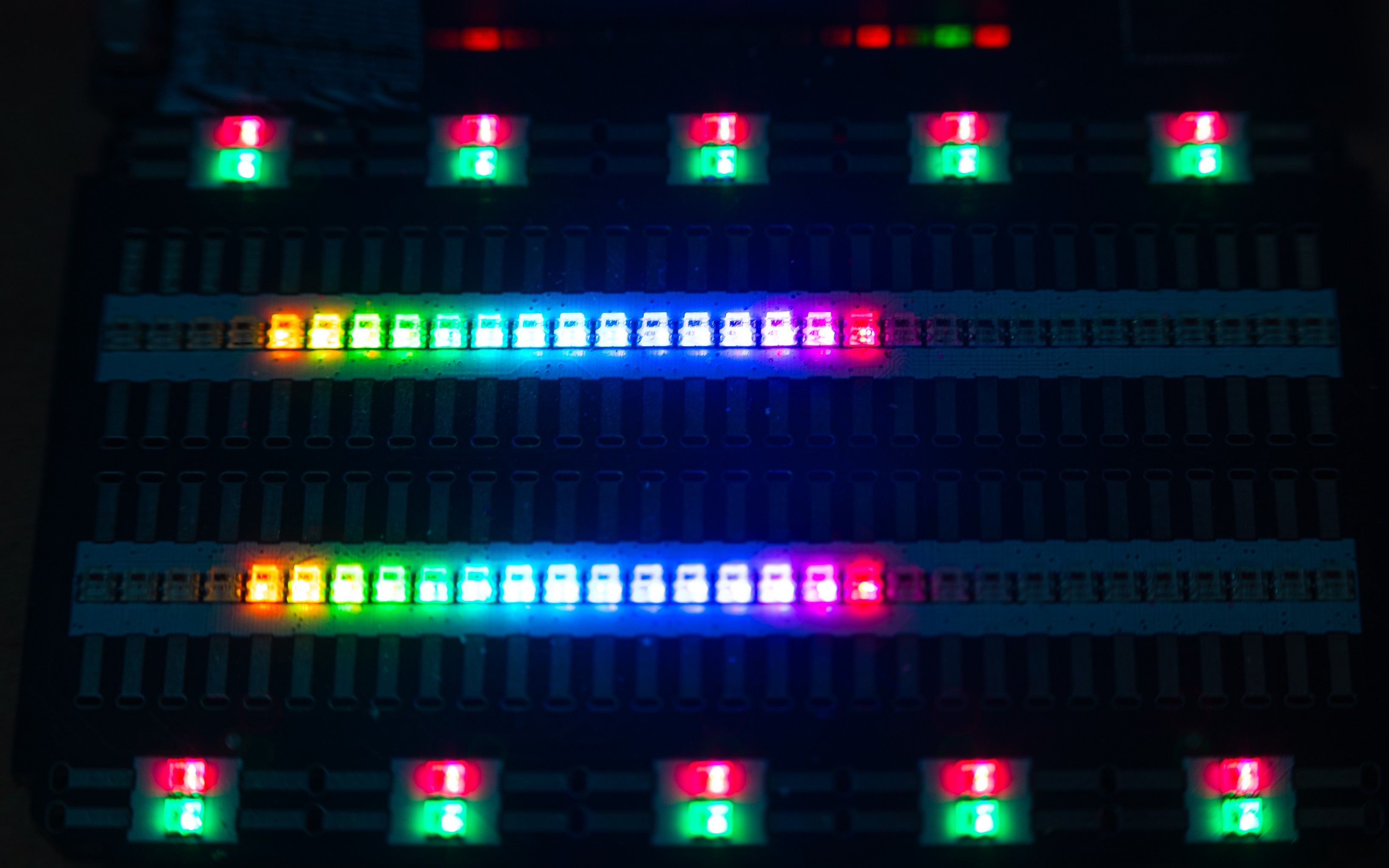
Here's what those look like:
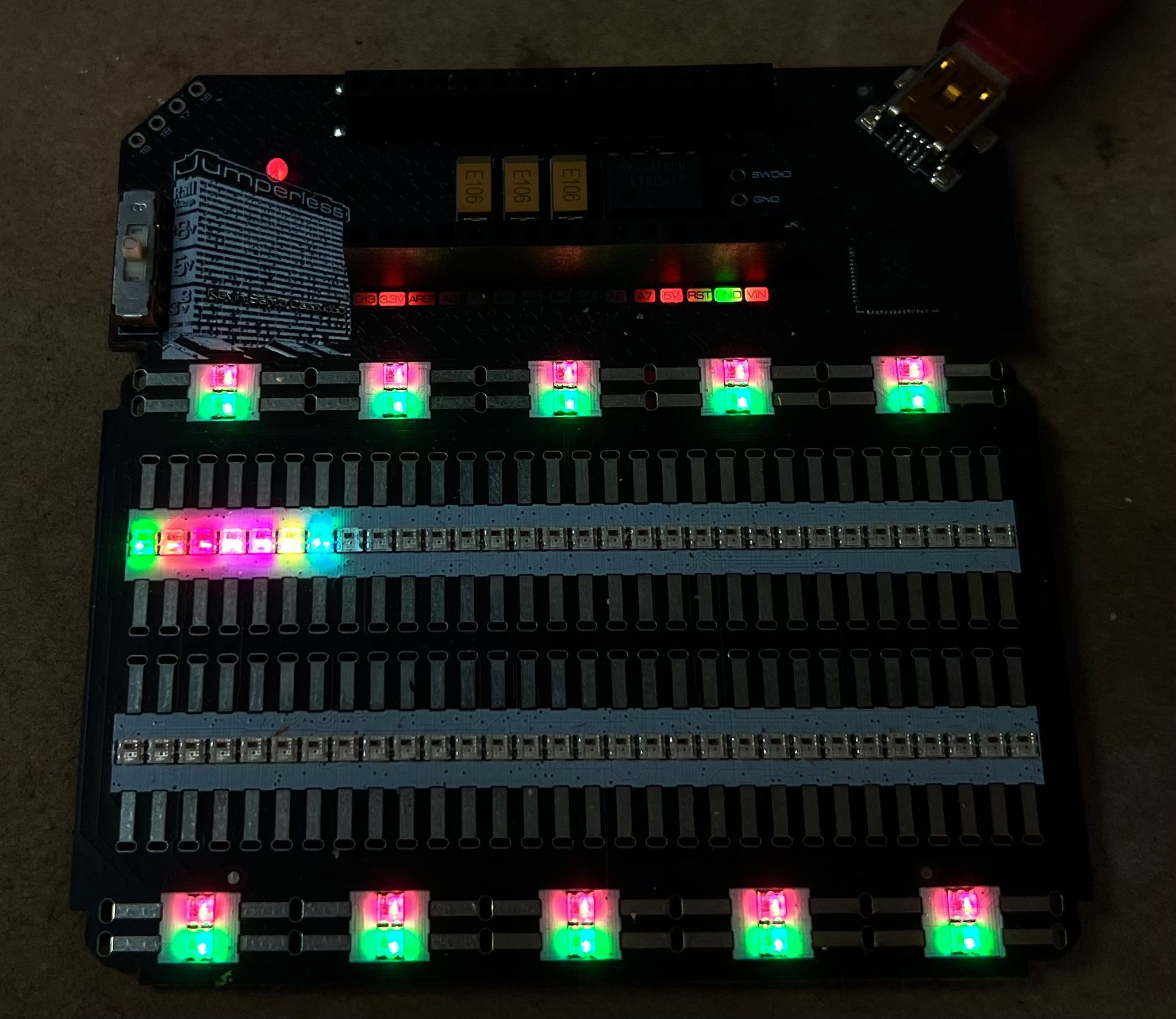
Note the bottom rail is 3.3V, top rail is 5V. pot1-sig is DAC 0, pot2-sig is DAC1.
The colors are saved at full brightness and scaled down to the default brightness or the brightness you set in the menu when they're displayed.
For the other nets, here's the general algorithm:
- Get the number of unique nets and divide that by 255 (that's the full color wheel in the NeoPixel Library) to get a color distance
- Check if the hue at (color distance * 1) is the too close to any of the special nets
- If it is, add 1 to the number of unique nets and calculate a new color distance, then try again with an offset (color distance/2)
- If not, set that hue for the net and check the next net at (color distance * 2) etc...
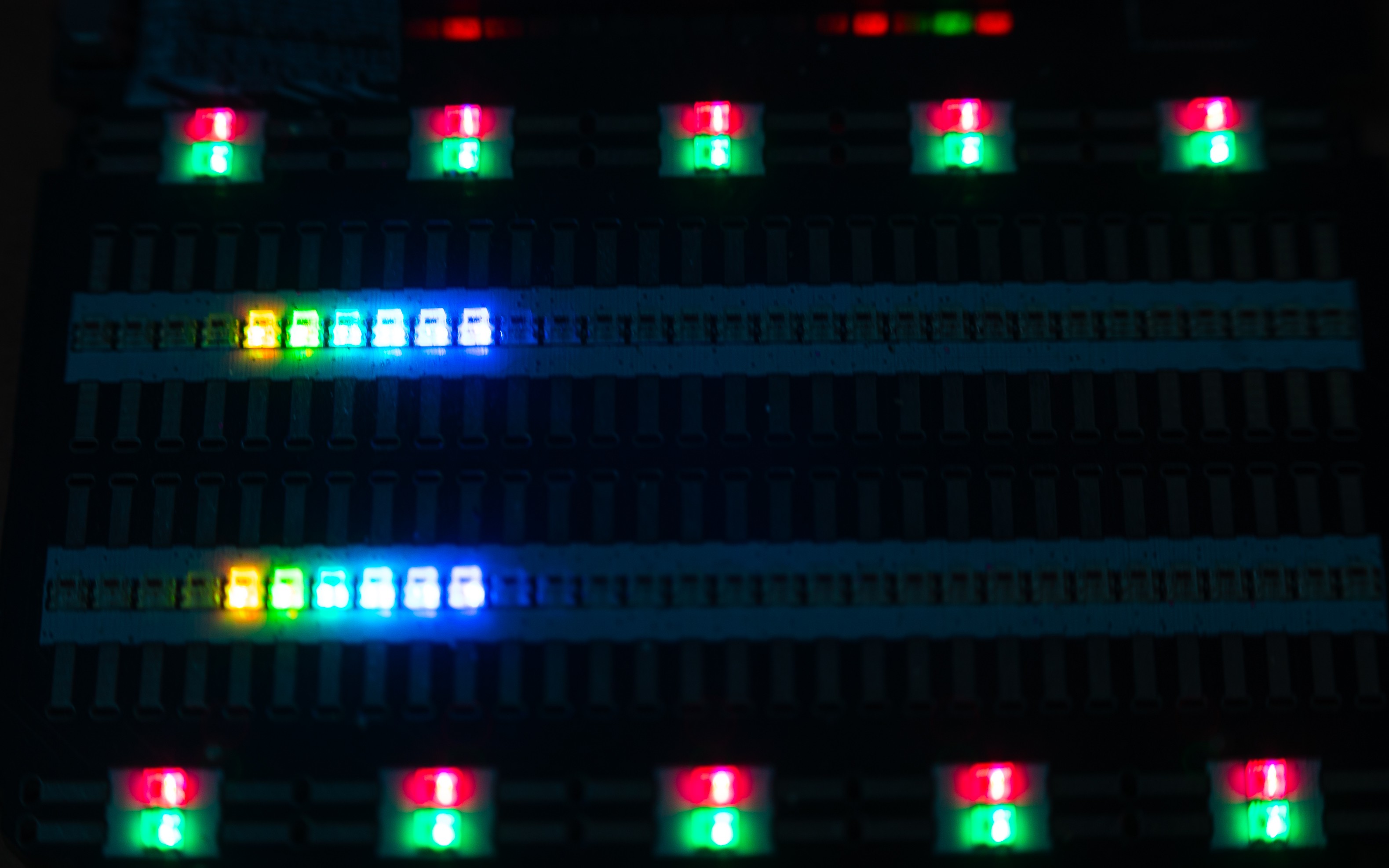
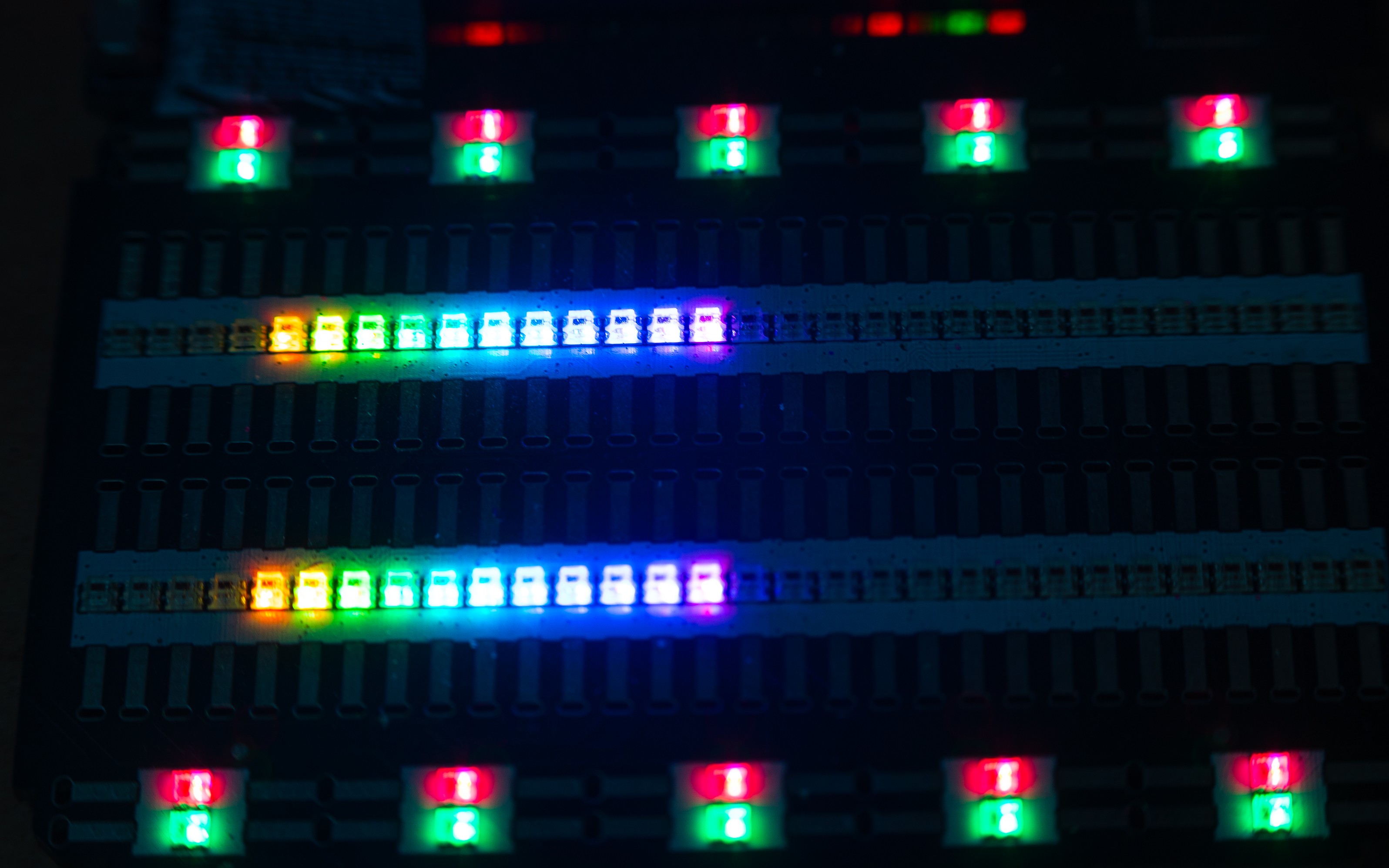
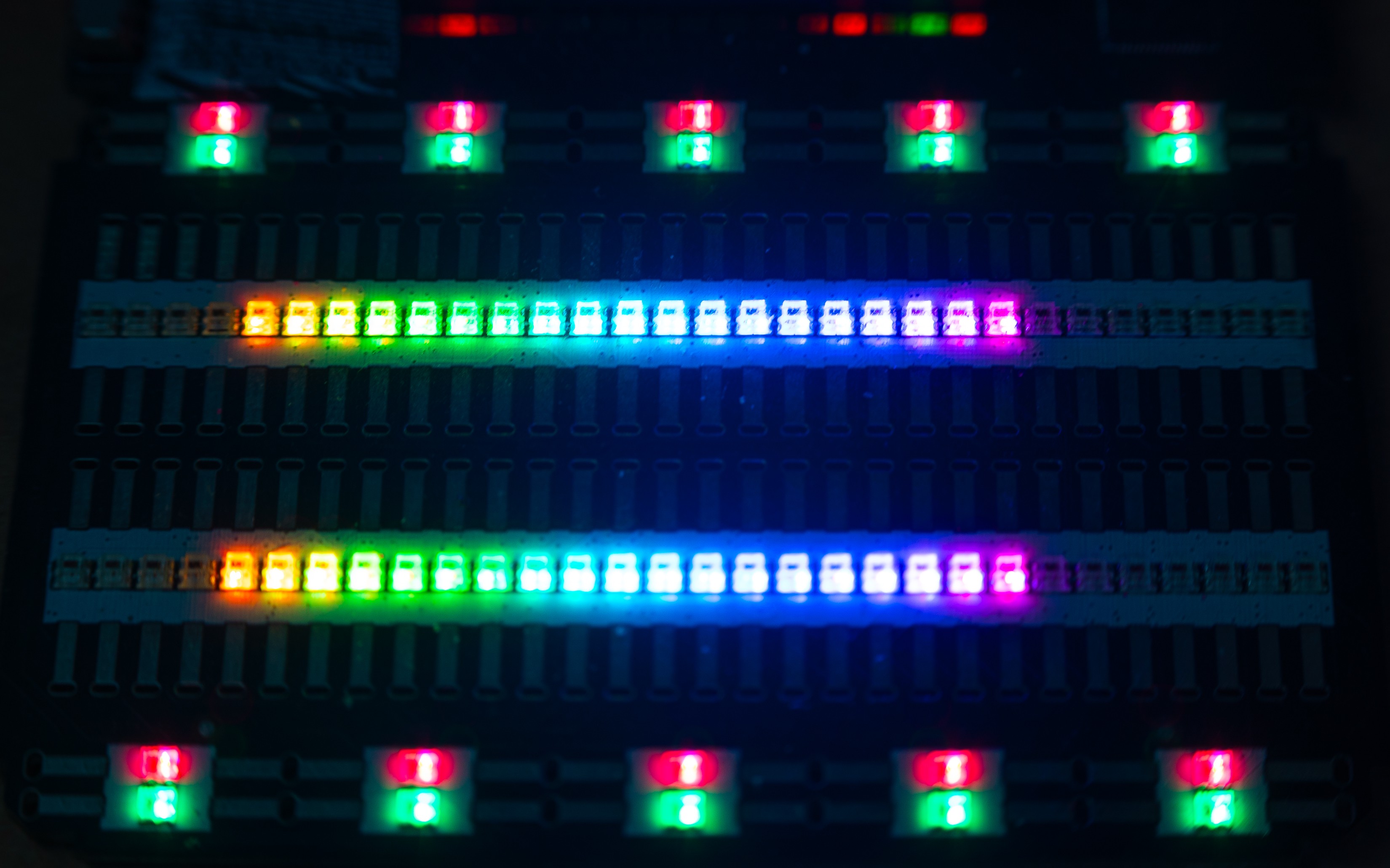
Here's how that plays out:
Correcting for FR4
For the colors to be useful as an indicator, you should be able to recognize a color is the same whether you're directly looking a the LED on the breadboard or it's passing through the yellowish PCB around the Nano Header.
This turned out to be surprisingly complicated, I basically spent 2 days just tweaking the values until it looked right. Why it was so complex is that the yellowish filtering only affects some colors and basically doesn't do anything to others (except making them slightly dimmer).
The shifts are defined as constants in LEDs.h
#define PCBEXTINCTION 30 //extra brightness for to offset the extinction through pcb


#define PCBREDSHIFTPINK -18 //extra hue shift to offset the hue shift through pcb

#define PCBGREENSHIFTPINK -25

#define PCBBLUESHIFTPINK 35


#define PCBREDSHIFTBLUE -25 //extra hue shift to offset the hue shift through pcb

#define PCBGREENSHIFTBLUE -25

#define PCBBLUESHIFTBLUE 42
Here's that whole function if you want to try figuring it out
The shifting is different depending on which side of the spectrum you're on, hence the shifts for the blue and pink separately. I was going to do like a continuous blending between the two, but it turns out it looks better with just a cutoff at a certain hue.
struct rgbColor pcbColorCorrect(rgbColor colorToShift)
{

    uint8_t redShift = 0;
    uint8_t greenShift = 0;
    uint8_t blueShift = 0;

    int testNeg = 0;

    struct rgbColor colorToShiftRgb = colorToShift;

    struct hsvColor colorToShiftHsv = RgbToHsv(colorToShiftRgb);

    // colorToShiftHsv.v += PCBEXTINCTION;

    if (colorToShiftHsv.h > 100 && colorToShiftHsv.h < 150)
    {

        if (PCBREDSHIFTBLUE < 0)
        {
            testNeg = colorToShiftRgb.r;
            testNeg -= abs(PCBREDSHIFTBLUE);

            if (testNeg < 0)
            {
                colorToShiftRgb.r = 0;
            }
            else
            {

                colorToShiftRgb.r = colorToShiftRgb.r - abs(PCBREDSHIFTBLUE);
            }
        }
        else
        {

            colorToShiftRgb.r = colorToShiftRgb.r + abs(PCBREDSHIFTBLUE);

            if (colorToShiftRgb.r > 254)
            {
                colorToShiftRgb.r = 254;
            }
        }

        if (PCBGREENSHIFTBLUE < 0)
        {

            testNeg = colorToShiftRgb.g;
            testNeg -= abs(PCBGREENSHIFTBLUE);

            if (testNeg < 0)
            {
                colorToShiftRgb.g = 0;
            }
            else
            {
                colorToShiftRgb.g = colorToShiftRgb.g - abs(PCBGREENSHIFTBLUE);
            }
        }
        else
        {
            colorToShiftRgb.g = colorToShiftRgb.g + abs(PCBGREENSHIFTBLUE);
            if (colorToShiftRgb.g > 254)
            {
                colorToShiftRgb.g = 254;
            }
        }

        if (PCBBLUESHIFTBLUE < 0)
        {

            testNeg = colorToShiftRgb.b;

            testNeg -= abs(PCBBLUESHIFTBLUE);

            if (testNeg < 0)
            {
                colorToShiftRgb.b = 0;
            }
            else
            {
                colorToShiftRgb.b = colorToShiftRgb.b - abs(PCBBLUESHIFTBLUE);
            }
        }
        else
        {
            colorToShiftRgb.b = colorToShiftRgb.b + abs(PCBBLUESHIFTBLUE);
            if (colorToShiftRgb.b > 254)
            {
                colorToShiftRgb.b = 254;
            }
        }

    }
    else if (colorToShiftHsv.h >= 150 && colorToShiftHsv.h < 255)
    {

        if (PCBREDSHIFTPINK < 0)
        {
            testNeg = colorToShiftRgb.r;
            testNeg -= abs(PCBREDSHIFTPINK);

            if (testNeg < 0)
            {
                colorToShiftRgb.r = 0;
            }
            else
            {

                colorToShiftRgb.r = colorToShiftRgb.r - abs(PCBREDSHIFTPINK);
            }
        }
        else
        {

            colorToShiftRgb.r = colorToShiftRgb.r + abs(PCBREDSHIFTPINK);

            if (colorToShiftRgb.r > 254)
            {
                colorToShiftRgb.r = 254;
            }
        }

        if (PCBGREENSHIFTPINK < 0)
        {

            testNeg = colorToShiftRgb.g;
            testNeg -= abs(PCBGREENSHIFTPINK);

            if (testNeg < 0)
            {
                colorToShiftRgb.g = 0;
            }
            else
            {
                colorToShiftRgb.g = colorToShiftRgb.g - abs(PCBGREENSHIFTPINK);
            }
        }
        else
        {
            colorToShiftRgb.g = colorToShiftRgb.g + abs(PCBGREENSHIFTPINK);
            if (colorToShiftRgb.g > 254)
            {
                colorToShiftRgb.g = 254;
            }
        }

        if (PCBBLUESHIFTPINK < 0)
        {

            testNeg = colorToShiftRgb.b;

            testNeg -= abs(PCBBLUESHIFTPINK);

            if (testNeg < 0)
            {
                colorToShiftRgb.b = 0;
            }
            else
            {
                colorToShiftRgb.b = colorToShiftRgb.b - abs(PCBBLUESHIFTPINK);
            }
        }
        else
        {
            colorToShiftRgb.b = colorToShiftRgb.b + abs(PCBBLUESHIFTPINK);
            if (colorToShiftRgb.b > 254)
            {
                colorToShiftRgb.b = 254;
            }
        }
    }
    return colorToShiftRgb;
}
I do a lot of swapping between RGB and HSV in the code, if I was working with a slower microcontroller, I might have been more strict about it, but on the RP2040 it handles it just fine.
How it sends the data to the LEDs
Jumperless just uses the standard Adafruit_NeoPixel library, one thing to note about it is that it's blocking. So when you're sending data to LEDs, it stops your other code.
I didn't even notice this until I was working on code to have the DACs change hues depending on the measured output. Like this:
Note that DAC 1 (right) is an actual measurement from ADC 3, If you look closely you can see a bit of "wobbliness," that's from taking real measurements of the output. For now DAC 0 (left) is just showing what it should be set to, but it's super easy to change that in the code.
So, to get around the blocking nonsense, I run the LEDs from core 2, just like the CH446Qs. So if anything on core 1 wants to update the LEDs, it just sets showLEDsCore2 = 1 and the second core will see that and do its thing.
void loop1() // core 2 handles the LEDs and the CH446Q8
{


  if (showLEDsCore2 >= 1)
  {
    int rails = showLEDsCore2;

    //showNets();
    if (rails == 1)
    {
     lightUpRail();
    }
   delayMicroseconds(5200);


    leds.show();
    delayMicroseconds(9200);
    showLEDsCore2 = 0;
  }

  if (sendAllPathsCore2 == 1)
  {
    delayMicroseconds(9200);
    sendAllPaths();
    delayMicroseconds(2200);
    showNets();
    delayMicroseconds(9200);
    sendAllPathsCore2 = 0;
  }


  if (logoFlash == 2)
  {
    logoFlashTimer = millis();
    logoFlash = 1;

  }

  if (logoFlash == 1 && logoFlashTimer != 0 && millis() - logoFlashTimer > 600)
  {
    logoFlash = 0;
    logoFlashTimer = 0;
    //lightUpRail();
    leds.setPixelColor(110, 0x550008);
    leds.show();
  }


}
This allows the LEDs to update quickly and not cause weird glitches in the DAC outputs.
That's all I got about the LEDs, if you want me to be clearer about something, let me know and I'll add to this log.
Next part - The Jumperless Wokwi Bridge App or: How I Learned Python and Went From Wishing I Knew Python to Wishing I Didn't
Discussions
Become a Hackaday.io Member
Create an account to leave a comment. Already have an account? Log In.
So rad! The custom clips are just next level. I see myself ordering some in the near future.
Are you sure? yes | no