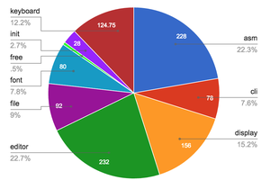
• V02 - WIP

    Michael Möller08/25/2023 at 08:36 0 comments

    Workflow:

    • Edit the text source with extended/corrected function.
    • "Handassemble", ie write the HEX codes and calculate offsets in same text file
    • Reformat (a copy of) the text file to conform to the V01 format (one line of HEX digits)
    • Run the V01 assembler ON THE BADGE to create the binary from the V01 format to create the V02 binary
    • Reformat (another copy of) the text file to conform to the V02 format (zero or one HEX per line, whitespace, lowercasee allowed)
      • Easier alternative: create a shorter dummy test file (nonsense code) in V02 format
    • Load the V02 and debug, by feeding a file in V02 format version

    Rinse and repeat

  • V01 Released

    Michael Möller08/24/2023 at 15:45 0 comments

    V01 working

    ...and there was rejoicing and dancing in the streets :-)

    I have updated all the files with the V01 version, with this log update. (The syntax of the length prefix has changed, otherwise it is just bug fixes, w.r.t. to earlier design thoughts)

    This (proto)assembler takes the ASCII string of Hex codes, preceeded by a 4 hex digit count, and returns a valid binary load file. Due to the flow control problem a python program only feeds data when no output is expected.

    It is selfassembling in the sense that doing a save of the image, produces the same binary result as the assembler produces when fed it's source text (ie that ASCII hex file)

    I will now edit the V01 text file to V02, where I incorporate a minor but essential change, and then hand assemble and generate the ASCII hex file. This is fed to the assembler. It's output is then loaded, thus I am NOT using buttons to enter any code more. The Bootstrap Stage is thus done!

    V02 plans (and beyond)

    The first change is Whitespace ellimination. This allows the input file to have newline. There is also a need for some restructure, making it line oriented on the input, allowing for comments. The input routine and output routines will become a bit more "robust" (I hope).

    The second change (V03) is comments, ie everything after a ";" is ignored until newline. There is a design challenge with empty input lines, how the timing protocol will handle that.

    What comes next is undecided: (A) Make the assembly "two pass", ie the current V01 forms the basis of the 2nd pass, and 1st pass takes some text and converts it to the format for the 2nd pass. More work for the same output, but it is a prerequisite before doing labels. (B) Allow some mnemonics; initially a simple "HEX nnn", then add (f.ex.) "RET value", "NOP" (=MOV R8,R8).

    OK, ok, lets keep focused on the next step.

  • WTF :-( ?

    Michael Möller08/17/2023 at 13:32 0 comments

    I am going cra5y !

    It works sometimes, and not other times, for identical input.

    It is not initialization (I think) because the badge says everything (Registers, RAM etc) is zeroed on start of Run.

    I can see that sometimes when I enter a "A" on my terminal (PuttY) I receive two(!?) characters in the serial buffer on the badge, the first being the DC3 code.

    I did a pythonscript to slowly send characters and receive them (workaround for the Serial Bug flow control problem) and it works on the 1st run, but not on subsequent runs, unless I totally reboot everything. Again, it seems an extra DC3 sneaks in.

    Somewhere, the USB/Serial/Windows gets buggered on receiving the binary header? But receiving binary is essential. I do not have flowcontrol enabled. (DC3 is ^Q ie flowcontrol)

    Much later (update)

    It's been a long debugging session. There were multiple flaws, partially obscuring each other, so fixing one, just created a different error. The highlights (or should that be lowlights :-) ? ) :

    The serial interface on the badge is sensitive. It gets totally confused if you only take the high nibble, ie always take both. Likewise with writing. If you have confused it, you need to do a hard reset - the RUN does not clear it. (This was first tracked down when I put a logic analyzer on the serial, and saw that only the expected characters were sent)

    In order to workaround the duplex problem - that no characters are waiting to be read when sending - the simple driver program and the badge code have to agree. I wasted a lot of time on one assembler bug, that actually was an oversight in the protocol.

  • Debugging V01

    Michael Möller08/05/2023 at 14:01 0 comments

    Hooked up with a terminal emulation program and RX/TX to the badge, correct baud/parity/len and RAW mode and display binary, we should see the first part of header being produced (I only keyed in that part of the program.)

    Testing with ASCII HEX

    0400 generates two bytes saying we have 4 bytes, ie two instructions when they have been padded
    012 nonsense instructions, but choosen to verify correct Hex conversion
    AF0
    . EOT marker.
    This is of course put as a single line "0400012AF0."

    But I am saddled with the serial bug, I must enter one character on the keyboard when I see the badge code is looping for the next input character. I can enter 3 characters at a time (after the initial 4), without Input/Output serial clash.

    Sigh... so many errors. Some simple typos, offsets wrong, some stupid logic.

    The output routine was rewritten to buffer a half-byte to avoid using the Serial for output too soon. The checksum needed to include the length byte. Byte ordering in the output corrected.

    Entering the nonsense 2 instructions from above and then using built in "Save program to serial" I get the same output, as my program. Yeah!

    But that was a coincidence.....

  • V0.1 - step by step bootstrap

    Michael Möller08/05/2023 at 12:07 0 comments

    The code is written and is in V01.1.TXT. This is in a fictious simple assembler format. Now what?

    1. Hand assembly means I edit the text file and add the hex code for each. Also I add the location it will end up in, makes it easier when checking if entered everything.
    2. (Bitter) Experience means there will be errors, and adding one instructions means everything moves, so to minimize that, I add buffer regions with NOP instructions which can be overwritten without consequence.
    3. Where the code uses labels, like "JR GETLEN" the offset or absoulte value of the address can now be calculated and entered. See comments in the result V01.2.TXT
    4. Enter hexcodes via the buttons.

    To run the program some input is needed. Of course I can write a simple text file, but as the intention is that it should be able to self-assemble this code needs to be converted to the primitive format it currently uses.

    1. Remove everything execpt the hex code, one instruction per line.
    2. Note the linecount, double and adjust for any last empty line. Convert to Hex and enter that as a 4 hex digit number, BigEndian, at the front of the file.
    3. Join it all into one line. Result is V01.3.TXT

    But I was to lazy to key it all with the buttons, so I try to convert this into a loader binary file, using hex editing. (Notepad++ has an extension, your editor may have something, too) So instead of step 4 do:

    1. In ASCII mode of the editor; Revert back the single line and byte count, so one hex triplet per line
    2. Add a "0" in front, and a dash between the pairs.
    3. Swap the two pairs on each line
    4. Replace newline with a dash. This joins it all into one line again.
    5. In Hex mode of the editor; replace any pair by the value. F.eks. The first "30 39" hex pair (being "09" in ASCII) to a "09" value. Yes, this needs  potentially to be done for all 256 possible values, but only a small subset has been used, so this should still be less work. The dashes limit pairs to actual bytes. [After having done this 3 times, because of fumbling errors, I switched to button keying.]
    6. Remove the dashes. Check you have the number of bytes you noted previously.
    7. Add the prefix "00FF0FFA5C3" (in binary values) an the length from before, but remember to swap the bytes.
    8. Add the checksum. Calculating that by hand is tedious (remember we do not use a source computer if we are purists. In the real world the first hardware loader could probably surpress the checksum check.) But, as I gave up on trying this, it is academic.
    9. Upload.

    Bootstrap

    After keying the initial "proto-assembler" into the badge, I kan write, handassemble and reformat as described, any code and get it "assembled". Including a slightly better "assembler". That is what I mean by having boostrapped the assembler, or rather, the assembler development. The next few iterations are tedious, but it will gradually require less and less of handassembly and reformatting. 

    Interestingly enough, having manually keyed in the first version, I can use the save-to-serial feature to get the same loader file that it should generate - a nice verification

  • Just a few more hurdles before starting

    Michael Möller08/04/2023 at 10:13 0 comments

    The loader binary format was reverseengieered by examining code example https://github.com/Hack-a-Day/2022-Supercon6-Badge-Tools/blob/main/examples/Hackaday-dice-roll/dice_roll.asm - later I found it is reasonably documented in the UserManual for the badge (almost as a footnote under the DIR/LOAD command):

    1. Header 6 bytes: 00 FF 00 FF A5 C3
    2. Program length 2 bytes (in 16-bit words, Low byte first): NN NN
    3. Program "NN 0N"×Program Length (Low first): NN 0N, NN 0N, ...
    4. 16-bit Checksum 2 bytes (items 2 and 3 only, Low first): NN NN

    Problem 1, The code length is first known after the 1st pass (before generating the header), but I do not have that yet in these earlier bootstrap versions. Initial versions will therefore require the code length as the first 16bit HEX digits. (Ie the text filelength with a little scaling)

    Problem 2: "Everyone" seems to know what the checksum algorithm is. But there are many such. I reverseengieered the one in the python cross assembler. It a simple 16 bit sum of 16bit words of the length and all codebytes.

  • Roadmap (2nd version)

    Michael Möller08/03/2023 at 20:49 0 comments

    Purpose/design (2)

    To enable selfassembly approach sooner in the process the following is the "road map":

    Hand assembled code will be written as a hex-ascii string in a text file.
    The assembler 0.1 simply reads this and converts it to pure binary, in the loader format. This is a partial implementation of the 2nd pass (the linker part) of the assembler. This should be handcoded and pushbutton entered.

    Moving forward

    After this, the code for the next version (with extended functionality like allowing comments) is editing this HEX-code-source-file and using the current assembler to produce this improved version.

    These next couple of versions will still involve hand assembly, but be easier and easier to read/edit in this hex-text-file. f.ex. the simple backward labels. Time will tell. But each implementation will involve editing the hex-source file becoming more and more like assembler. When the real global forward reference code is made, it will need the 2 pass structure outlined earlier.

    Lastly more and more of the HEX will be replaced by mnemonics and arguments evolving, incrementally, to the proper assembler.

    OK, lets code

  • V0.1 (branch abandoned)

    Michael Möller08/03/2023 at 20:32 0 comments

    Purpose/design

    The purpose of this first fragment is to match a 3 char mnemonic to an output as (hex) instruction value.

    What algorithm can match strings, if we do not have line buffer? Or should I have a "token"-buffer? Structure of lookup table? Using a jump for each instruction type exceeds number of labels available.

    The input for this test is just a single line with several 3 character mnemonics. The output is just the 3 nibble instruction code. Just a few mnemonics for now: HLT (≡ JR -1), TST (≡ OR Rx,Rx) and the pseudo END. Simply halt on END. The output is hex digits. Flow control is solved by entering characters slowly enough on the terminal connected to the serial.

    But ...

    My intention as a purist was to hand assemble above. It is, however, a pain to enter by pushbuttons. I started using the python cross assembler. This felt like cheating. It also was going to be quite large/complete before it could be converted to its own syntax for selfassembly.

    This project approach has been abandoned - the code in the file [to be uploaded] is non-functional/bug- ridden.

  • Assembler Syntax

    Michael Möller06/02/2023 at 14:50 0 comments

    My first initial assembler syntax was more extensive, before I realized just how small the RAM really is. Keeping the code size of the first (bootstrap) version small implies limited syntax and functionality. Initial design:

    GIGO: There will be very little error checking. You input invalid syntax, the assembler will loop, break, crash, go to never-never-land.

    Whitespace discarded, ";" start a comment until EndOfLine. Lowercase converted to uppercase.

    Keyword mnemonics are all 3 characters (the official keyword/arguments are slighty adapted: OR becomes ORR, BSET becomes BST etc.)  All arguments keywords are two characters.

    $x is a global/permament label defenition, first on line. ~n is a temp label, only for backward jumps, and intended to be redefined.

    # preceeds a hex constant, % preceeds a decimal number

    Additional keywords: ORG to advance program counter, NIB, (BYT, ASC, too?) to create RT R0,N lookup tables, (HEX with a 3 digit hex as an instruction until I do the real mnemonics) END ends 1st pass assembly.

    Arguments: R0,R1...R9, RS (the special IO register reference in bit manipulation), PL, PM, PH, JL for the jump/call registers, and IN, OT for the I/O.
    CS,CC,ZS,ZC for the SKP (Skip) instruction field.
    @_xx for a RAM address (8bit) and @RxRy are for the indexed memory addressing. (Symbols for data locations is undecided, requires a DEF pseudo instruction) The "_" in _xx is radix prefix, # or %.
    &_xx for top 8 bits of a 12bit program location for the MOV PC instruction. MOV PC,&symbol is also allowed, of course. ^_xx or ^symbol takes the middle nibble. Any other reference takes the lowest 4 bit. 

  • A "showstopper" problem

    Michael Möller05/31/2023 at 20:08 0 comments

    My first program was to test some concepts (File: SerialTest.txt). Can I read a source program and output binary? Actually, for ease of debugging, the "object code" from 1st pass will be readable hex.

    This failed. A bug in the simulated computer of the badge, means that if there are characters queued in the FIFO input buffer, and you write one character, then subsequent reads return that written character. It works if the FIFO is empty. That killed the idea of simply spooling the source file to the computer from a host laptop and capturing the output (ie full duplex, no local echo, in a terminal program).

    There was also a 2nd bug in the Serial implementation - it could not use the same pins as the loader does, Setting bit 0 WrFlag didnt have an effect, meaning the RX pin switches position between program and loading.

    Possible workarounds for the duplex

    1. Use some hardware flow control. It may need a non-standard USB/Serial adaptor. [Not tested, yet. It may not be "fast enough" to stop characters - USB/Serial tend to batch data]
    2. The external device (a host laptop, typically) only sends one line, then waits for a response.
    3. Don't use the Serial UART for output but implement a bit-bang serial on one of the 4 output lines.

    Initial code will use (2)