Ahron Wayne
-
First Images: Acquired
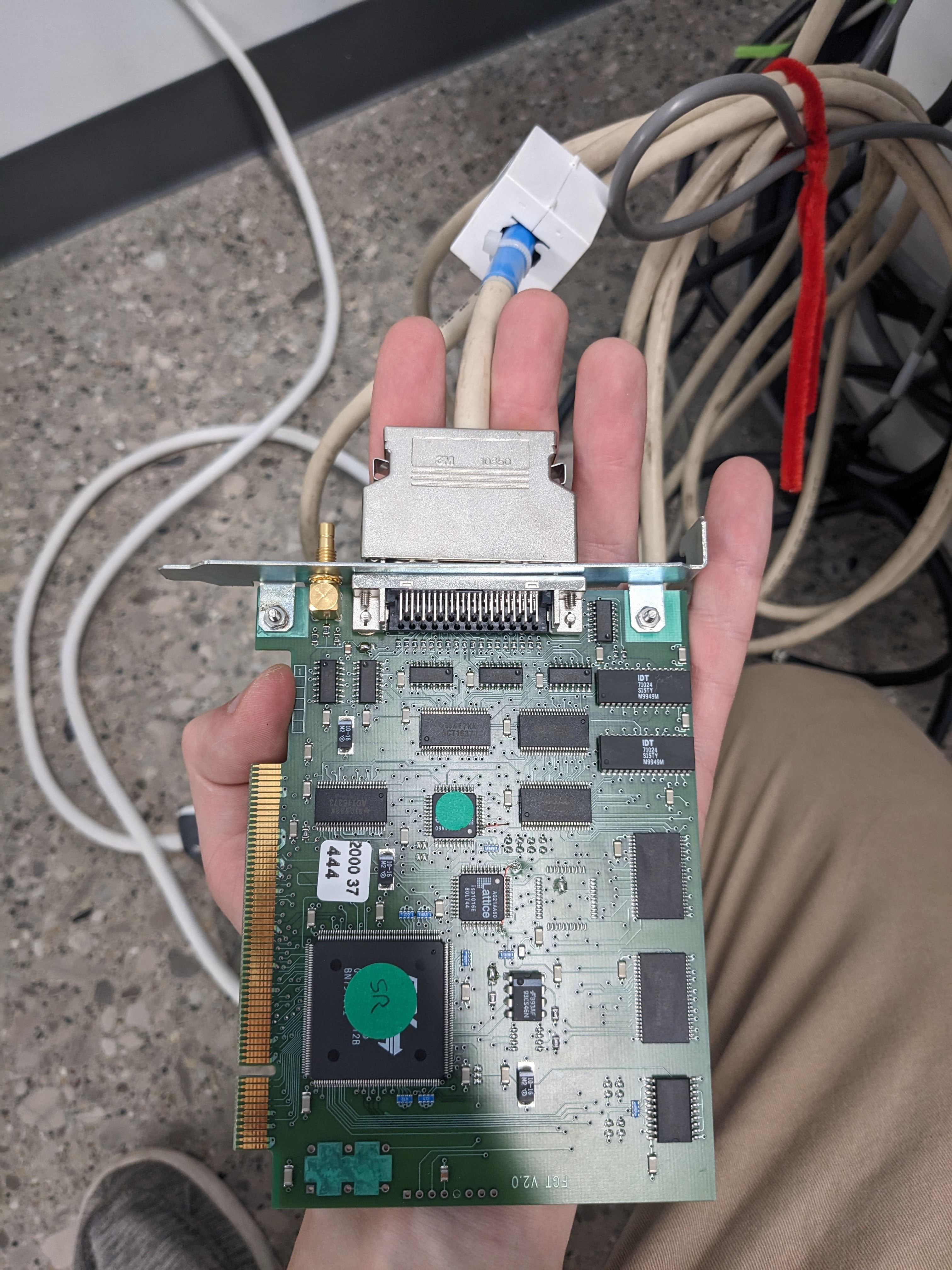
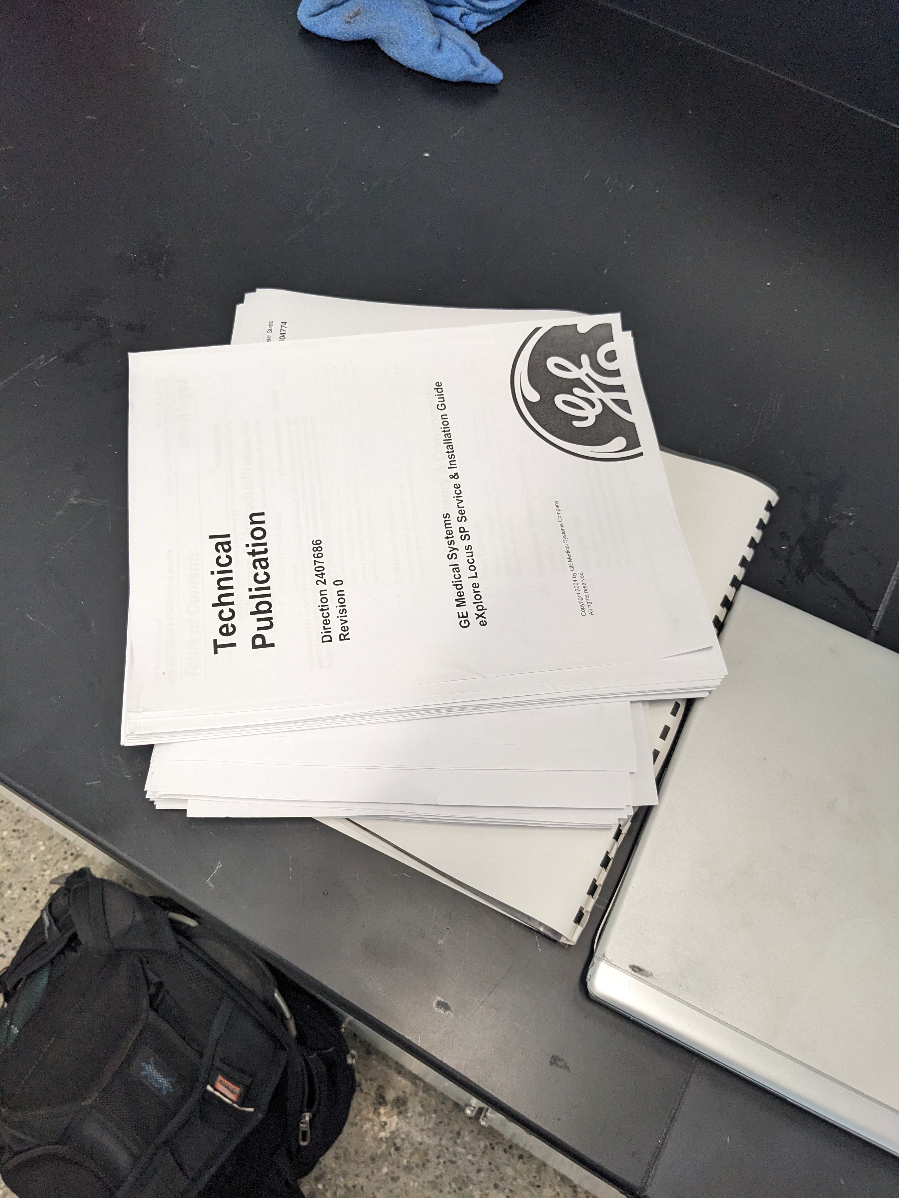
08/16/2023 at 02:24 • 0 commentsIt started with the arrival of the rare and mythical, ancient ATMEL LVDS capture card that fit the custom 50 pin connector to the camera. Thanks, Trifoil, for sending a spare!
![]()
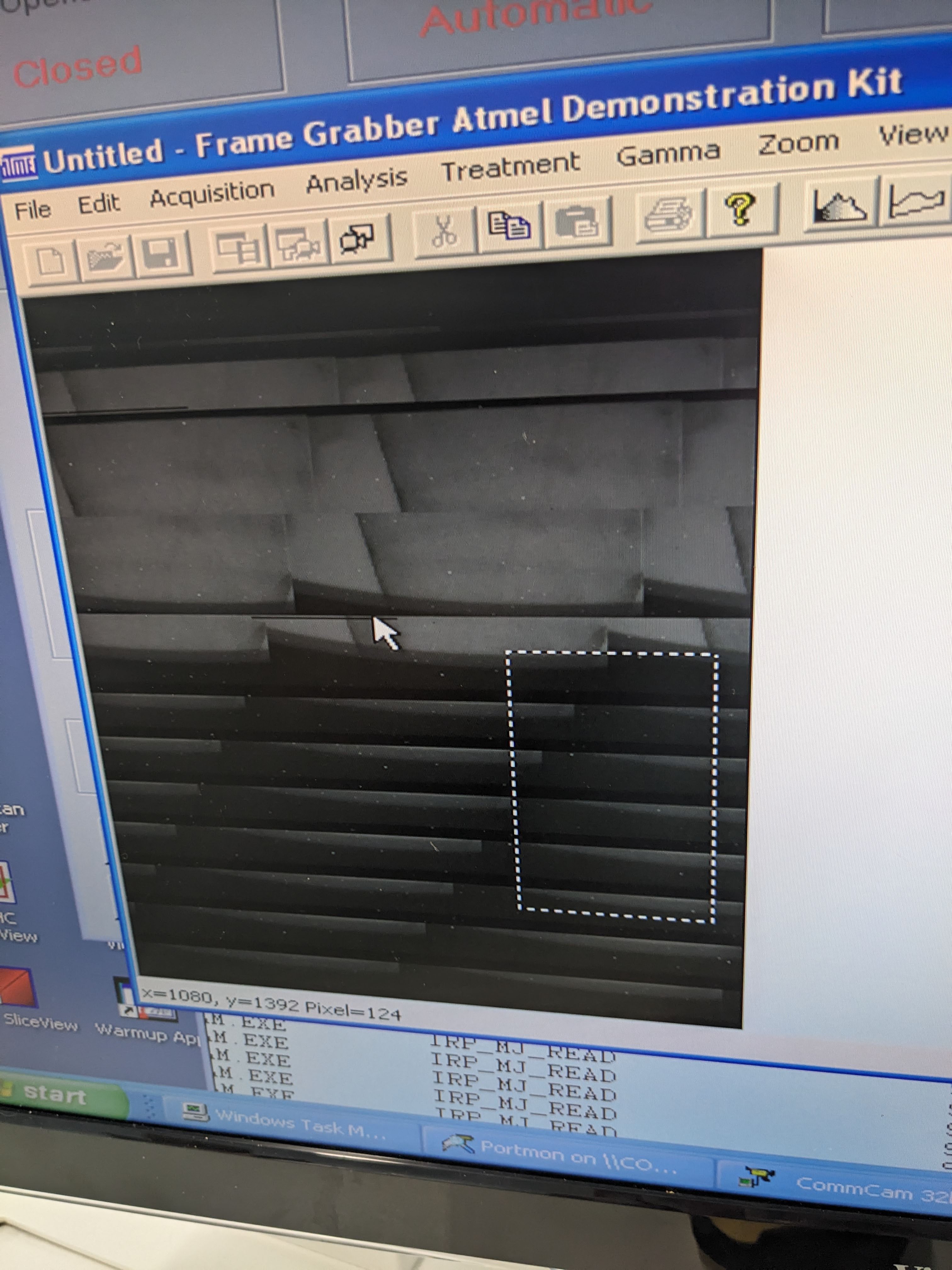
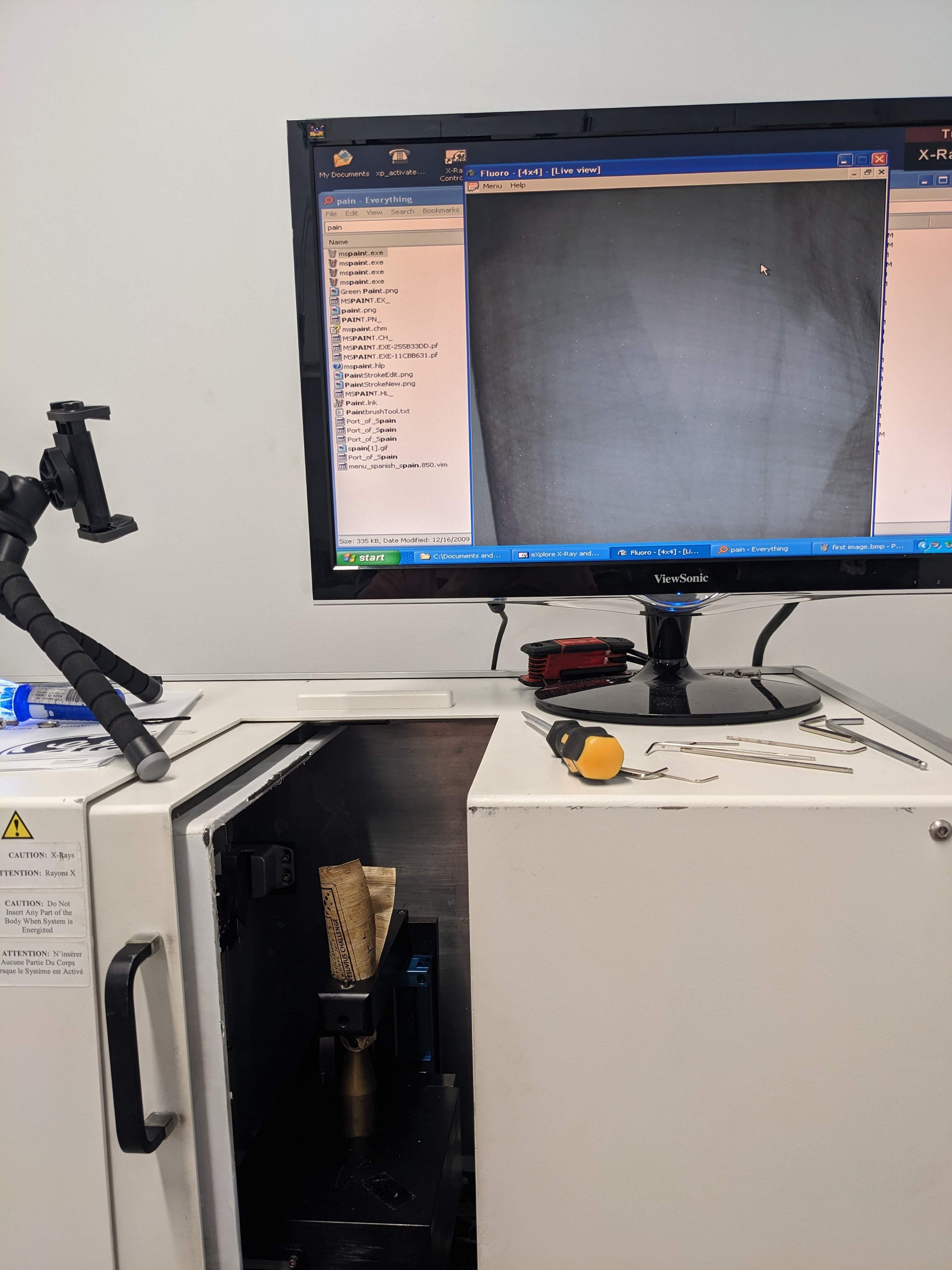
After installing, I was able to open up both Comcamm (for sending serial commands to the camera) and the FGT frame grabber program (for actually reading the images. Try as I might, though, all I got were blank images and occasionally something seriously buggy.
![]()
I was hoping I could set it to continuous readout mode and get some images, but apparently this very old CMOS sensor is unable to read out data while receiving new signal --- and the source is not capable of ramping on and off that quickly. In other words, there needs to be a shutter (in this case one that physically blocks x-rays) for it to work properly.![]()
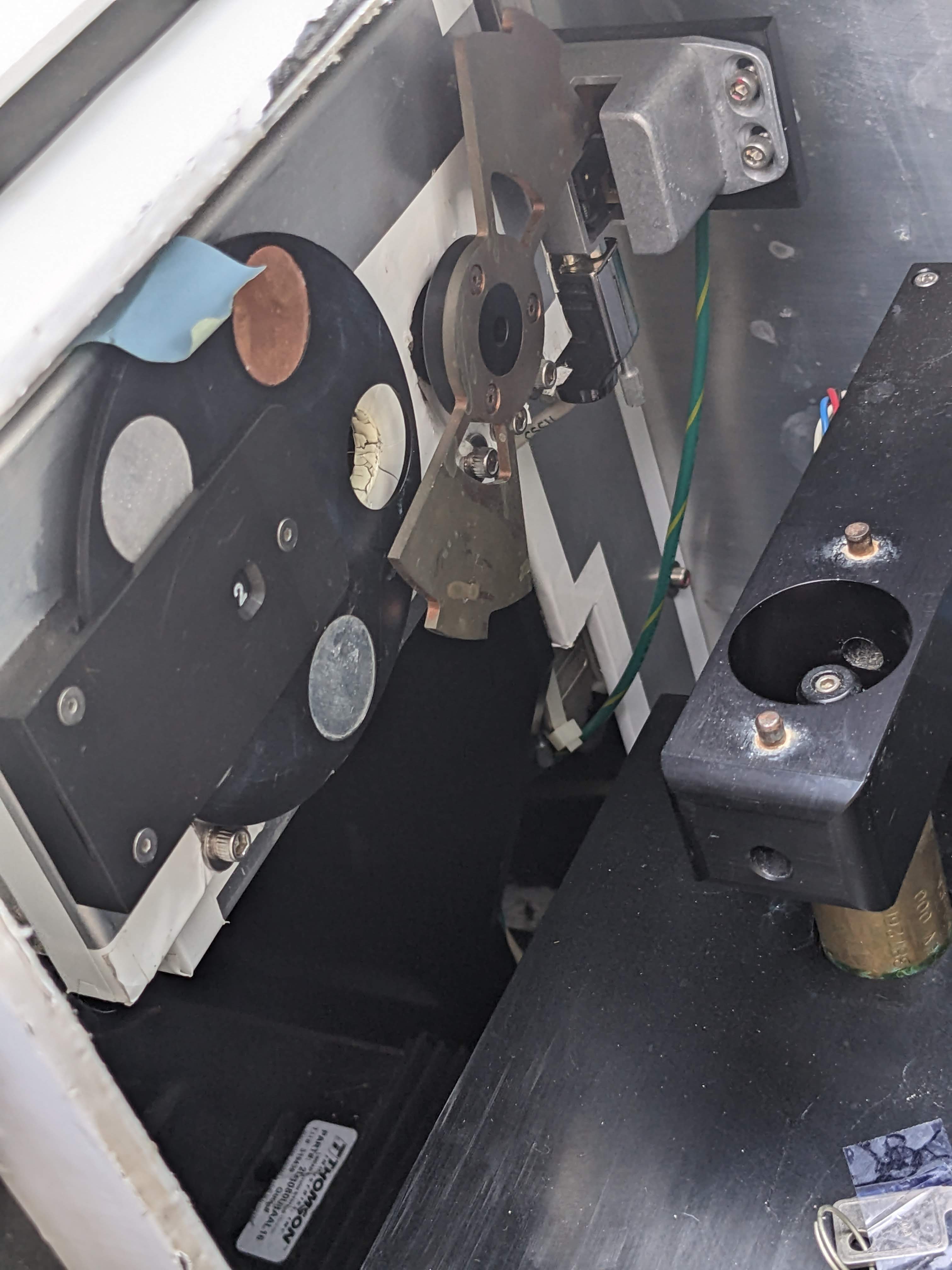
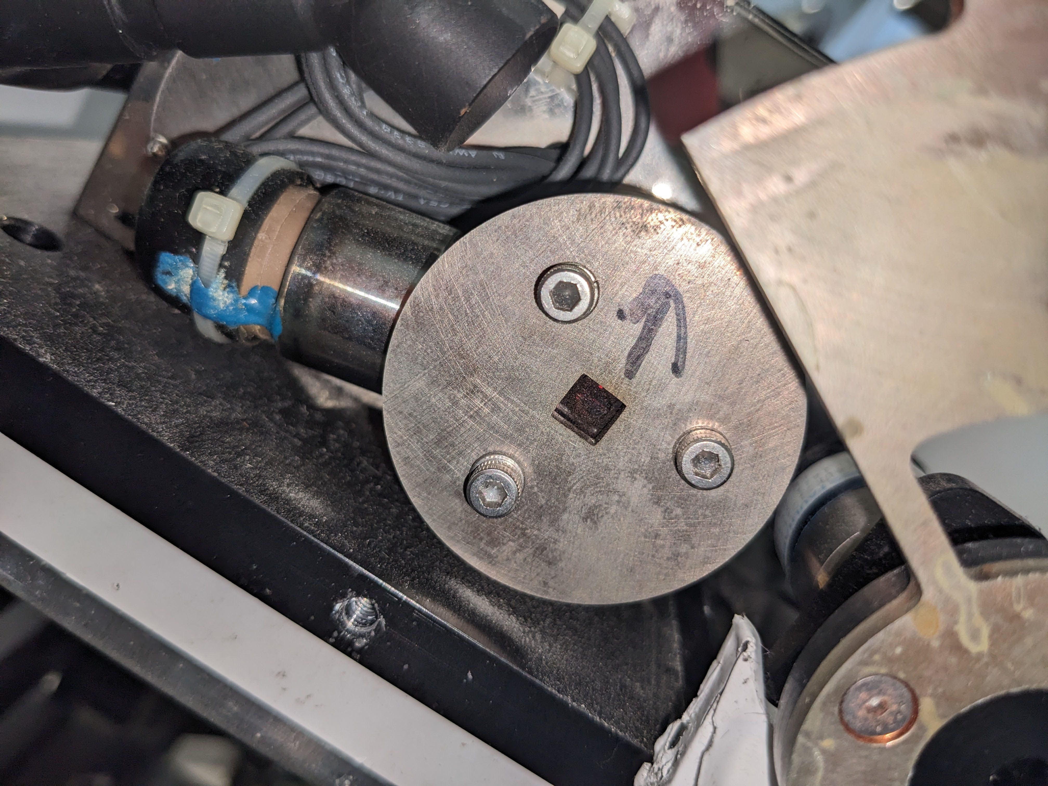
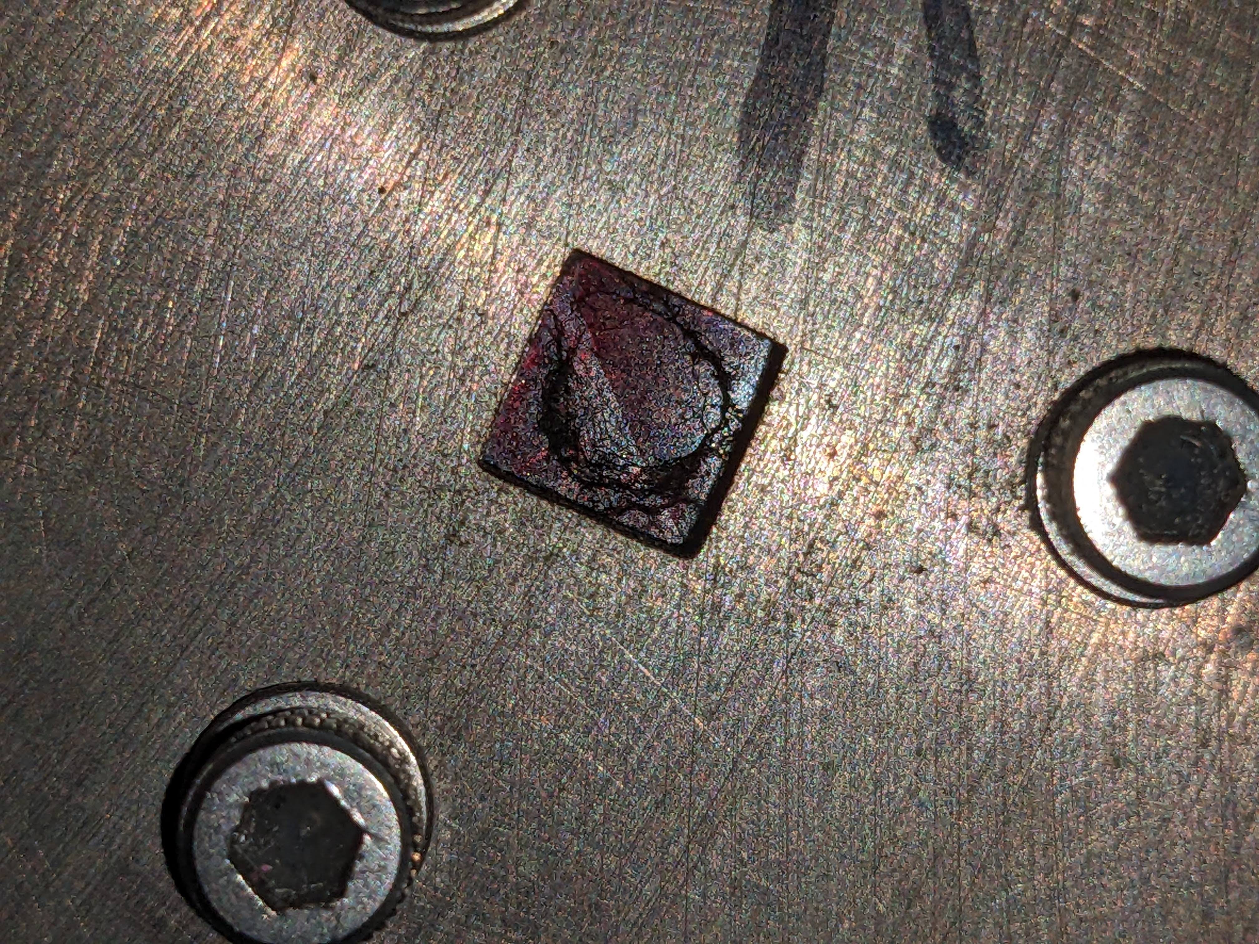
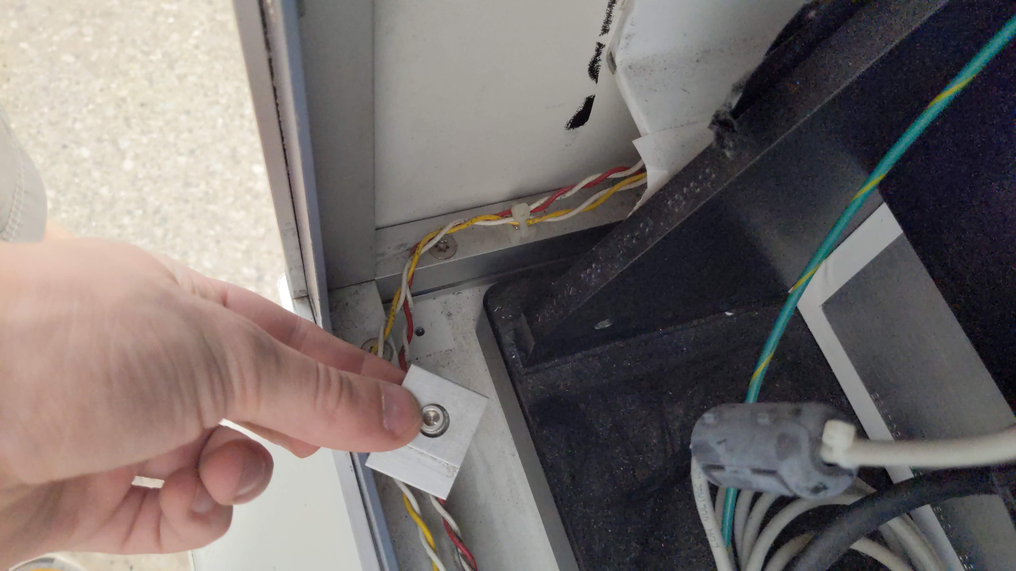
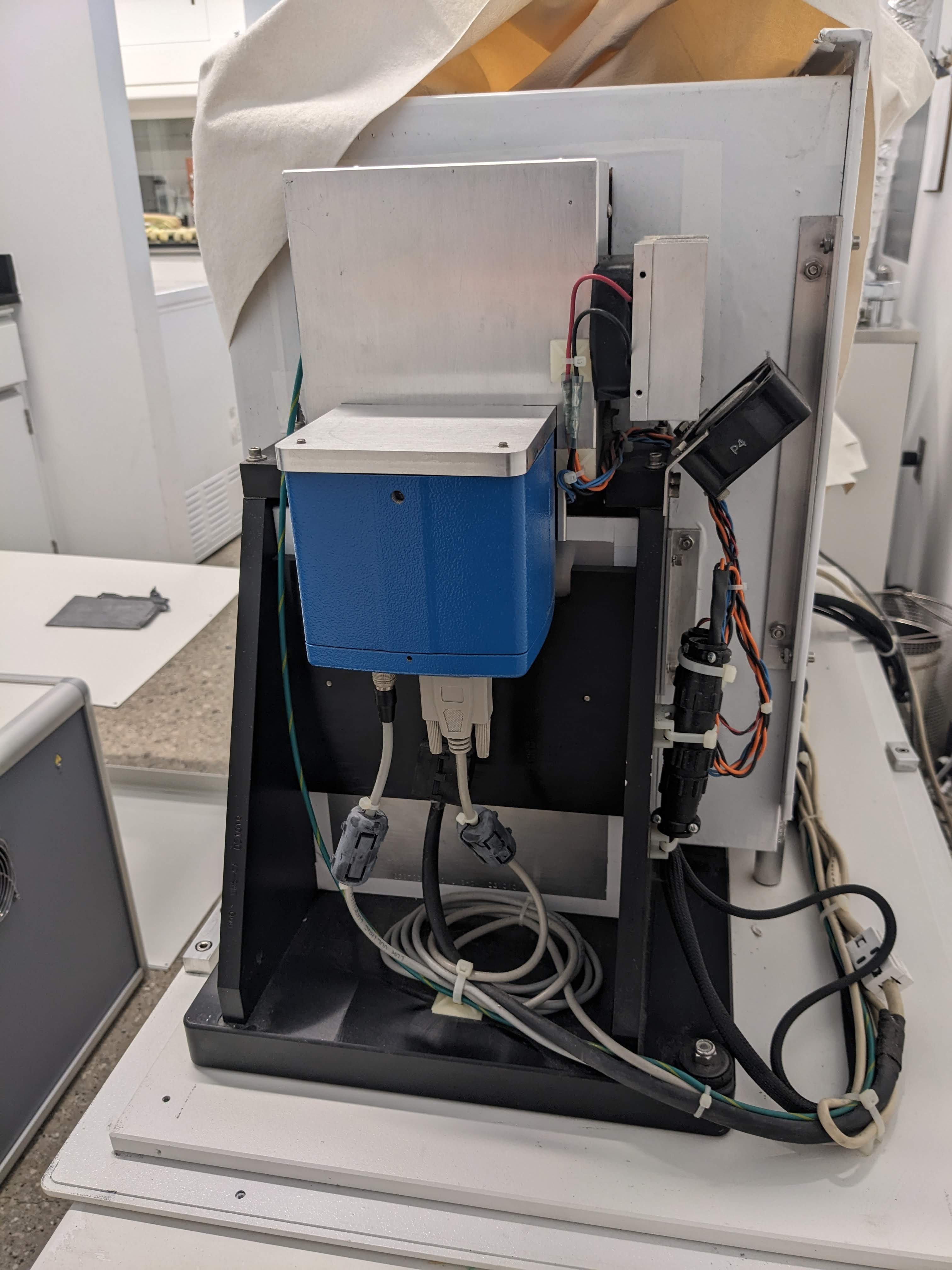
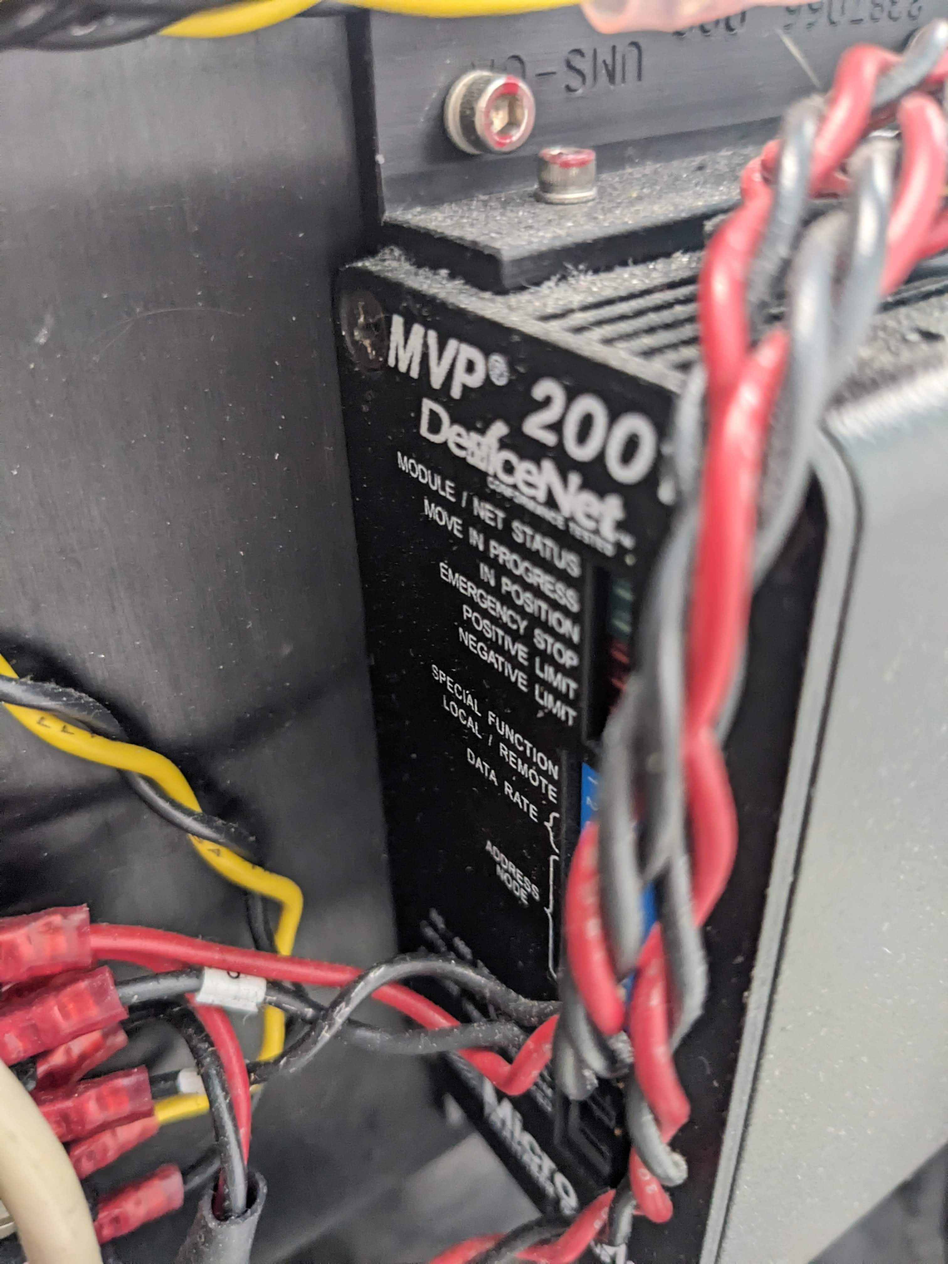
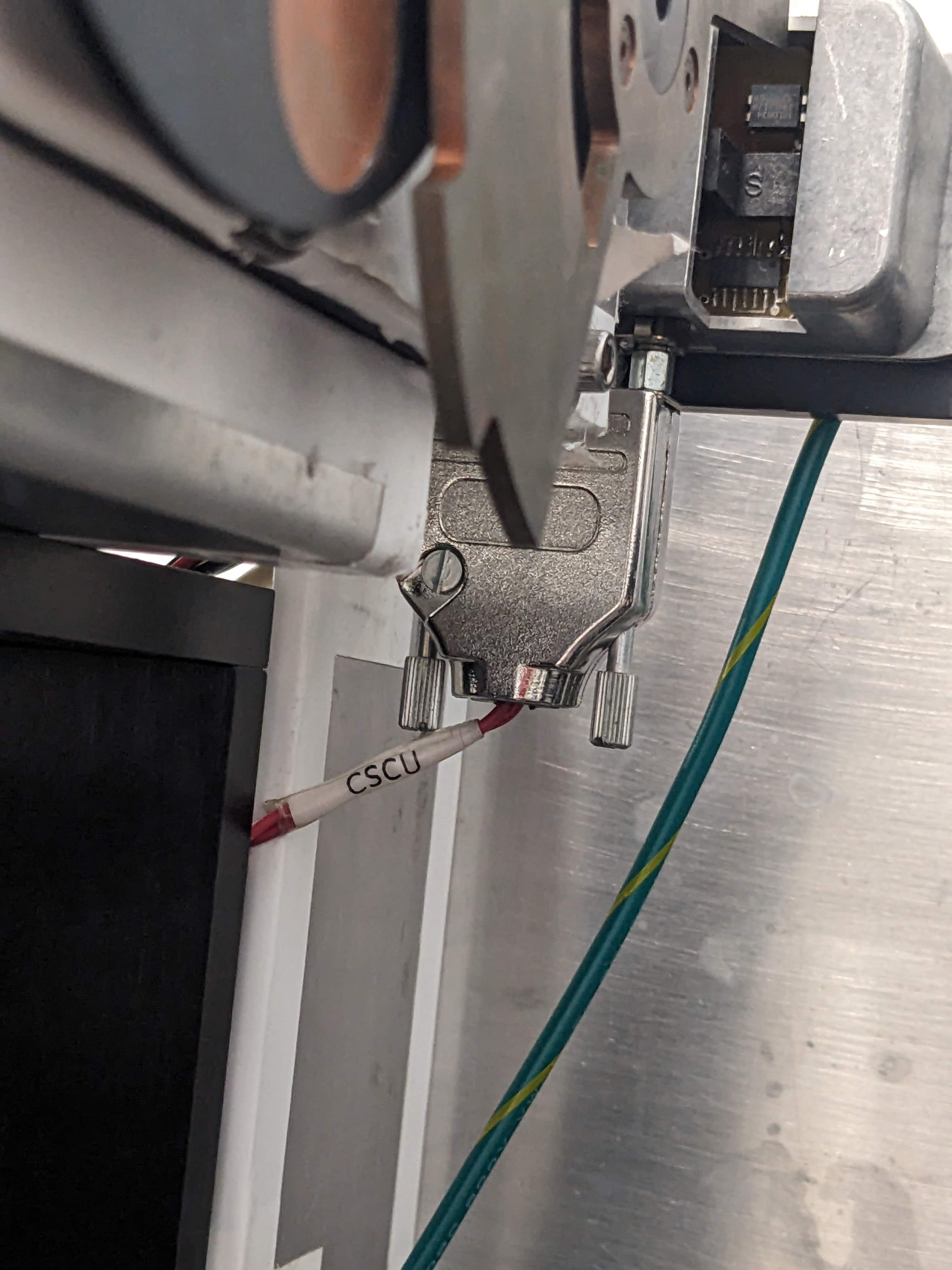
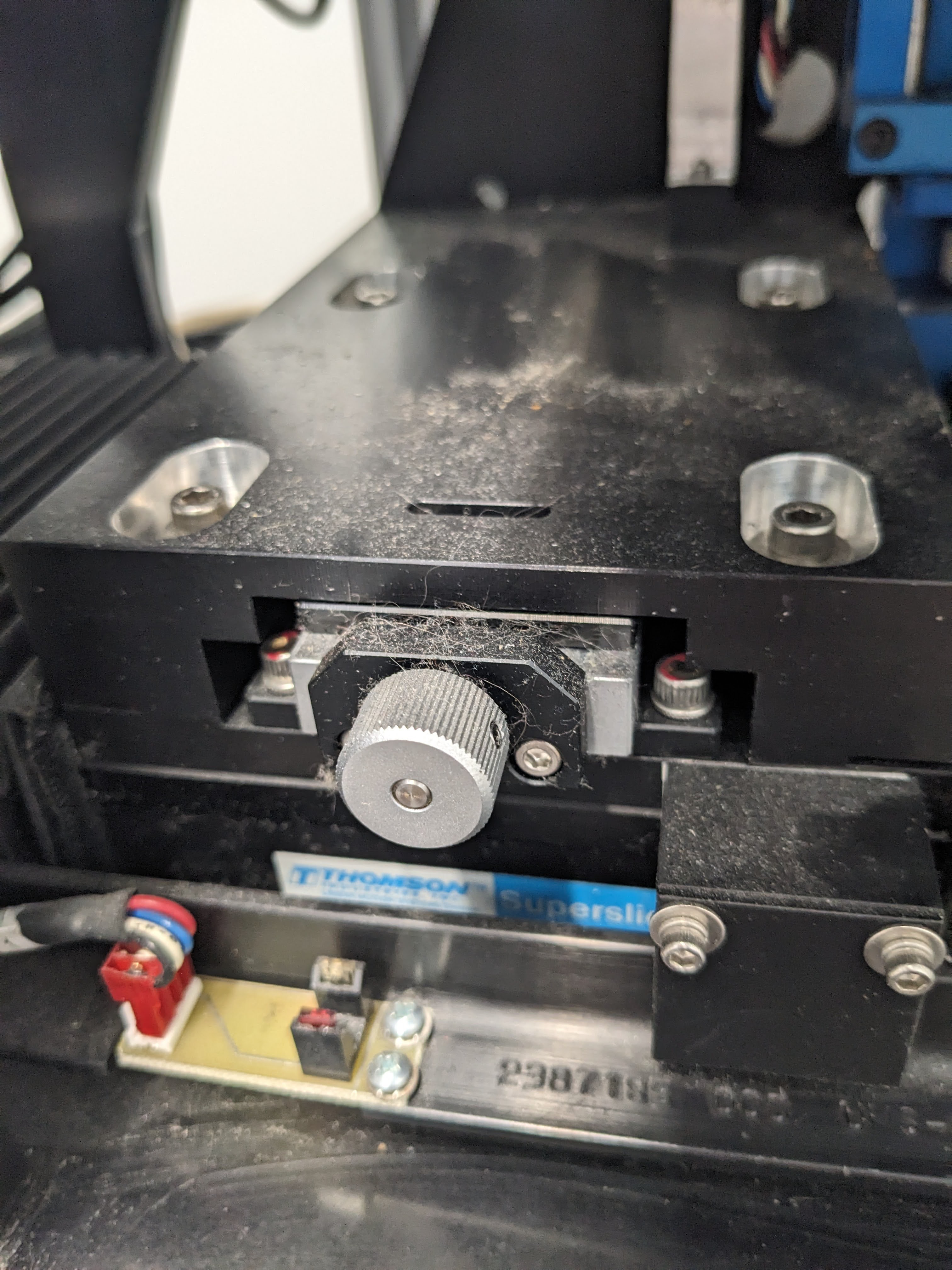
The shutter in this system is a block of 2mm thick sintered tungsten-copper (insider knowledge), attached to a geared, brushless DC motor, placed in between the source and the object and also passing through a little optical interrupt switch. The switch, motor, and control unit are then connected in a mess of wires back and forth to the camera, the machine control, and a direct connection to the computer that has never triggered. The shutter seems to be what the whole system is built around, almost --- like a little heart beat --- and nothing will work right if the shutter doesn't run.
![]()
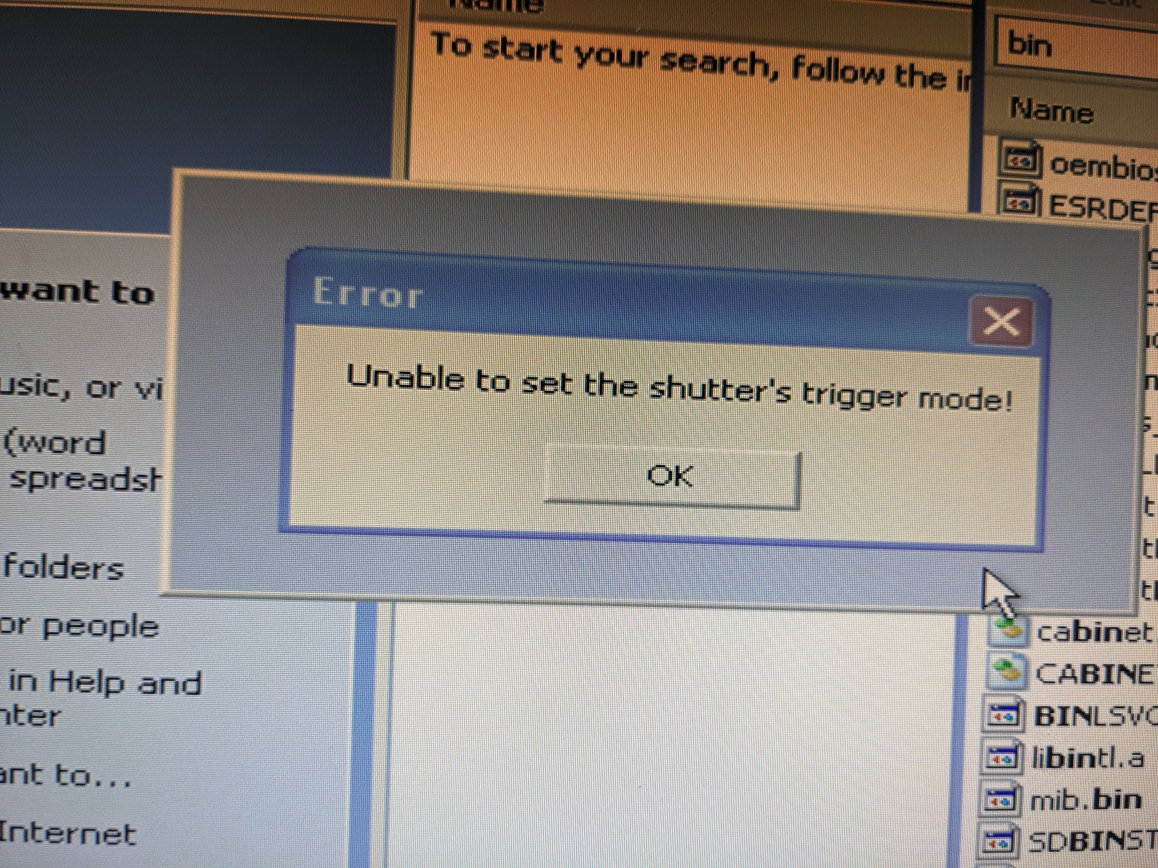
So you can imagine my frustration where, despite trying different cables, different ports, different rates, different operating systems, monitoring the ports, monitoring the program, and so many kinds of turn it off and on again, still getting some variation of the above error when starting the shutter controller. What else can I do? Corner the person who designed it 25 years ago?
Hmmm... there's an idea...
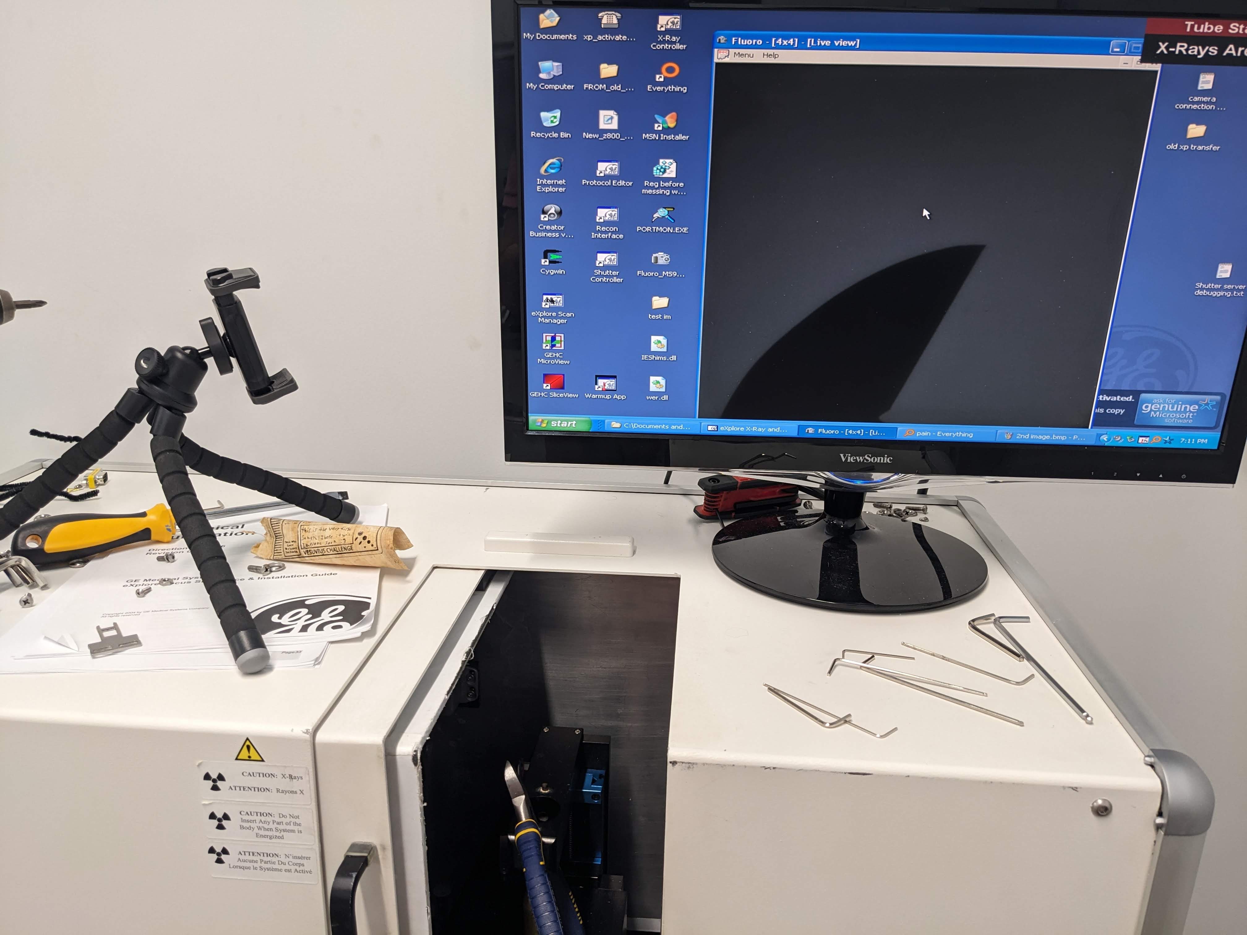
Anyway, there's also a native program called "Fluoro" for getting a live view of what the camera is seeing. Thankfully, it would open despite the shutter not initializing, and I was able to confirm that the camera is, in fact, communicating info with this program. By making the shutter rotate manually, I could get some images of "snow" (dark current) to pop up on the screen --- and the longer I'd let it "expose", the more snow there would be.
A great sign! Now... how to try with the x-rays?
In the long-term I can just drive that motor and its possible encoder with my own electronics. But in the short term --- that is, in the past few days --- I just wanted to get an image at all. Something to prove that the system works all together, that the scintillator hadn't peeled off or the cables hadn't run out of carburetor, or something.
Let's just say I found a way. So say hello to my first couple of proof-of-concept images.
![]()
![]()
That's some rolled-up papyrus (long story) and the blade of a random tool I had lying around. And I must say, I was surprised to see them look so good and sharp! I was expecting a terribly warped image or stripy lines that would normally be corrected for in a specific machine. But looking at these, this is functional for so many things right out of the gate --- and it'll only get better as I work my way through the calibration process.
But hey! I'd say I deserve a bit of a victory lap! About 10 straight weekends and a bunch of evenings, and of course, help from strangers and friends alike. We're getting there.
-
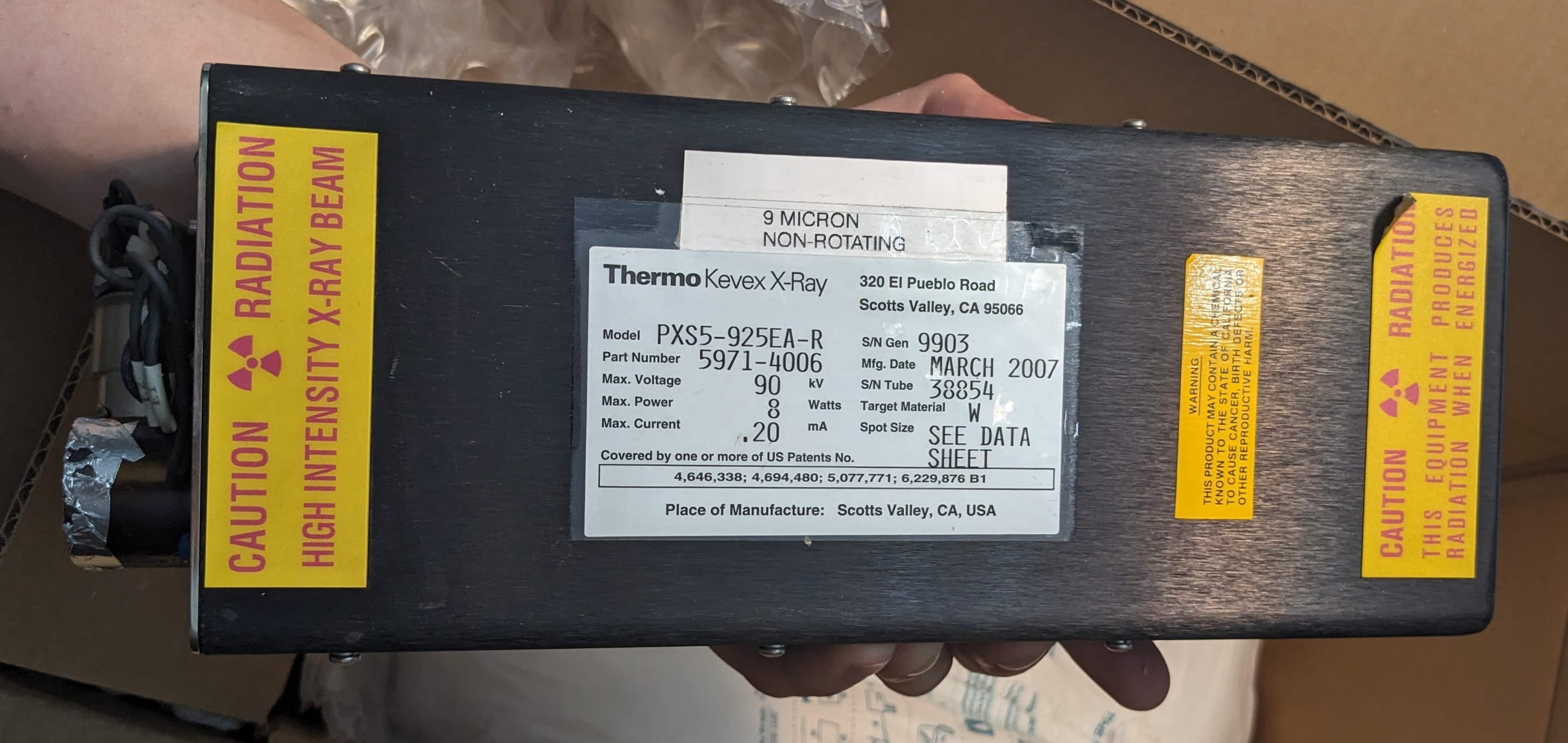
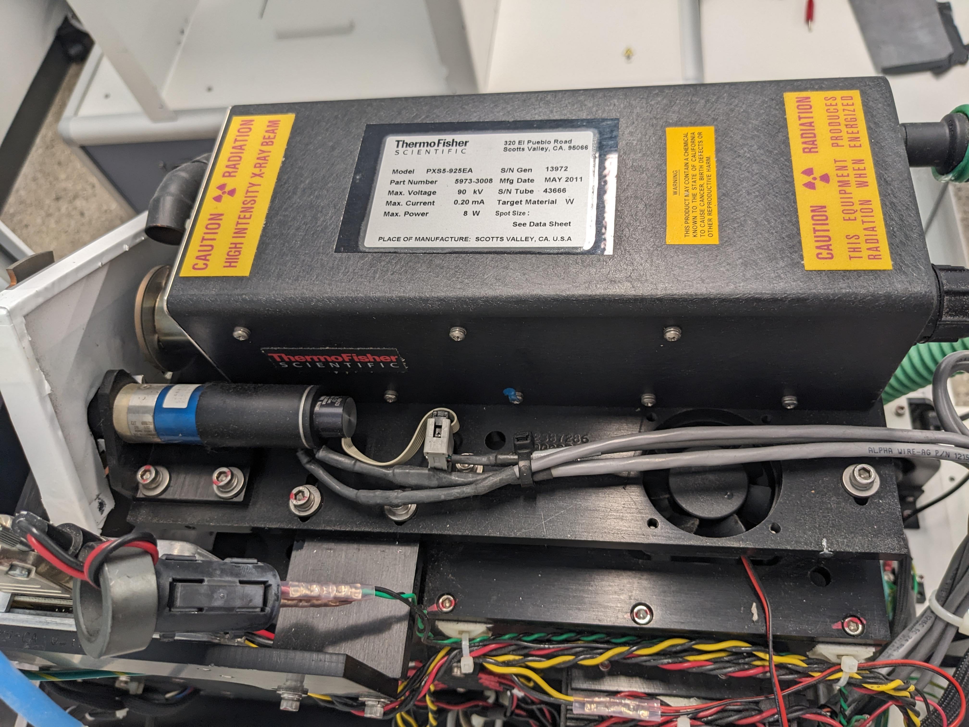
Datasheets for PXS5-925 KEVEX Thermo-electron Thermo-fisher SCIENTIFIC X-Ray Sources
08/12/2023 at 15:11 • 0 commentsThese datasheets were astonishingly difficult to get, and then all of a sudden they were here. They've been uploaded to the main files, again with as many keywords as I can muster to help any weary and lost souls that may follow.
Main takeaways:
- It's got oil
- 2 differences between EA and EA-RR variant are just the size of the spot (at half power: 9 microns, vs. 7 microns) and then the bigger spot size can nominally heat up slightly faster, which makes sense. Spot size is dependent on power and is bigger at 8 vs. 4 watts (so there must be focusing electronics) . The replacement is the one with the slightly bigger focal spot size, EA-RR.
- Can control with either potentiometer or external voltage, which I knew, but now I know exactly how. Sensing is just voltage too. A few volts.
- The cone of illumination is approximately 40 degrees.
- There are 2 signals: Stand-by to keep warm, and actual power. Do not turn off standby, while actual power is on!
- "not user servicable"
- Turn it up slowly
- Apparently some people can detect radiation by static tingle. Do not rely on this
- It shuts off at 120 percent set power
- If it arcs, that's bad, run the warmup again but more slowly
- Not focused/constant below 20 kv
- Don't run current below 5kv
- Rated for 45 kv 180 uamps, 90 kv at 90 uamps.
- above 70 kv is the especially careful zone. (So 60 seems like a safe middle ground)
So yeah! A lot of useful info. Still unknowns I'm curious about, like the actual contents of the tube, and especially potential servicability (maybe not in vacuum itself, but if there's arcing and it's out the tube...)
I'm back from oklahoma (with a sore throat) so this weekend will be trying the ancient LVDS capture card that just arrived. And seeing real 2D images --- possibly distorted, but hopefully nothing too serious. Assuming I can get the camera to connect at all! -
We Have X-Rays
08/06/2023 at 01:32 • 0 commentsWatch as much as you want, but a few minutes into a 13-minute conditioning process, we got x-rays. And a much higher voltage than I was planning to reach for a while. 88 kV! 20 or so microamps! That's more than a watt!
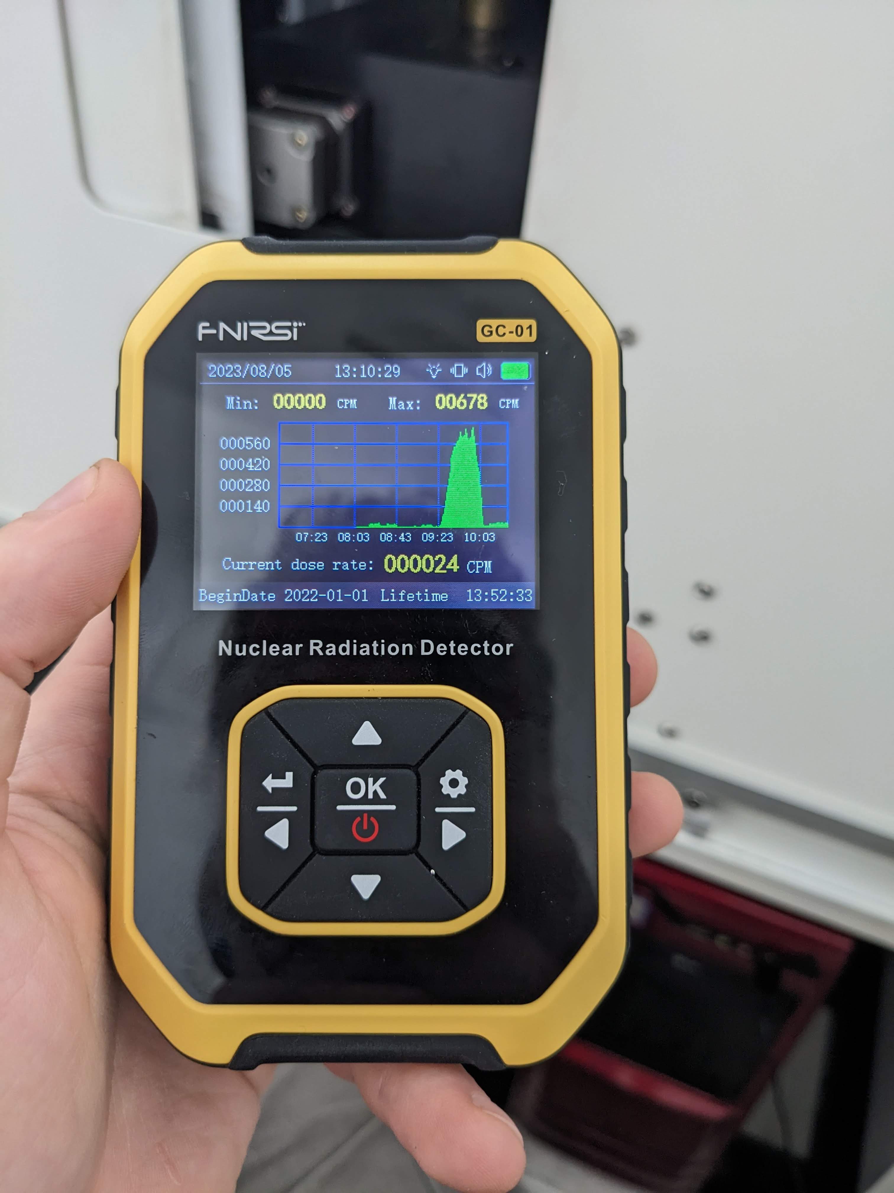
Also, I put my handy dandy graphical radiation detector inside the machine directly in the path of the beam. First I did 40 kv, but not microamps, and was surprised to see 600 counts per minute.
![]()
This is about 10 times background --- the same level as if you place it on an old thorium gas mantle.
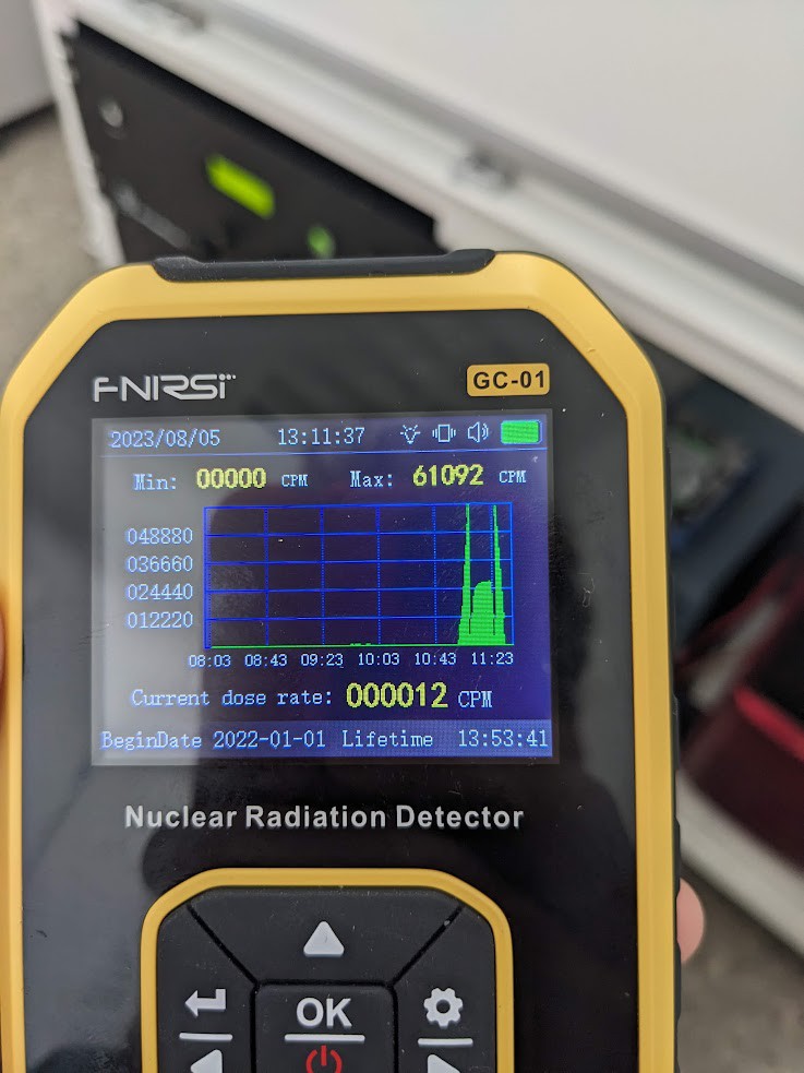
Then I tried it with 10 (9) microamps of current. In other words, we are at slightly less than half a watt of power, about 1% of which is actually x-rays.
![]()
Now THOSE are x-rays. You definitely don't want to be putting anything in your body directly in the path of this beam. It is not an incredibly huge total amount of x-rays compared to medical imaging. But it is very concentrated for something directly in the path of the beam.
Just a wild theory, but I wonder if the x-ray counts when no current switched could be used as a proxy for how rarefied the tube is --- in other words, is this leakage current through gunk and stuff in the tube? Or alternatively, is this the cathode filament staying at a "maintenance" temperature --- just not hot enough to emit significant electrons, but it still does a little bit?
Anyway, woo hoo. Capture card comes this week, while I will be in oklahoma. Next weekend... Gosh willing, we might be able to take some images.
-
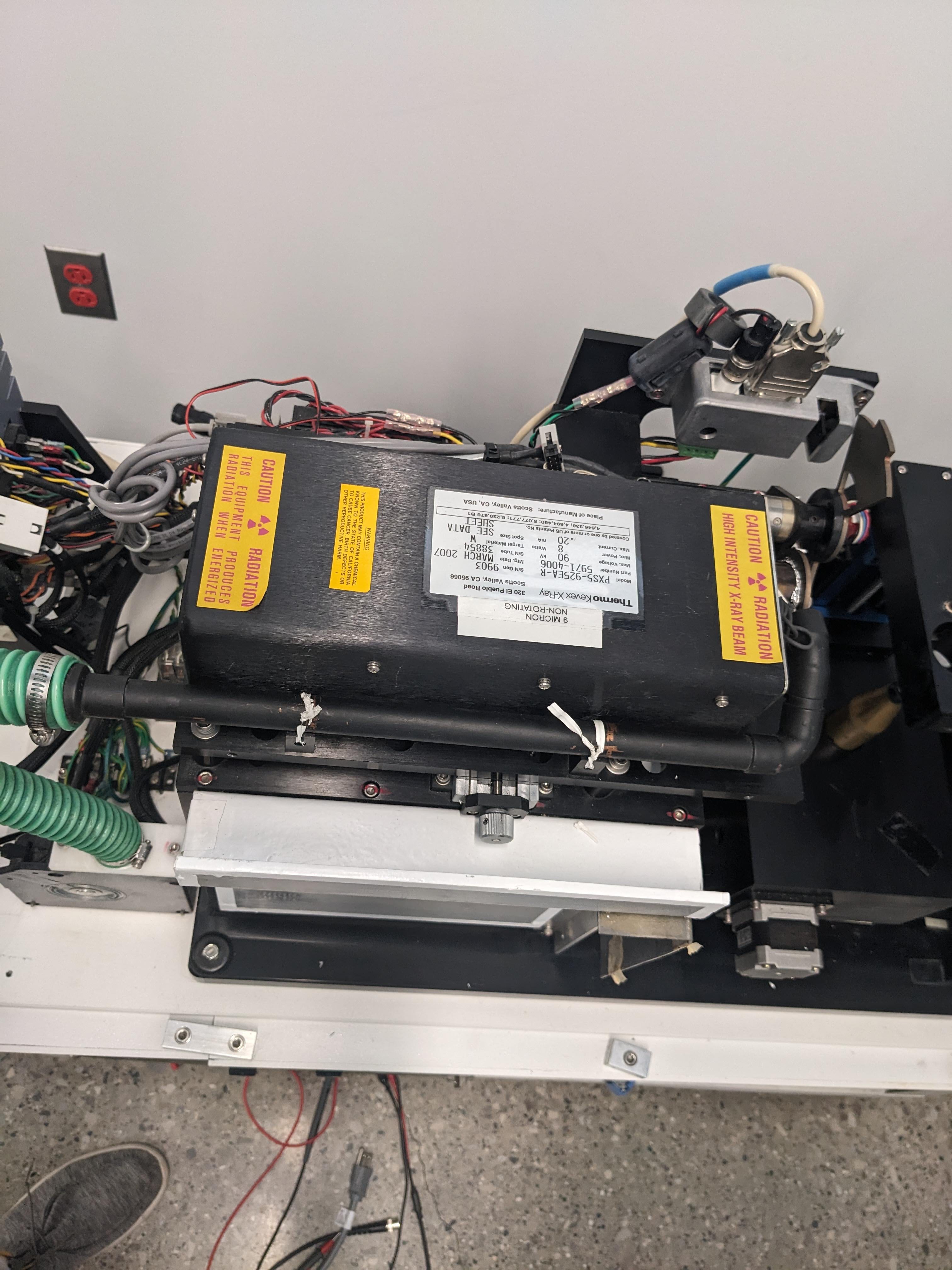
Changing the Source
08/05/2023 at 00:40 • 0 commentsThanks, Ebay! Thanks, Ebayer who gave me a good deal!
![]()
Is this thing from a video game or what?
![]()
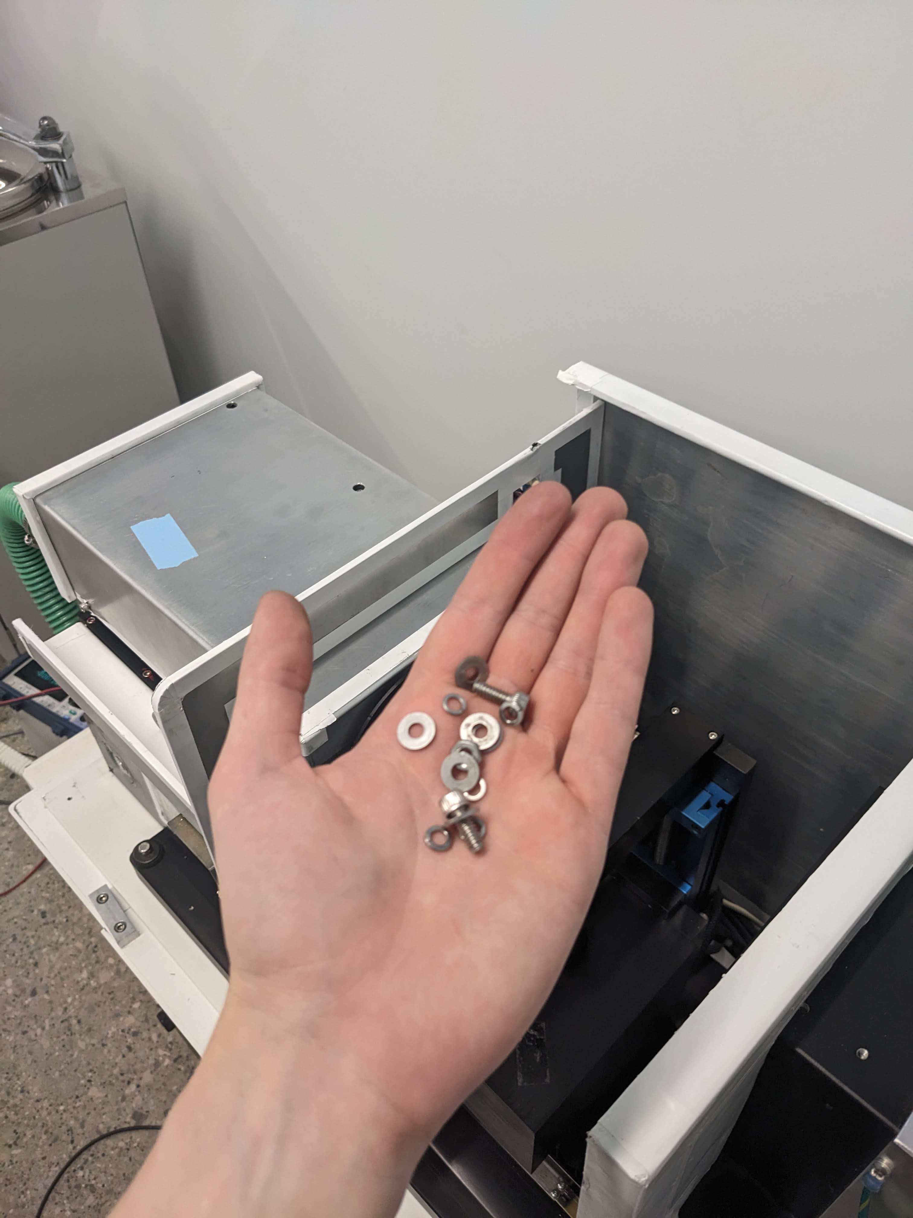
There are four large screws that hold the retaining block onto the main structure. This block holds the source and shutter motor, along with some electronics. Once that's loose, you have to unscrew the source itself from the underside, and there is also reference to "loosening and tightening the back screw ones from underneath" as opposed to tilting it and then taking it out.
![]()
So empty!
![]()
You can see on the old source that indeed, behind the collimator plate, the lexan window had all but disintegrated. Behind it is the intact beryllium window.
I didn't try to replace the lexan window, as i don't plan on touching the beryllium window. I did, however, try to cover the gap up between the source and the collimator window, as presumably the window would have also protected somewhat against dust or anything else in the air stream directly pointed at it.
![]()
Source back in place, I decided to just go ahead and put all the shielding back (rather than put the case on and test it, in case something was wrong). Along the way, I left many traces that it was an unprofessional who had to shim the shielding or use twisty ties instead of zip ties. Also, no screws made it back into the same location.
![]()
Finally, there was just the case left... and I looked around and it was the evening! Everyone had gone home! And you need 2 or 3 people to lug the case around! Gosh dangit to heck!
I really want to get the source tested before I go to oklahoma for work this week... -
Reaching The Source
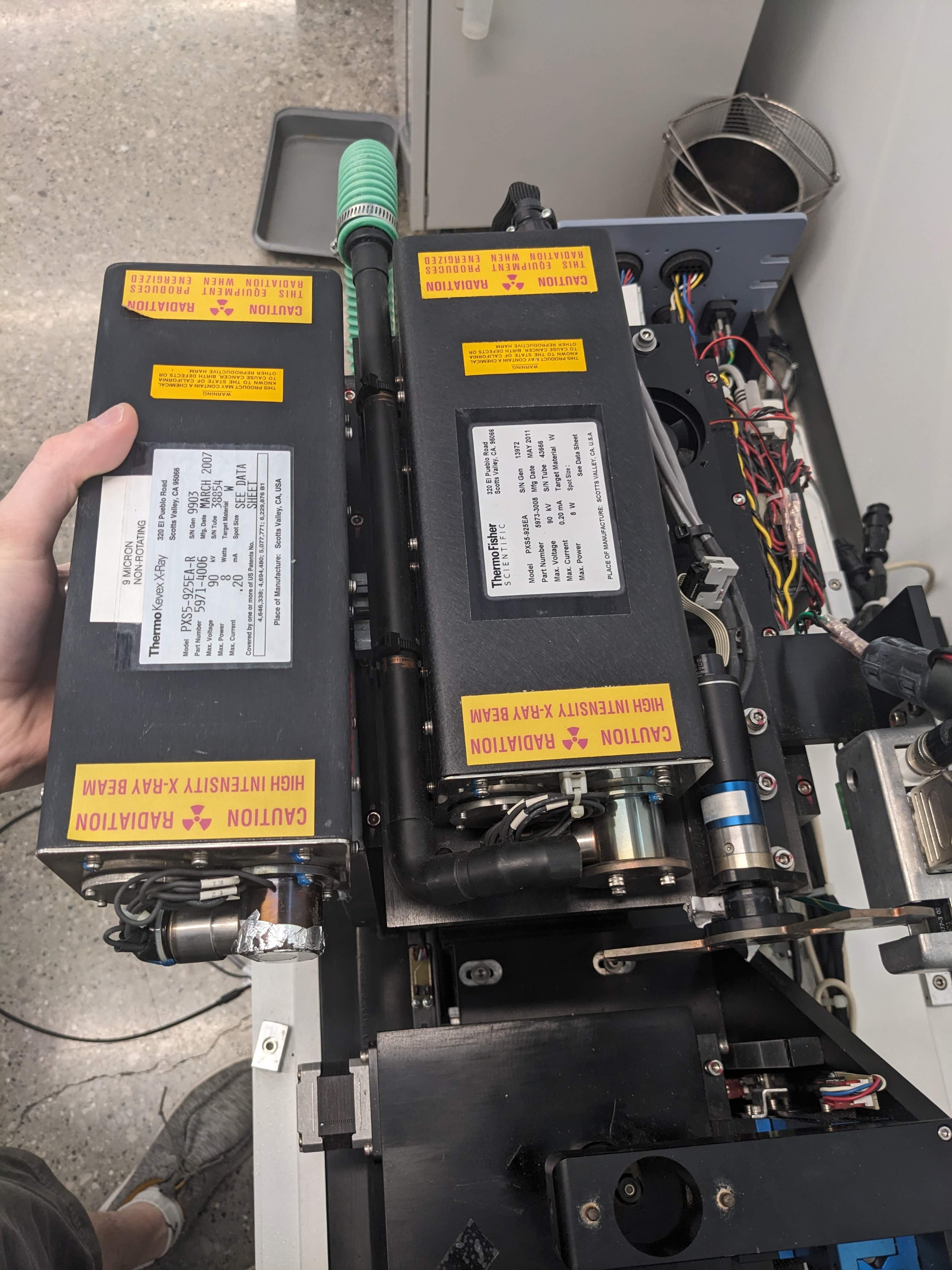
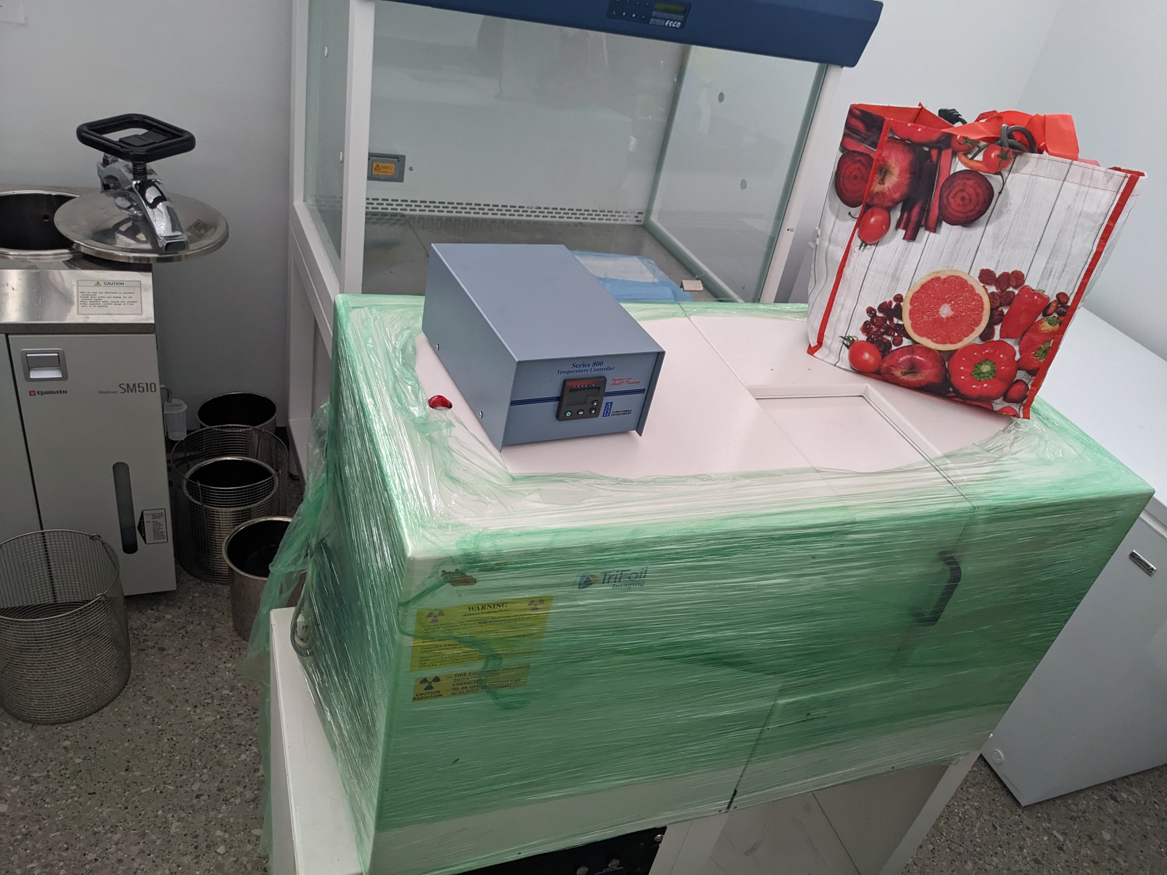
07/31/2023 at 00:04 • 0 commentsSo as a recap, first she was unwrapped:
![]()
Then it turned out there was an extra 2-part 'bonus' case:
![]()
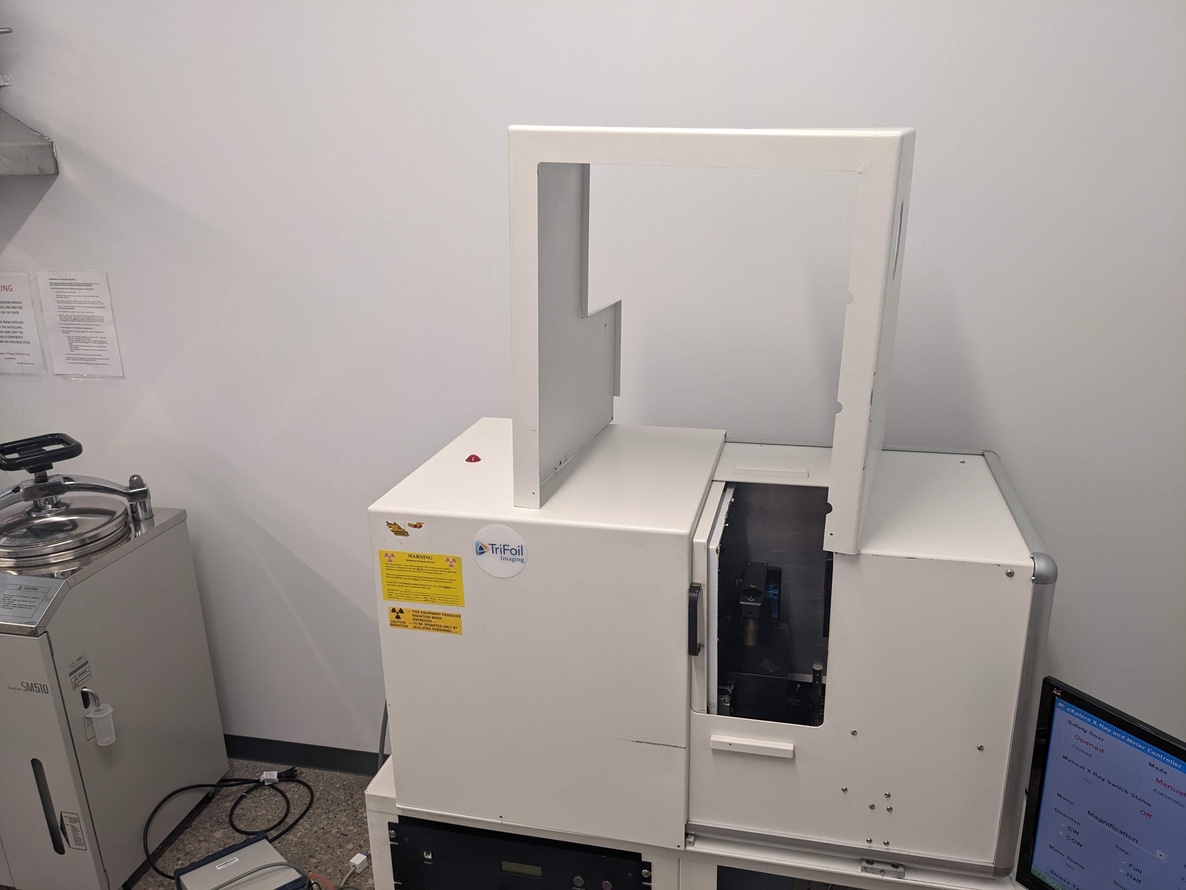
Underneath which was the handsome original case:
![]()
About 50 pounds of side panels and 100+ pounds of main case comes off:
![]()
And then, off comes 40 pound lead back shielding panel, lead left shielding panel, Filter wheel, lead source front shielding panel, lead source back shielding panel, and finally, the lead cover over the source.
And we get to the source.
![]()
Look how far we've come (and removed) from this machine. But here is it --- pretty much everything we've taken off, and the machine would still work. It would not be good for fragile human beings, but it would work. Everything that's left, though --- apart from another jillion little panels of lead shielding --- is essential.
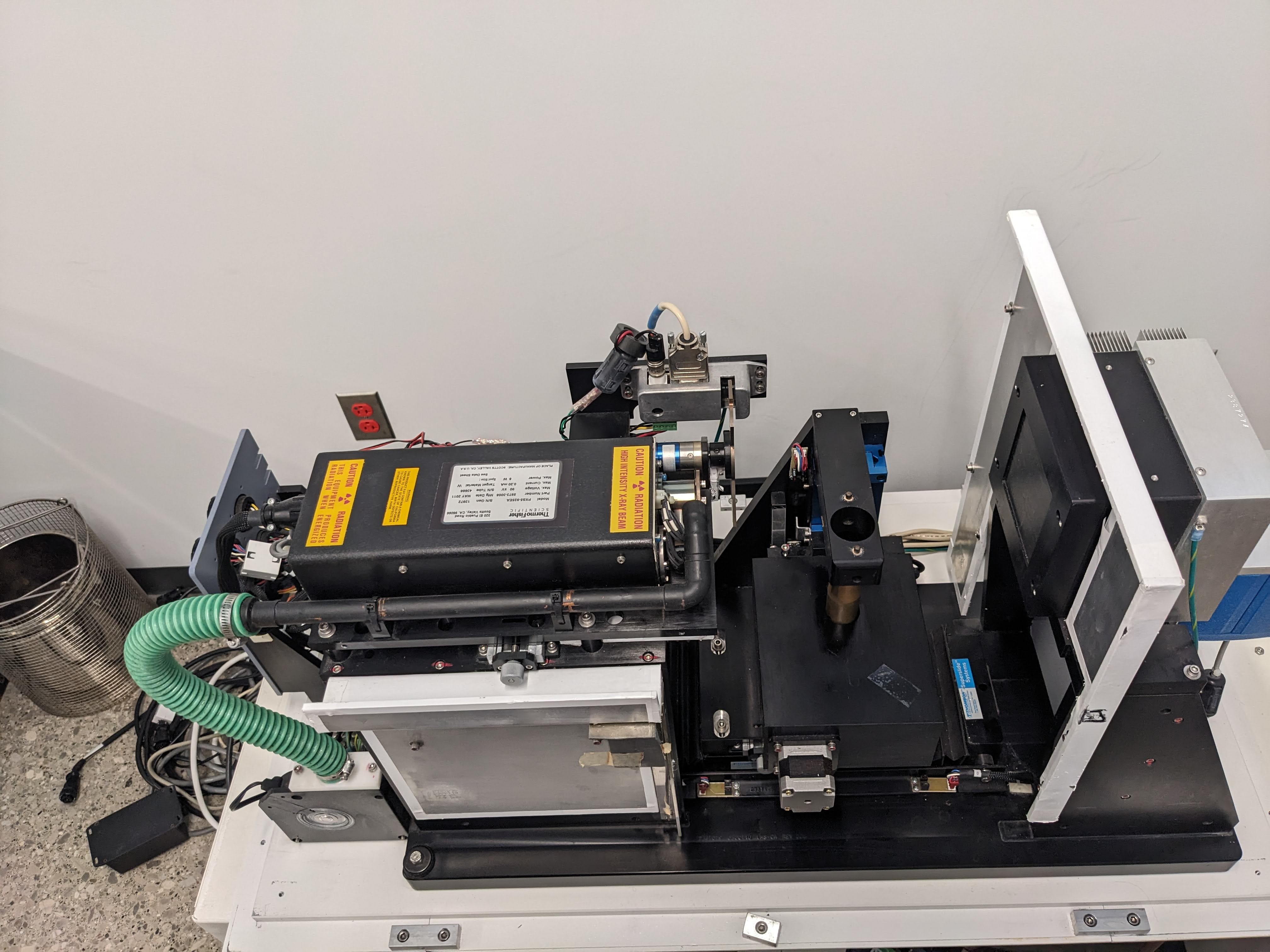
Especially the source.![]()
There she is, and what first surprised me was the manufactured 2011. That and confusion as it whether it is thermo-electron, thermo-kevex, or thermo-fisher scientific. I may honestly just go visit that address the next time I am in the area, and find out for myself.
Something weird is the cooling pipe, which faces at the general vicinity of the output and not (as I would expect) fit into some kind of opening on the source shell.![]()
Maybe it's fine...
What's definitely not fine is, peering into the collimator plate, it looks like something is totally fried:![]()
![]()
My best guess is that, in between the beryllium tube envelope and the metal collimator plate, the 'lexan window' (as service manual says) has been fried. Somewhere else is a field service upgrade that instructs to remove the window, so maybe it was identified as a cause of concern. Regardless, that is not likely to be the cause of the arcing.And in any case, a working one will soon take its place.
-
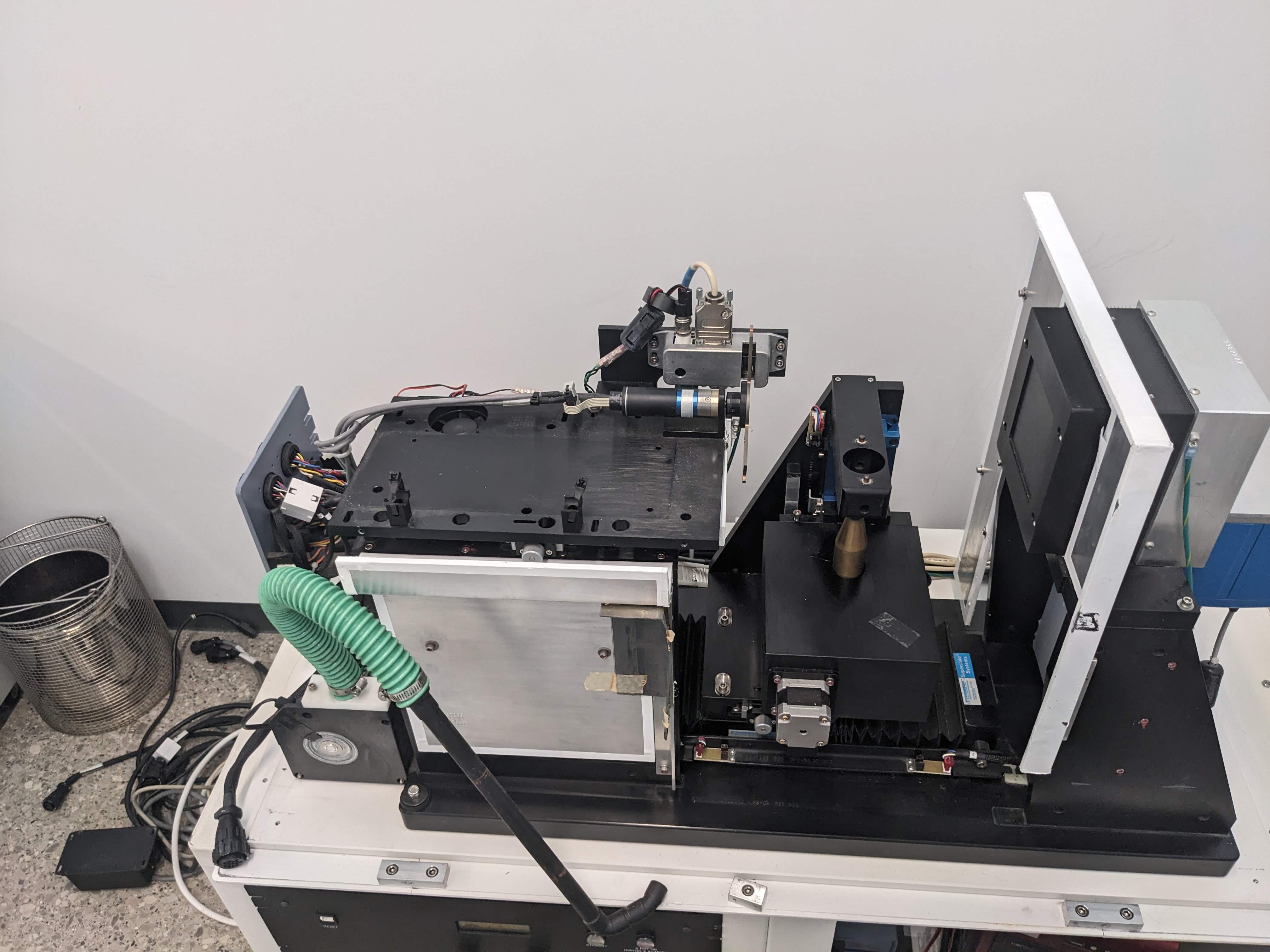
The Case Comes Off
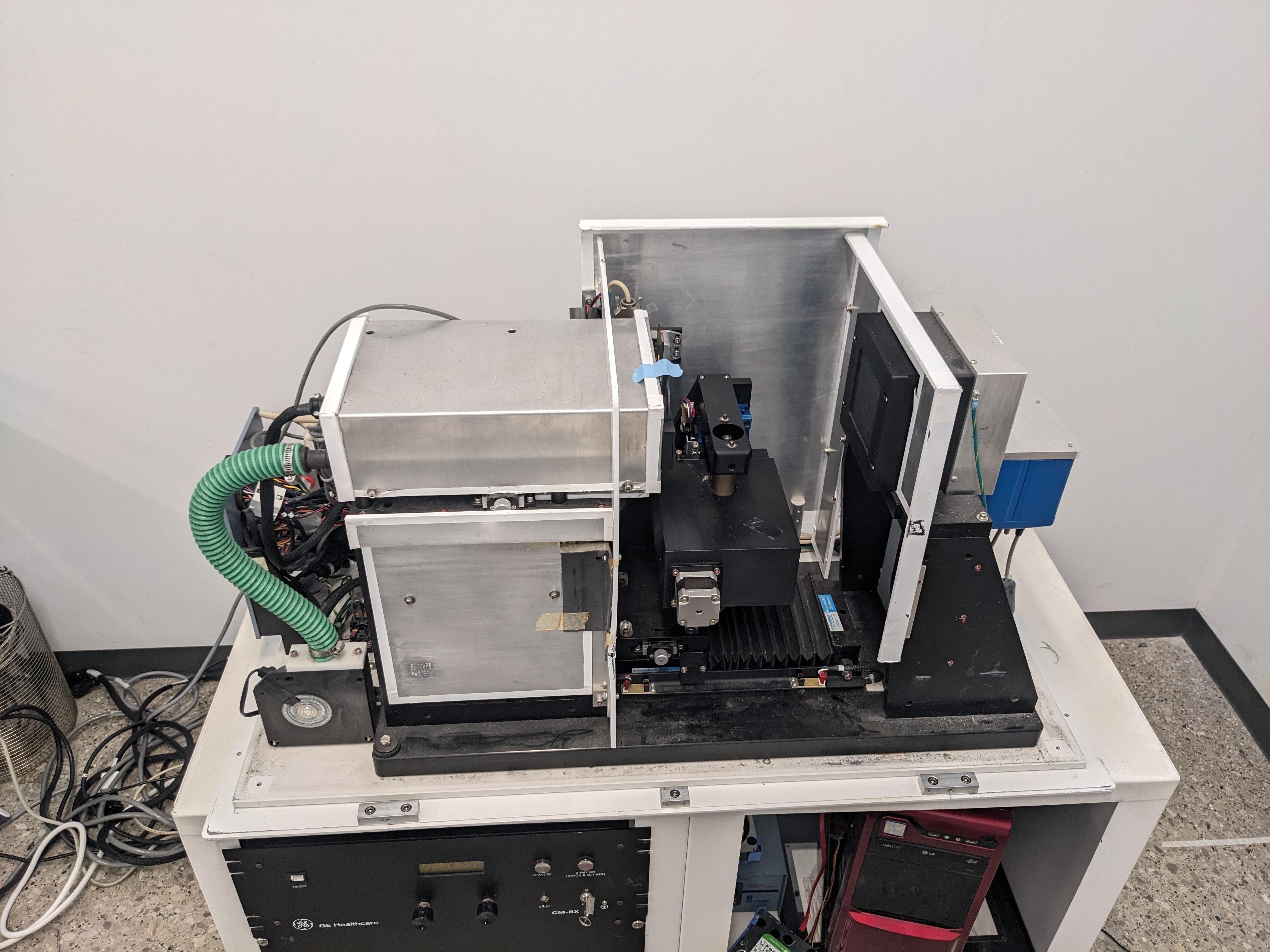
07/23/2023 at 23:27 • 0 commentsTaking off the case was hard because the case is heavy. "two or three people are needed to safely lift it out of the way", the service manual says. It was definitely three people. You need to remove four bolts and some cabling, and then it can be slid and lifted out of the way of the internals.
![]()
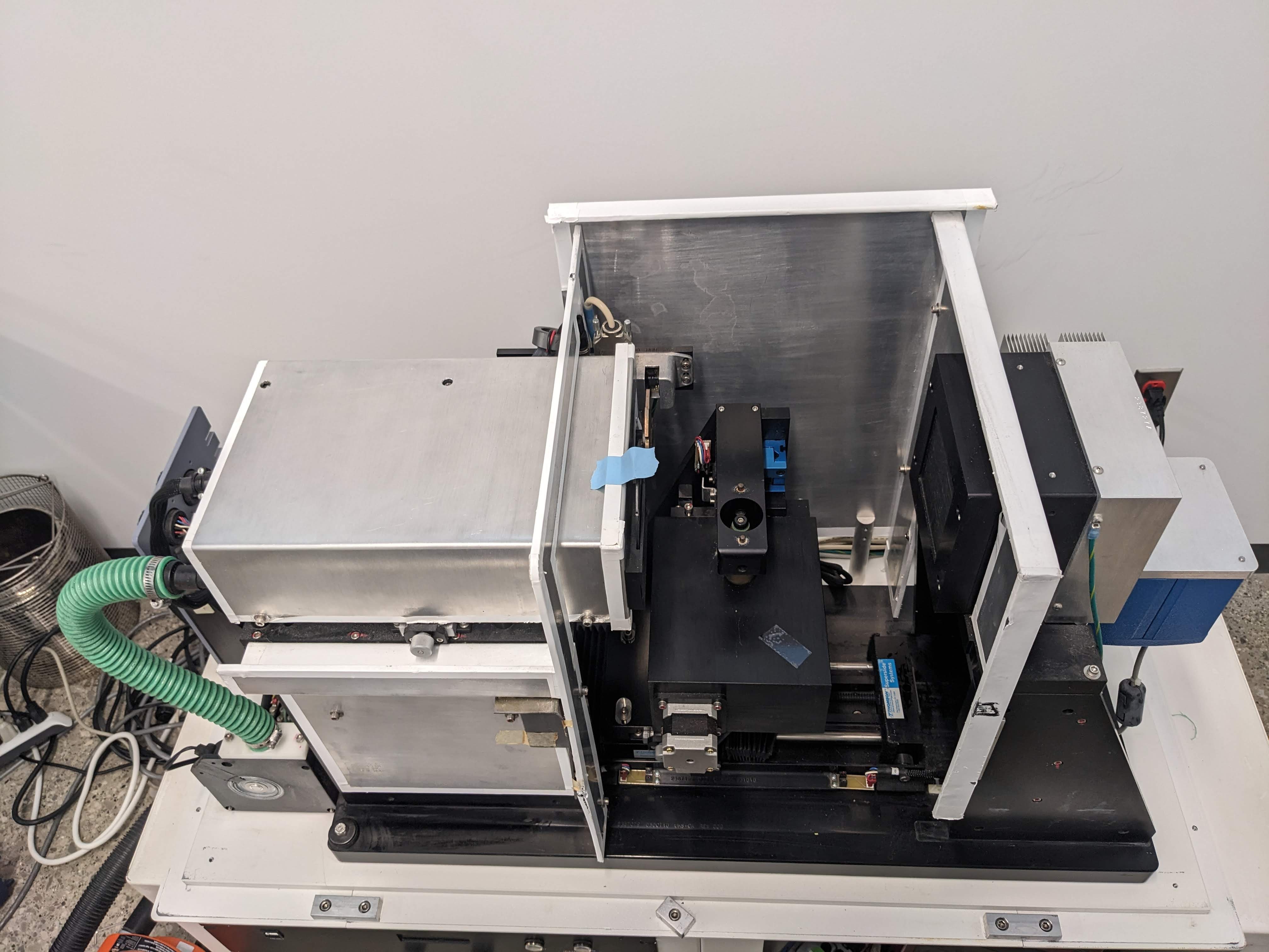
And here she is, after a bit of a vacuum and wipedown with a wet shammy:
![]()
Source is on the left, motors are in the middle, detector is on the right. NBD. The vast majority of the screws and everything is for shielding. The right side is more heavily shielded and there were some misc. pieces of lead that were literally taped on to I guess weak spots. Some of them had fallen off. Not concerning at all --- or at least, not until my x-rays start to freaking work.
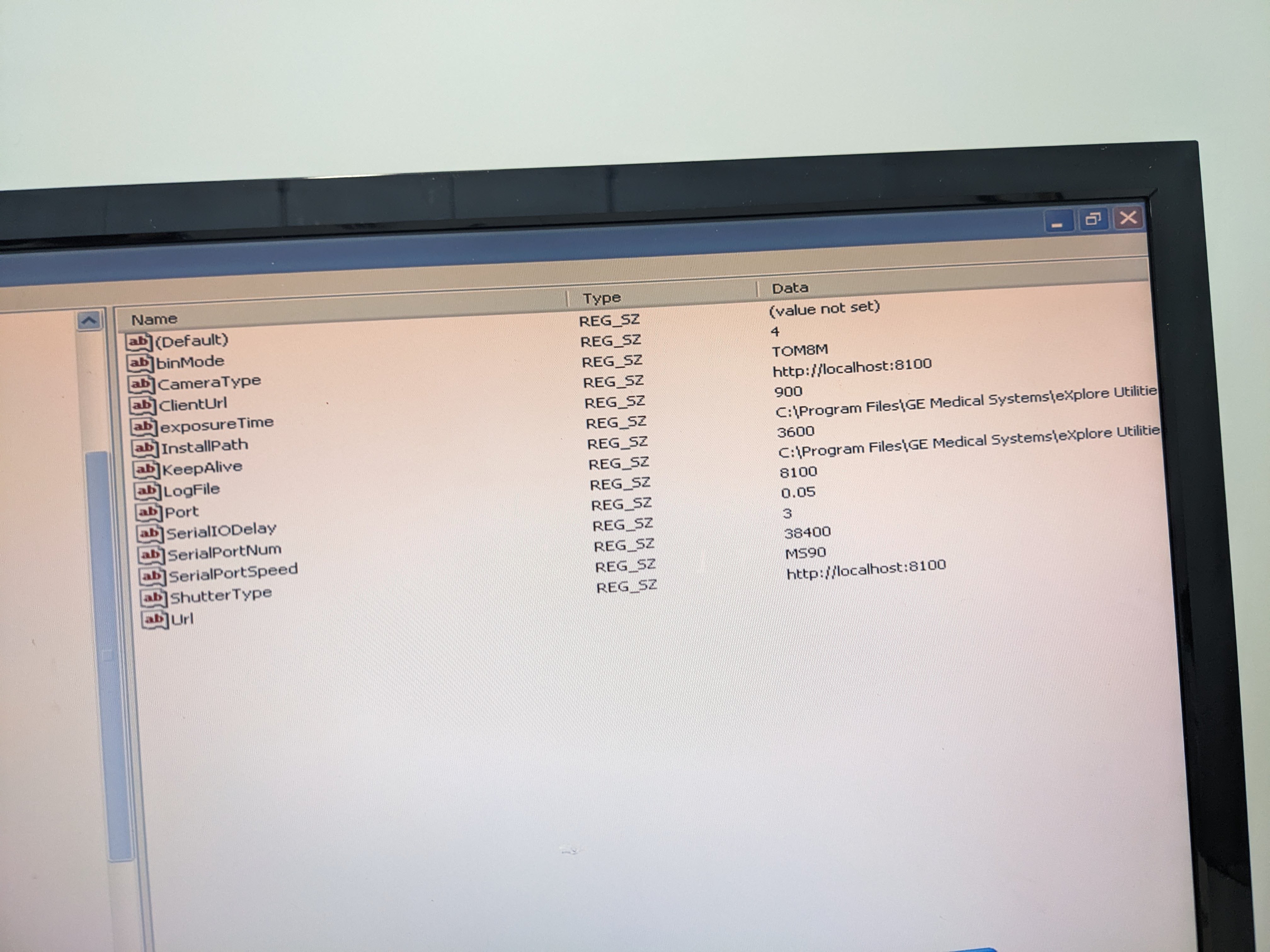
Speaking of that, I took a look in the registry and found flags for "automatic control on" as well as references to the shutter servers being on port 3 (the same as the main controller, for some reason). Unfortunately, flipping these values didn't do anything, at least as far as I can see. Still can't connect to the shutter server, and still can't switch the x-ray control to manual. I would REALLY like to be able to try and get the x-rays to turn on before pulling it out, as a full replacement will be a big (and not cheap) ordeal.
.
![]()
Along with cleaning it, I also greased up the motors and door with some teflon lube (trifoil) that was mentioned in the manual. The only one I'm not sure if I did correctly is the rotary stage, since it can't be turned by hand/screws and stuff aren't visible.
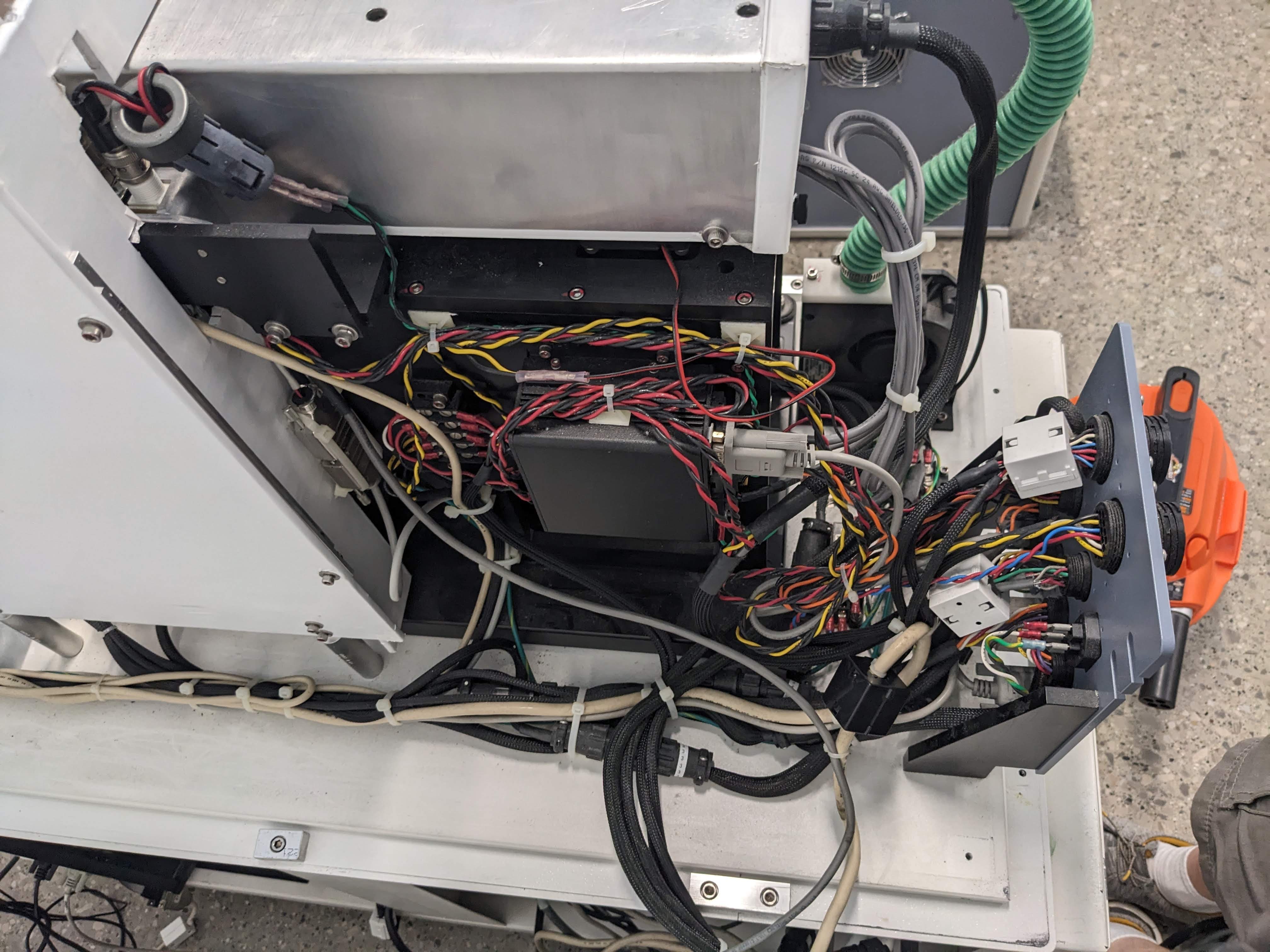
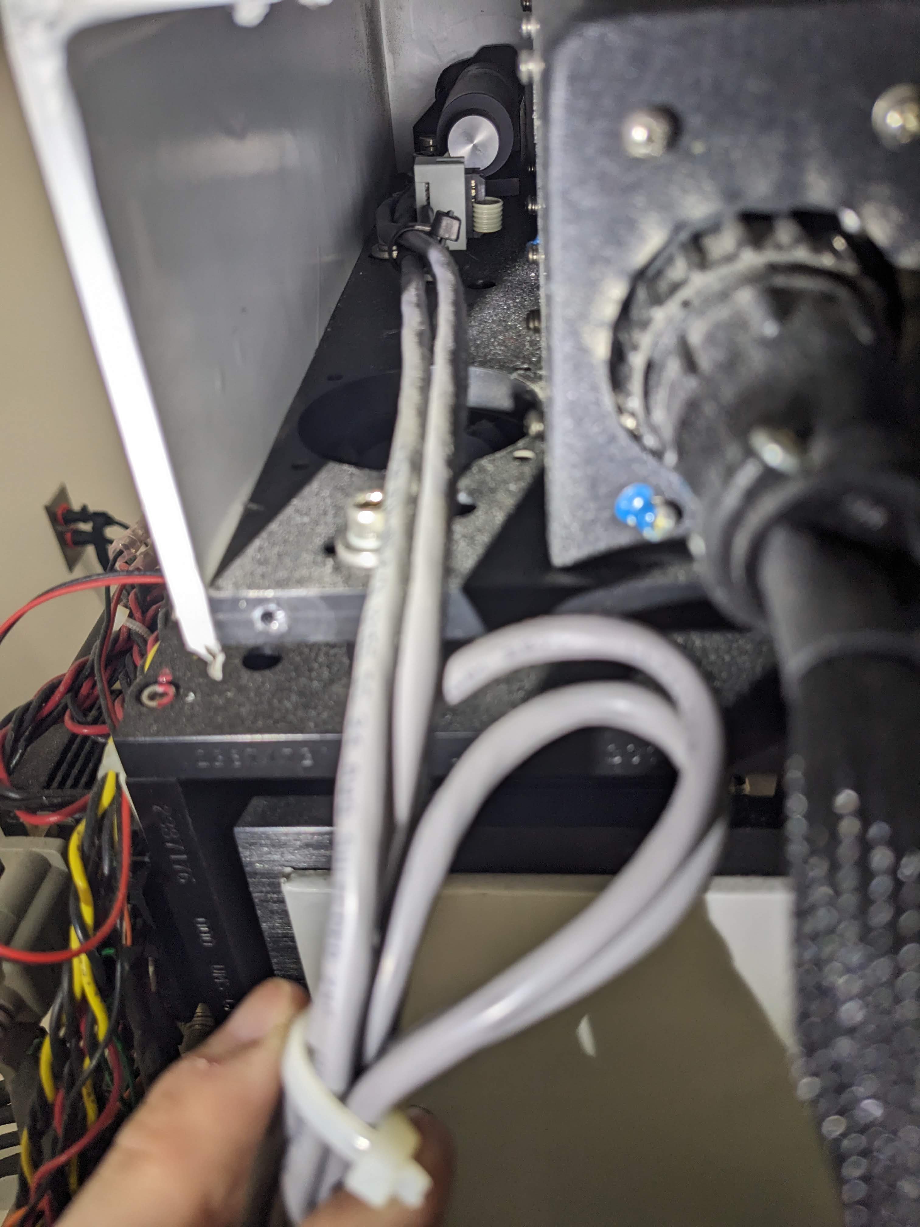
Here's a gallery of the inside that wasn't visible before:
![]()
![]()
![]()
![]()
![]()
![]()
There's some kind of control box, lots of pass-through connectors, and also knobs for adjusting pretty much each axis, as well as the source.
Finally in terms of experimentation for the day, there was a cable that I thought plugged into the shutter (why you no work), but putting a few volts on that didn't do anything. Hmm.
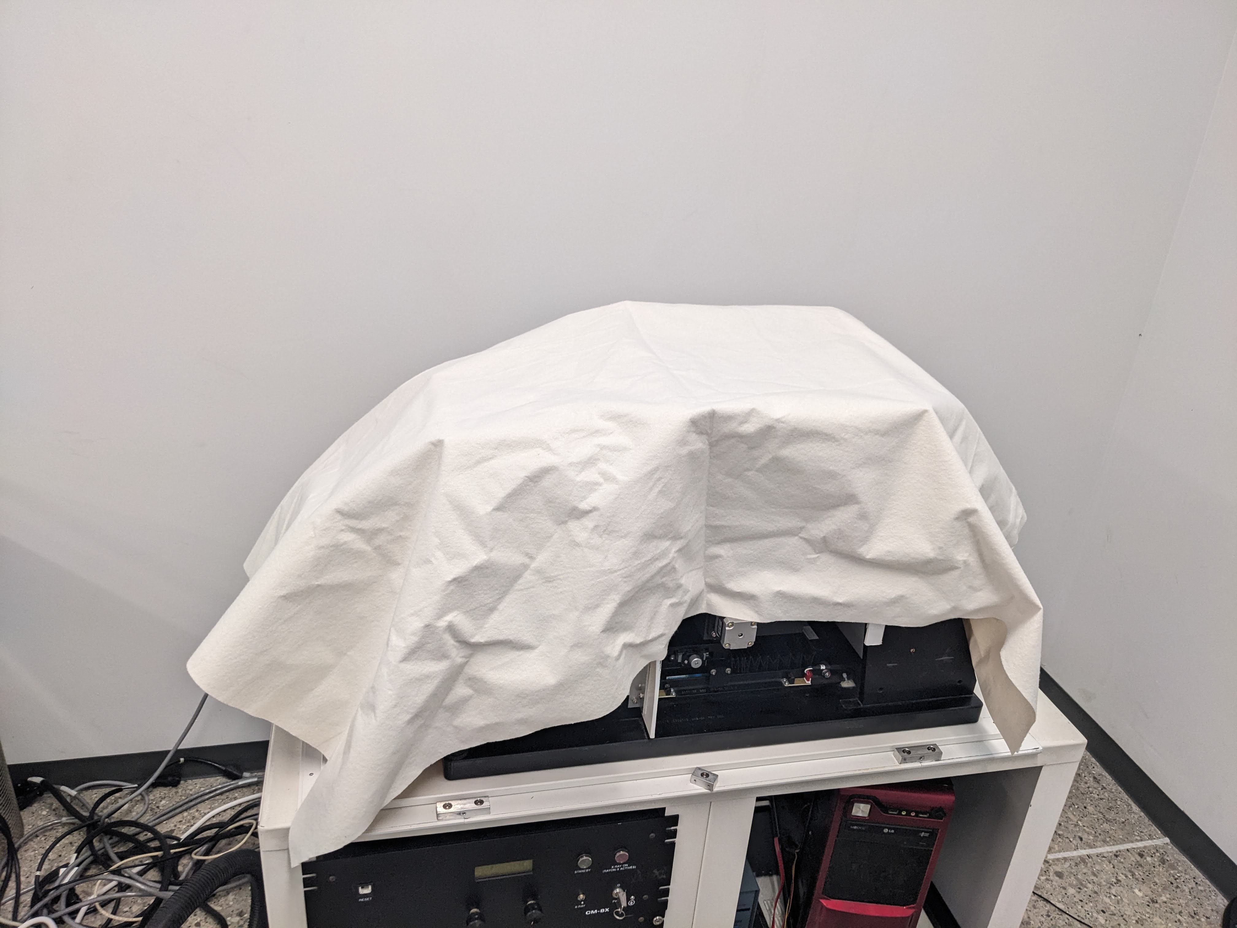
Traveling for work again this week --- the machine will be just covered by a tarp. I'll take another look next weekend, and probably take the rest of the shielding off so I can take a look at the source and see if there's anything super duper obvious (unlikely), which will also serve as practice since I plan on taking the definitely bad source out of the other machine.
![]()
-
A clone of an old drive
07/20/2023 at 19:20 • 0 commentsToday marks some more incremental progress: Successfully cloning with clonezilla a backup of a computer that ran one of these machines way back when (another thanks to Sam from Trifoil). This was a rather annoying process where again I had to learn about computing protocols and whatnot that are now obsolete.
What's prompting me to write this now is that I just got it to actually boot: The hard drive was stuck on an infinite loop at the windows XP loading screen, not a huge surprise, but I was expecting another long an arduous process fixing drivers and whatnot. The solution happened to be much easier: I plugged the drive into a really old computer, where it successfully booted. Then I activated using that new XP activation tool:
And when I brought the drive back to the new computer, whammo! It boots! Woohoo!
Now I get to explore the system, install the drivers for my wifi stick and chrome and serial port card and whatnot, and see if I can do things like turn on that shutter server. And maybe there's a menu for switching on manual mode too. Woohoo!
Edit: I found something I spent quite a bit of time looking for: Files related to the "FGT FRAME GRABBER" and "COMMCAM" software. More keywords: FGT508, ATMEL, CAMELIA, COMMCAM650, THOMPSON, LVDS .
if you find this log through a google search while looking for those files, they're uploaded to the main project page!
Edit 2: had to run out before I could mention this. But I managed to connect to the machine again with this new drive. Already paid a dividend --- there's a utility for conditioning the source and as part of that, it brought the source to 20 KV... And held it there. Awesome! So I know it's stable at 20 KV. I'll bet I can use the serial port monitor to see what kind of signal it's sending to the controller to get it there, and then maybe I can get the x-rays themselves to turn on (i.e heat up the filament) at that voltage.
-
Left access panel, a look inside
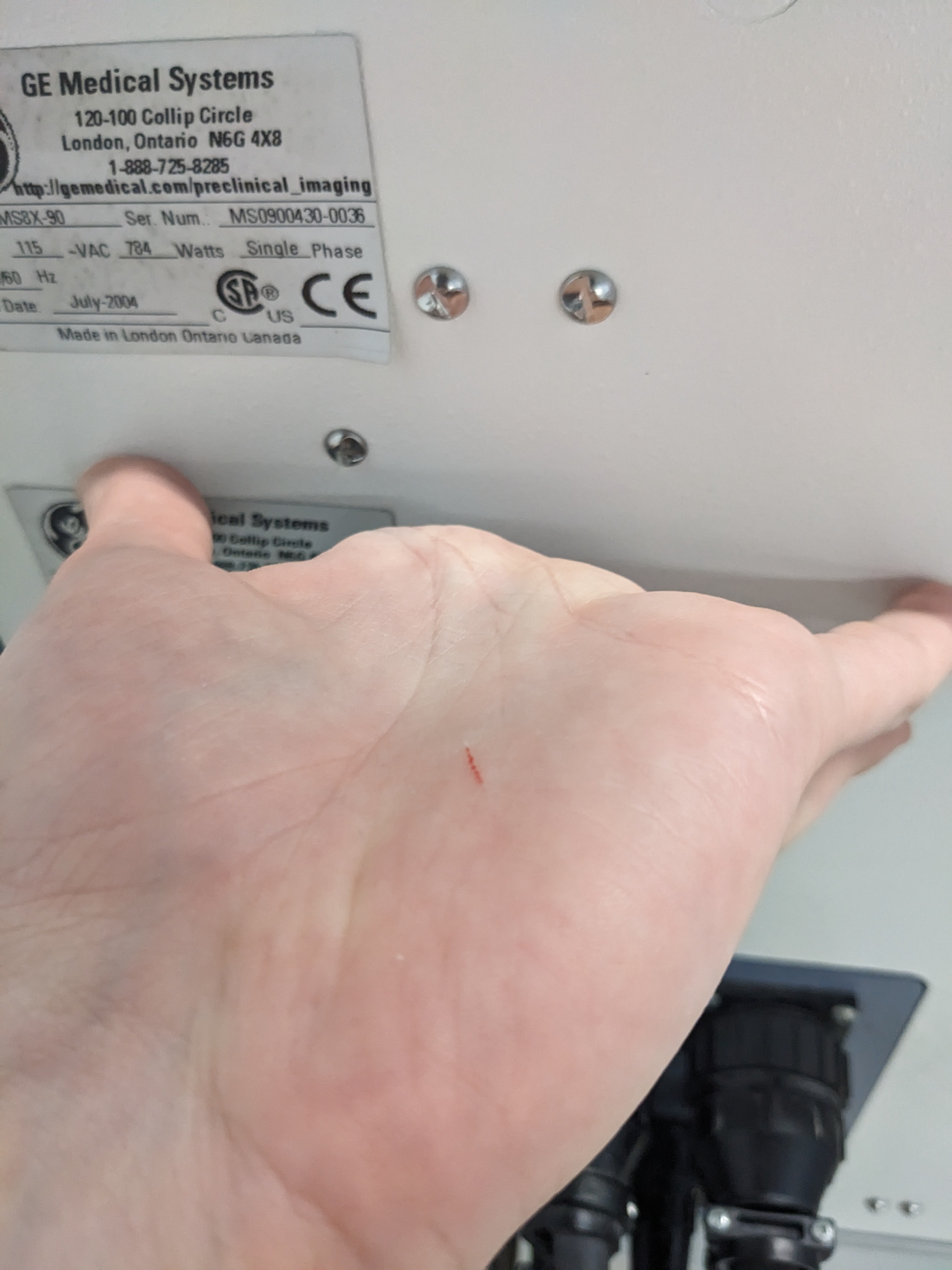
07/10/2023 at 23:16 • 0 commentsAmong finding out that Sam, the guy from Trifoil imaging who has been helping me is leaving, and printing out the service manuals in about a thousand sheets of paper, I took a look inside the left access panel. It turned out to be surprisingly easy, except for cutting myself on one of those damn razor sharp security screws again.
Hopefully there's an easy way to check on the shutter which still doesn't work, and enable manual control of the tube so I can try a lower voltage. Todo: open hatch on right side, as well as main case. Clean and grease everything. Also, install the hard drive backup they gave me into a physical disk.
![]()
![]()
![]()
![]()
![]()
-
Monitoring COM ports and probing data cables
07/09/2023 at 23:02 • 0 commentsJust what any good resurrections project would need: How about some dumps of info found from monitoring COM ports, and checking the resistance and voltage between pins on a data cable?
I found out that:
Signal is sent back and forth in hex that's sometimes translatable to text. For instance, when idling, the log
9701 09/07/2023 14:33:49 IRP_MJ_WRITE UP STATUS_SUCCESS 45 56 53 63 6f 6e 74 72 6f 6c 6c 65 72 05 03 66 06 00 00 00 00 00 00 00 00 00 00 00 00 49 52 4f 4c 44
Translates to:
EVScontroller..f.............IROLD 34 COM3
EVS is the name of the company that first made this system before it was bought by GE. It is likely that "f", or any of several other characters like from "IROLD", is representative of state information like motors running, That string of 0s, by the way, is filled in when doing something. When moving a motor:10884 09/07/2023 14:56:19 IRP_MJ_WRITE DOWN 45 56 53 63 6f 6e 74 72 6f 6c 6c 65 72 ff 03 66 06 20 3a 98 23 28 30 d4 02 58 c0 02 00 49 52 4f 4c 44 EVScontrollerÿ.f. :˜#(0Ô.XÀ..IROLD 34 34 COM3
When turning on the source:
12570 09/07/2023 15:38:29 IRP_MJ_WRITE DOWN 45 56 53 63 6f 6e 74 72 6f 6c 6c 65 72 02 03 66 06 00 27 10 1d 4c 27 10 06 26 c0 00 00 49 52 4f 4c 44 EVScontroller..f..'..L'..&À..IROLD 34 34 COM3
Any ideas about translating the code, let me know. I did not see a difference when trying 40 vs. 45 or 60 kv. Maybe the software always sends the same signal like 40 kv at first, and then when receiving a stable voltage ramps.
in addition, there are signals sent back from the scanner that display basic info in one unit of hexadecimal. For instance, I saw messages like '80' which means 'manual x-ray switch is off', '40' which means "safety door opened", and '04', which means "left switch activated" ( it only checks one axis at a time --- I guess they never move the motors together anyway). I can also see how it tells which motor is active, but again, not what it is actually telling to do.
My immediate goal, was to be able to send a signal lower than 40kv to start --- the tube is rated to 20kv at max current, and probably works at all at a lower voltage. Rather than potentially destroy my tube getting up to 40kv, I'd rather start with a voltage that actually can reach, and maybe keeping it stable there will help it even condition to higher voltages.
The other idea is to look at the actual signal in the cable (#1)/pinout. It has 13 pins. I needed both hands, so I took notes by the incredibly annoying use of voice to text on my phone texting myself which was stupid and annoying.Resistance:
1 is 800 ohm with 2, 900 with 3, 10 ohms with 4, 900 with 5, all others mega ohm range
2 is 100 ohms with three, 900 with 4, 2000 with 5, all others mega ohm range
3 is 1k with four, 2k with five
4 is 1k to 5
everything else is mega ohm range.
Voltage and grounds: Pin 1 is ground to rest of the machine, and pin four is connected to ground through 10 ohms.
The voltage and current which fluctuates on the display when the cable isn't connected, stops fluctuating (shows 0) when pin 7 is connected to ground (voltage) and 8 is connected to ground (current). These are used for feedback on those it seems.
Both of these show approximately 150 mv when being probed. If it's a DC signal then it's not a very large one, though I suppose it could be overflow (from a negative voltage)At all times, tube on/off, there is a potential difference between pins 6 and 12 (6 red wire) of 12 volts. So, power.
And at all times, between 6 and 13, there is a potential of 7.65-7.85 volts. Not sure about this one --- I would have though it would be the voltage setpoint but it's always on. Maybe the controller outputs that by default and the range is really like 5-24 volts or something.
When x-rays are on ONLY, pin 11 is connected to pin 6, otherwise they are unconnected. So it is likely that connecting pin 11 to 6 will turn on the x-rays, while some other combination chooses current and voltage.
And that's all I got for now.
-
Source is conditioning... either that or I'm permanently damaging it
07/08/2023 at 22:04 • 0 commentsDays later, I finally got the time and courage to press that "on" button again for the in-better-shape university scanner. It's been running for almost 2 hours now, and follows the following pattern:
12 kv ---> mid teens --- 20-25 or more sometimes --- a tiny pop --- back to 12. Record I saw, pretty early on, was a peak of 32kv (and I'm setting it to 40kv with no current).
I want to say that the max voltage or average has been rising, but the general behavior here is pretty stable. The tube in question is thus:
https://www.thermofisher.com/order/catalog/product/PXS5925RR
Now, I want to say that this behavior is expected --- or even good. The source has built on conditioning circuits to raise the voltage and drop back down if the current spikes unexpectedly. Which is exactly what I'm seeing here. At the peak voltages in the 20s of kvs, it will sometimes show a couple of microamps at the moment it drops back down.
The question is, whether this process is entirely healthy and removing contaminants from the oil --- or if the occasional popping sound, likely arcing, will actually increase contaminants and permanently damage the tube.
What you want to do is set it to a voltage that it can be stable at for a while, then raise it in small increments. The problem is that while the minimum rated voltage on the catalog is 20kv, and I've seen it get past that regularly, the min set voltage in the actual software is 40kv (max 90). Now, this is super duper duper low by my industrial CT experience standard, but in an ideal case I would go to 20 --- I just don't know how to.
I'm liable to just let it do its thing and run overnight, but this could be a crucial mistake. I could take a step back and figure out how to drive the source manually, and set it to that minimum of 20kv.
Hmm, I say, as i continue to let it do its thing.
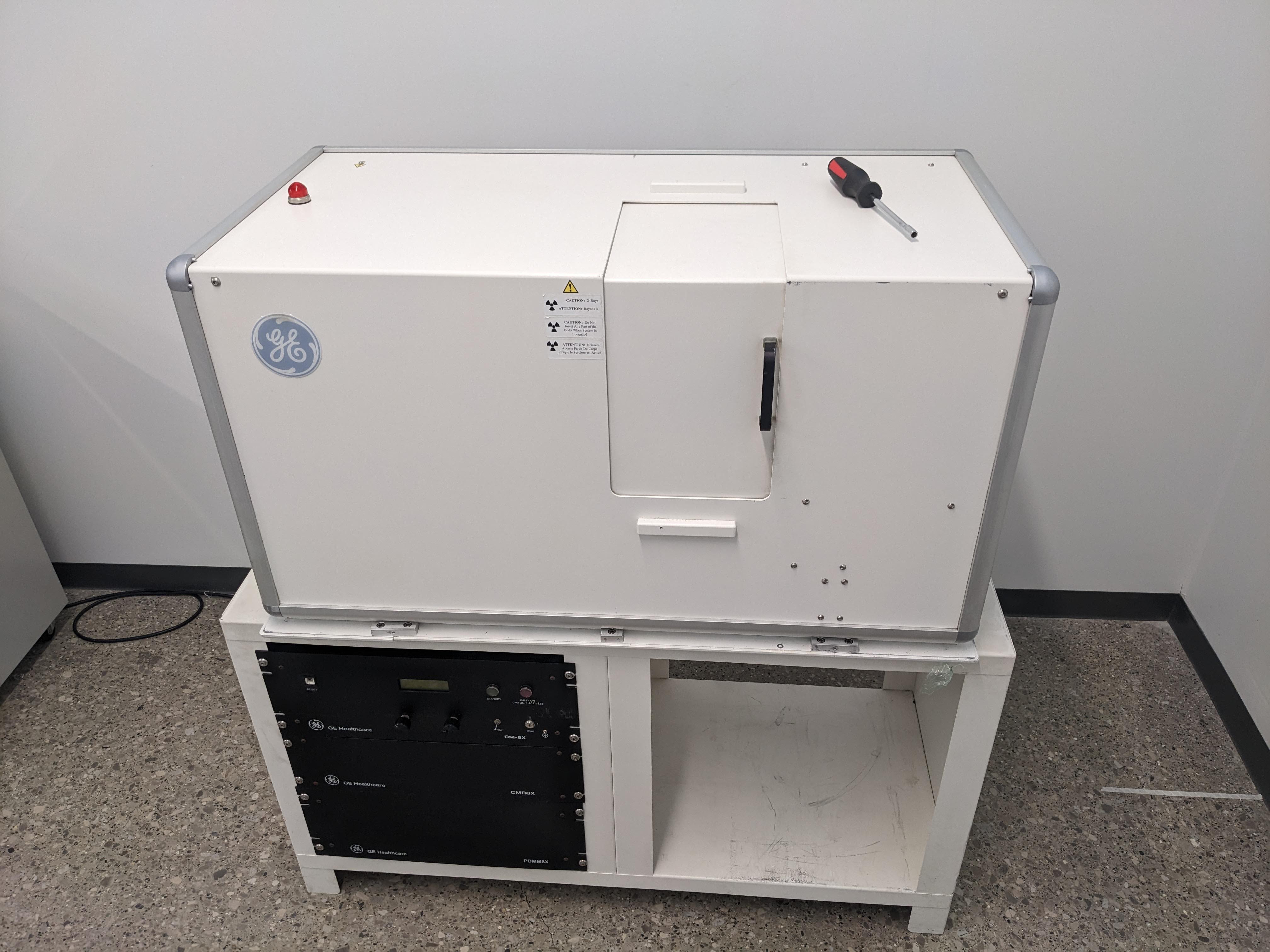
X-Ray CT scanners get new life
Two small GE Explore Locus SPs find a new home, and they happen to be mine.