 BaumInventions
What?
- 2 MCP2515 el cheapo CAN BUS modules.
- 1 Microcontroller of your choice.
How?
Five of the seven lines are shared. Just CS and INT have to be wired seperately for each CAN channel.
INT is used by the MCP board to tell us there is new CAN data waiting.
CS is used by the Microcontroller to tell the MCP board we want to use it.
In this example / project i am using an generic Arduino UNO R3 and the wonderful "MCP_CAN_lib" by Cory J. Fowler to open 2 independent MCP2515 CAN Networks on one microcontroller at once. Make sure you install this library. You can even find it in the integrated library manager of the Arduino IDE.
CAN 0 will use PIN 2 as INT and PIN 10 as CS.
CAN 1 will use PIN 3 as INT and PIN 9 as CS.
I wrote a little test sketch to test your setup.
It generates a CAN message with a random 11bit ID, random length and random Data.
Details about the sent message are printed out over serial.
Then the message is send out over CAN1.
The sketch will also print out details about messages received on CAN0 over serial.
If you connect CAN0 and CAN1 together (L to L and H to H) you should see exact copys of the sent and received message. The CAN library will also output some infos over serial when it has initialised both can modules (or not)...
Wich looks like this:
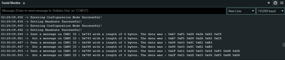
I have set the termination resistors on both CAN modules to enabled (jumper on J1).
Congratulations... You just created a working CAN transceiver.
P.s. i am using a lot of long serial prints in this example... Try not to do that in a real application... CAN is really fast compared to the slow serial we use here... If you have problems receiving messages see if you can make your code faster... NEVER use delays if you want to recieve at the same time or want to build time sensitive applications with CAN.
 George Albercook
 PixJuan
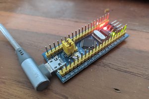
 Athaariq "Eric" Ardhiansyah
 peter ward