 DIY GUY Chris
What you will learn here:
- Circuit design of small board layout with minimum electronics components
- Circuit assembly
- Programming through ISP and test the complete made device
Let's GO!
Supplies
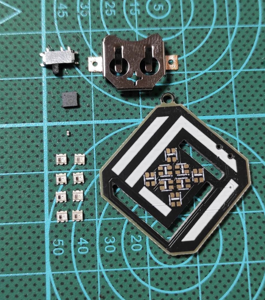
The required ingredients for producing the earring are as follows:
- The customized PCB design (GERBER Files included down below)
- ATtiny13A-MMU AVR Microcontroller
- 8 x WS2812-2020 Addressable RGB LEDs
- 100 nF ceramic capacitor 0402
- SMD Slide switch
- CR1220 Coin Cell Battery holder
![]()
The Circuit Design
I moved to Altium designer and brought the necessary parts to establish a basic schematic, here I used 8 LED pixels connected in series and placed the Attiny alongside with a Coin cell Battery holder and slide switch for power On and Off. I used pin B0 of Attiny to send color data to the pixels.

The circuit will be powered by a CR1220 Coin Cell Battery of 3V and this will not affect the data transmission from Attiny to WS2812 LED registers because considering the LED datasheet the smallest voltage for High level is 2.7V and the smallest voltage for low level is -0.3V then the 3V sent by Attiny to the LED registers will be well interpreted, the 3V will only affect the LED brightness but this is not a limit because I tested the LEDs with 3V power supply and it looks bright enough.
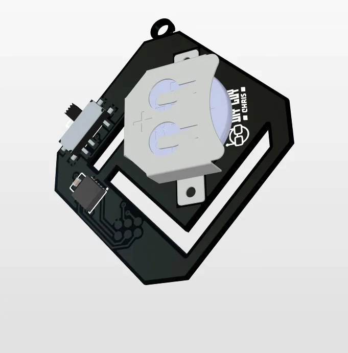
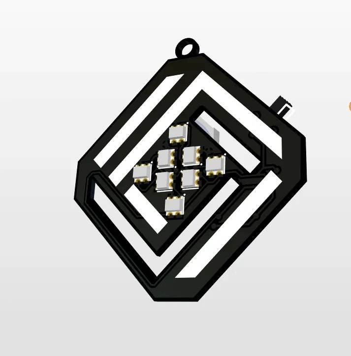
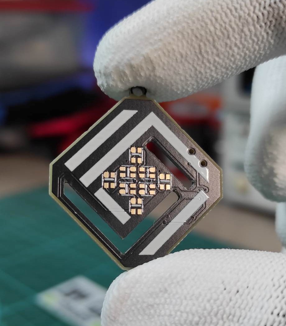
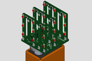
I then transformed the schematic to a PCB design and here I draw the earring shape for board outline where I placed all the small parts, the overall size of the board is 30 by 30 mm, large enough to take the used electronics components, I then draw some inner board shapes to create board cut out slots and I arranged the Pixels to top side. I then placed the rest of the electronics components to board bottom side. I show in my previous project how to program Microcontrollers through ISP technique and I will use this technique to program the Attiny13 so I made the ISP pins of the microcontroller exposed through a 2 by 3 pads array of 1.27 mm spacing.
Circuit Board Assembly
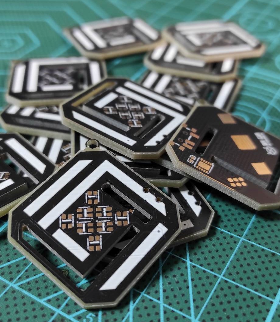
I generated the design GERBER files and sent them to JLCPCB to place a PCB order, I set the boards to be produced in black color and 6 days later the boards have been delivered very well.
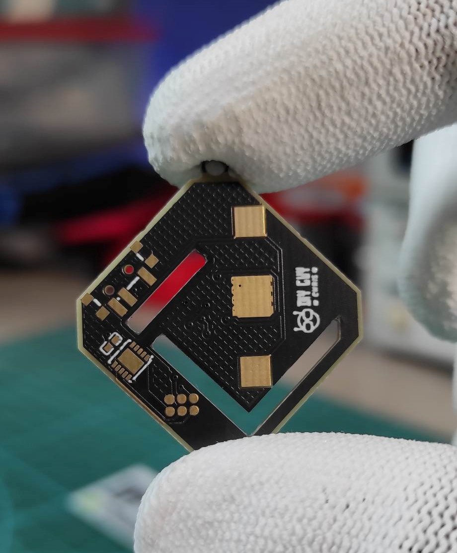
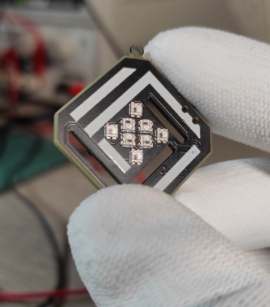
I am all set for assembly so the next step is putting the solder past on the top side components first and place the LED pixels one by one to get them assembled as first assembly side. I used my mini hot plate to perform the assembly and the earring size suits very well the hot surface.
After getting the pixels assembled I then moved to the bottom side and did the same stuff by depositing solder paste to the Attiny pads, the slide switch and the Battery holder, then after placing the components I reflowed the bottom side using a hot air gun. After that, I cleaned the assembled board with some flux removal solvent.

Code And Final Test
Now the earring assembly has been completed so we move to the software part.
I used Arduino IDE to program the pixels so I first need to upload the Attiny bootloader, I used my USBASP as programmer and the small ISP adapter to connect with the Earring board.
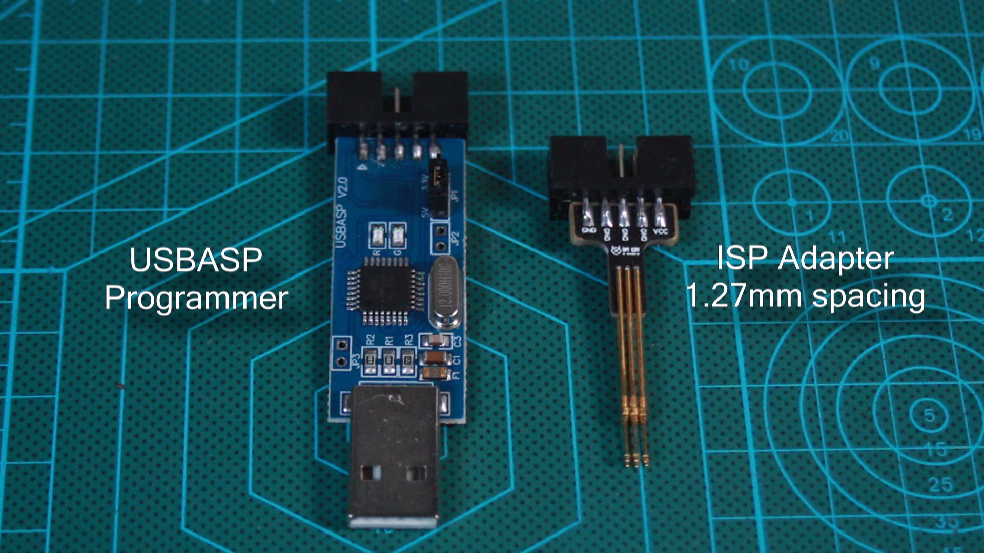
and here I successfully get to upload the Attiny13 bootloader for Arduino IDE programming, now I can upload codes to the earring board and to do this I used this WS2812 library, I write a code that will make the pixels perform some light animations in continuous mode and I uploaded it to the earring board.

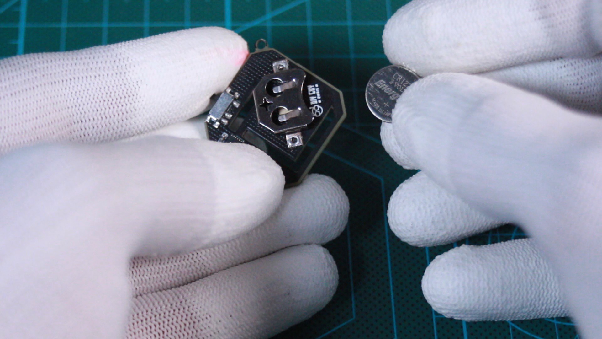
All what I have to do now is placing the coin cell battery and turn on the slide switch and here are the pixels shinning.
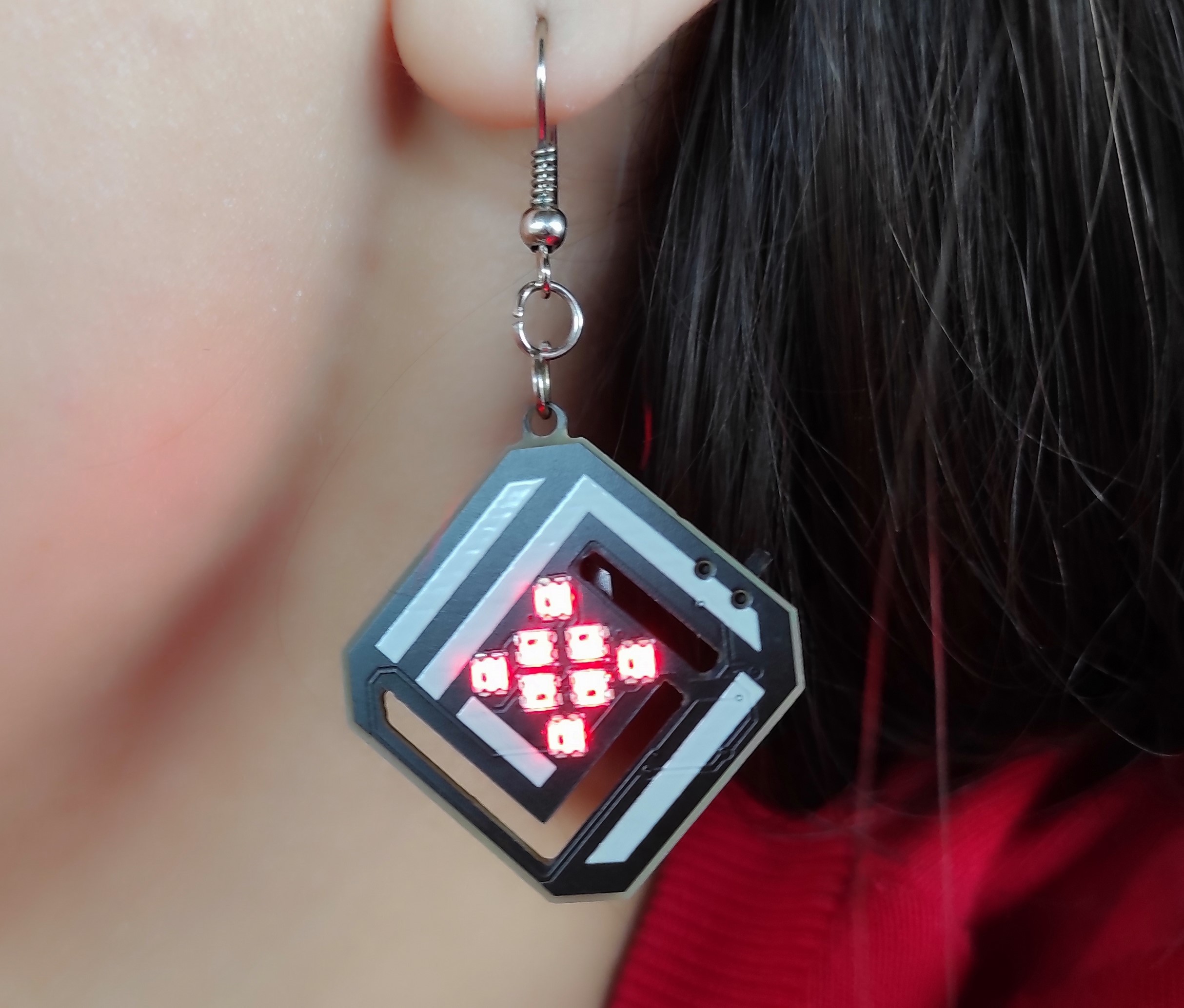
This is a very basic project idea that you can start with if you are willing to produce your own patterns, I am not selling this as ready-made device but you can find in this project all the needed files to reproduce this design, feel free to text when needed!
Enjoy : )

 Abel Rodriguez
 bobricius
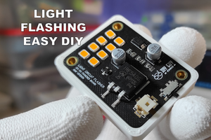
 Anool Mahidharia
>This project will certainly make her happier!
So it won't make him happier? 🤣