 Daniel
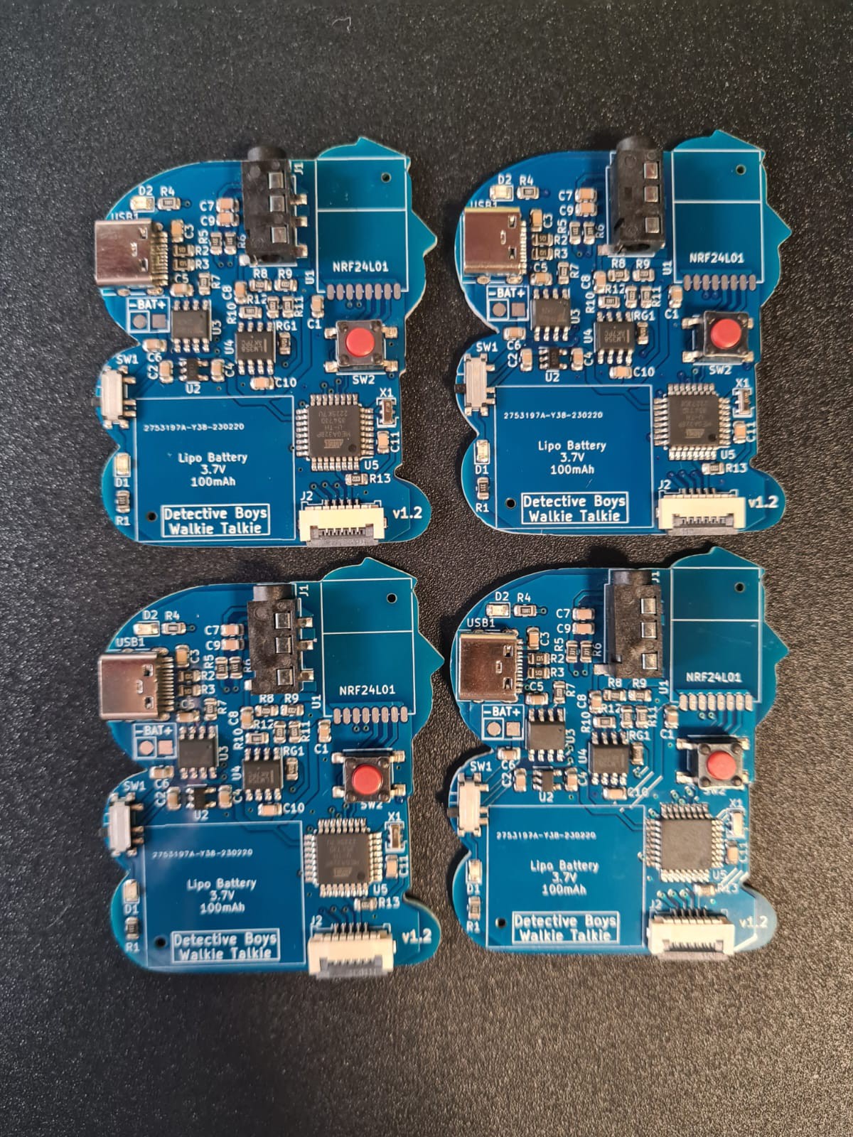
I designed a walkie talkie radio pin badge inspired by Detective Conan anime series using a custom PCB and an ATMEGA328P (Arduino) microcontroller. Integrated rechargable battery, can be charged using any USB-C cable and USB power supply. Thanks to the RF24Audio library I could manage to send the audio using NRF24L01 modules easily with minimal configuration and adjustments.
Easy to use, just plug a headphone pair and press the button to talk to nearby pin badges !
How to use
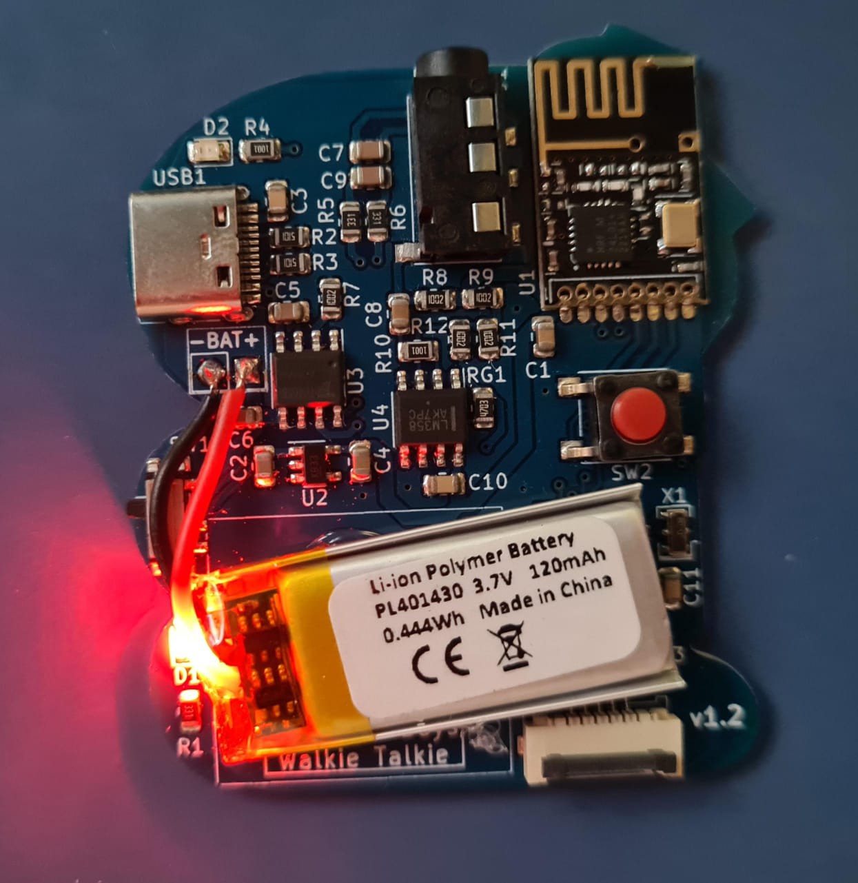
To use the walkie talkie plug any headphones with microphone into the 3.5mm audio jack, then flick the switch on the left side of the board and the LED will light up. Press and hold the button on the board to transmit audio, all the near walkie talkies will receive and play the audio. No pairing or previous configuration is needed.
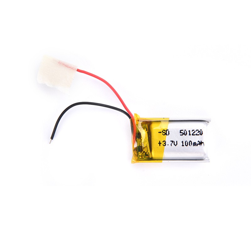
The battery lasts around 4 hours and it can be recharged by plugging an USB-C cable, any cable or power source is compatible. When the battery is charging, the LED near the USB connector will light up, when the battery is fully charged the LED will turn off again. The headphones used may affect on the audio quality, try using different headphones to compare the results.
Technical description
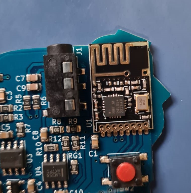
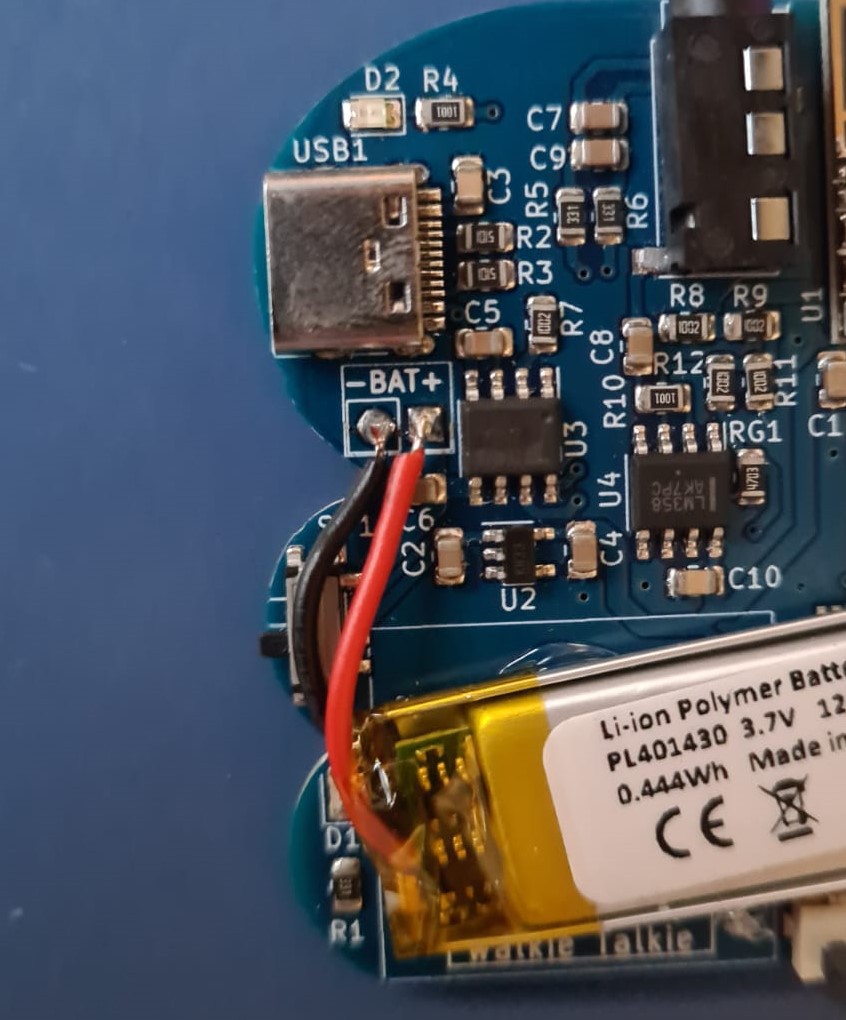
This project uses ATMEGA328P microcontroller on a custom PCB, the microcontrollers sends the audio data using NRF24L01 radio modules, ATMEGA328P microcontroller works at 3.3V 8MHz, you can program it using Arduino IDE and an external programmer like USBTinyISP.
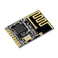
The NRF24L01 radio module is a SMD version suitable for small sized boards, it has a maximum range of 100 meters.
The LiPo battery is directly soldered into the battery terminals of the board, recommended capacity is 100-150mAh.
Some improvements to be made
The short range is the principal handicap of this project, using small and cheap NRF4L01 modules in a board that can fit in the palm of your hand really limits the transmit power of the device, best range I could get was about 30 meters, replacing the modules with bigger ones (with antenna) would probably increase that number.
Audio quality is fine, not great but enough to communicate, quality depends on the microphone that the headphone pair has, so I got different results every time.
 Dan Julio
 ElectroBoy
 JT
JT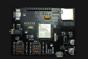
 setCREATE