I was testing the load stage at higher currents today after installing a second MOSFET on the PCB to support a 0.5R load resistor, when I ran in to some bizarre turn-on behavior.
At first I feared this might some complex interaction between the two MOSFETs. Could they somehow be turning on at different times and causing some weird feedback? But why would the current track the change in voltage if it isn't going below the FET threshold voltage? Is the 100k pullup driving the BJT push-pull gate driver stage not enough? I've really gone too far this time.
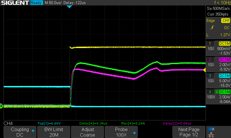
I started probing around as well as varying the frequency and pulse width from the signal generator:
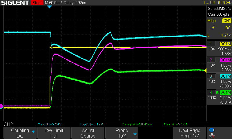
What madness is this? I'd expect the voltage across the load stage to drop a little as the current increases due to the resistance of the cables, fuse, current shunt, etc. You can even see this happening at the very start, but then they start to become correlated. The input voltage drops and the current drops simultaneous...what?
The only thing that would make sense would be the... power supply.
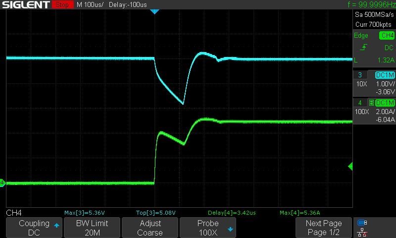
Yup. The bench PSU is messing with me. Both of them, in fact. I have a Korad KA3005P and KD3005D that both show the same behavior. I'm not sure if it's the rapid change in current, or the somewhat inductive load, or something else. I'm just glad this isn't my problem this time!
I switched to the server PSU I'm using for a lot of this testing since it can supply 100A at 12V and the issue went away.
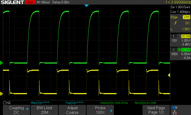
Looks at those beautiful 22A 100us current pulses! You can clearly see how the inductance of the 0.5R load resistor is limiting us here. Pay no attention to the ugliness of the FET_EN signal. I think that's caused by current actually flowing back through the scope's earth connection to the PSU, since ground isn't ground when you're swinging this much current around over cables. That'll have to be its own blog post.
In case anyone is keeping tracking, this means the 8R, 4R, 2R, 1R, and 0.5R load stage configurations are working successfully, which covers a current range of 1.5A to 25A respectively. Tomorrow I'm going to assemble a 0.1R load stage that has to work at 122A, that's where things get serious.
Discussions
Become a Hackaday.io Member
Create an account to leave a comment. Already have an account? Log In.