While not nearly as easy to photograph as other parts of the project, the firmware has been a big undertaking in the project, and it was my primary focus through August.
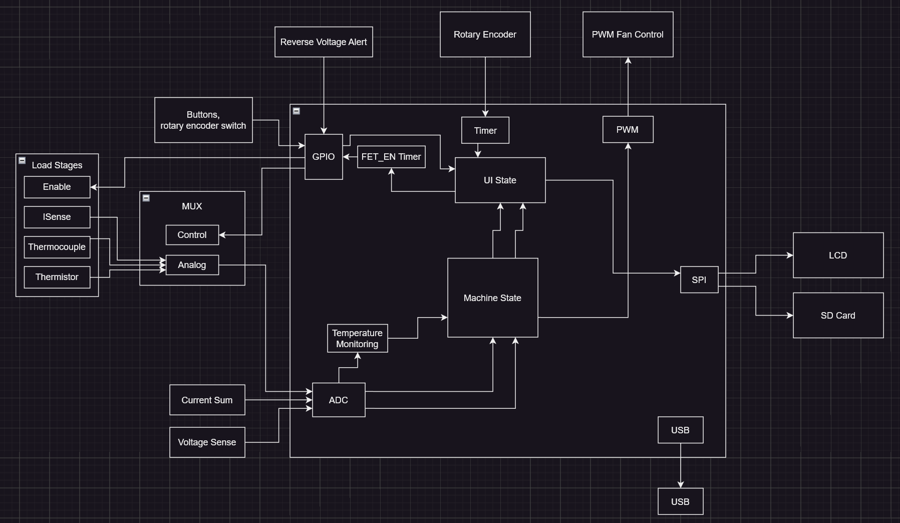
The firmware has to manage a number of different things, many of which are somewhat interdependent:
- Provide a GUI for the screen
- Handle the buttons, and rotary encoder for the user input
- Measure the voltage at the input and the current through the entire system (analog current sum)
- Measure the current through each of the load stages
- Sample the thermistor and thermocouple signals from each load stage and implement software cold junction compensation
- Control the fan speed based on those calculated temperatures
- Calibrate the load stage conductances
- Solve for the optimal load stage selection for a given requested current
- Rapidly switch the selected stages on and off during pulsed mode with precise timing
(Regarding the software, you'll notice I use conductance instead of resistance. This is because the microcontroller can more quickly do a multiplication operation like "current = input voltage * selected conductance", instead of a division operation like "current = input voltage / selected resistance". Also, since there are multiple load stages being enabled in parallel, the conductances of each can just be summed together. Compared with the "inverse of the sum of inversed resistances" calculation you'd do to calculate the equivalent value of multiple resistors in parallel, which is actually just converting them to conductances and back anyways.)
Control Algorithm Overview
(More details for each point below)
- On startup, the conductance of each load stage is measured and stored
- When the user requests a specific current value, the input voltage is measured and used to convert that to a target conductance
- An approximate solution to the subset sum problem is used to determine which load stages should be enabled to get as close as possible to the target conductance, and thus target current.
- This solver is run every 50ms, so any change in input voltage results in a new target conductance to maintain the same current target.
- While a stage is enabled, it's conductance is regularly measured on-the-fly to take into account temperature variations. This live measured conductance is used for the next subset sum calculation.
Subset Sum Problem
One interesting thing I found early on, is that I've apparently have run head first into the Subset Sum Problem. Essentially, there are many different load stages each with a different conductance (mA / A in my firmware). The current value requested by the user is converted to a target conductance using the input voltage, and then the software needs to determine which subset of all possible load stages should be enabled to get as close as possible to that target conductance without going over. Going over would mean drawing more current than the user requested, which might be considered a bad thing in some scenarios.
It turns out that this is a fairly fundamental problem in computer science, and there is no perfect and fast solution. If I had only 8 load stages, I could easily pre-compute the sum for all possible 256 combinations. However, if I have 64 load stages, that's over 18 x 10^18 combinations, so there is no chance our little microcontroller could even store all of those, let alone compute them in under three years.
Fortunately, in this case there is a simple approximate solution, the "Simple 1/2-approximation". Essentially, the firmware just has to take a list of all of the load stages sorted by conductance, select the largest one that fits within the target conductance, then subtract the selected stage conductance, and finally repeat the process with the remaining amount. If the load stages were perfect binary values of each other, this actually would be an optimal solution. However, this leads to another issue: the load resistors have a tolerance of 10% and they also vary substantially as they heat up.
for (int i = 0; i < NUM_STAGES; i++) {
        uint32_t stage_num = load_stages_sorting[i][kStageNum];
        uint32_t stage_conductance = load_stages_sorting[i][kStageConductance];
        bool stage_overpower_OK = StageOverpowerOK(stage_num, vsense_mV) || (GetMode() == kPulsedMode);
        if ((stage_conductance > 0)        //Make sure stage isn't empty
        && ((int32_t)(remaining_conductance - stage_conductance) >= 0)    //and load stage conductance doesn't exceed remaining needed
        && (stage_overpower_OK)
                ) {
            output_config |= ((uint64_t)1 << stage_num); //Set the stage num bit to mark as enabled
            remaining_conductance -= stage_conductance;
        }

    }
A snippet of the subset sum solver. (Note that I'm actually storing the on or off state of the stages as single bit in a 64-bit number. 64 bits for 64 stages.)
Calibration
Presently at startup, the system calibrates each load stage. It does this by briefly enabling each load stage individually for a short pulse, and then simultaneously sampling the input voltage and the current going through the load stage being calibrated. With these measurements, it can calculate the conductance of each stage and store that for future use. This takes care of the manufacturing variance of the load resistors, and the added resistance of the connectors and cables, but still doesn't account for the temperature variation. (It also relies on there being a PSU connected that can handle the 100A+ pulses from enabling a 0.1R load stage. In the future I'll store the calibration data using EEPROM emulation on the STM32 to avoid this. I'm also not even starting to go into the issue with non-linearities as the input voltage approaches the 3V minimum, where the FETs aren't fully turned on.)
To compensate for the temperature variation, the system will periodically do what I call a "live calibration", where it measures the input voltage and the current going through a stage while it is turned on. It then uses the live calibration conductance value instead of the value measured at startup. In effect, as a load stage gets hot its conductance drops and so it goes further down the sorted list for the subset sum solver, and eventually if another stage is a better fit, it is selected instead.
This works, but it isn't ideal because you can't live calibrate a stage that isn't enabled. It would be possible for a stage to be enabled, heat up significantly so its conductance decreases, then be turned off. In this case, the software currently would use that last live calibration value for future calculations. However, now the load stage could cool down and so the previous hot live calibration value would no longer be accurate. I'm not sure quite how to solve this one. It might be possible to actually generate and store a conductance vs temperature curve for each load stage and use that to predict what the conductance would be for a given temperature. Or just let the load enable the stage when it thinks it's the right solution, do a live calibration, and then disable it again because the conductance value is updated and it's no longer the best fit.
Other musings and issues
Another issue (or maybe feature?) with this subset sum solver approach is that it will never produce a solution that results in a higher conductance that requested. If the user requests 12A of current, the software measures the input voltage, lets say 12V, and determines there should be a target conductance of 1000 mA per V. If one of the 1R load stages is slightly lower resistance, it could have a conductance of 1001 mA/V, and thus it would never be selected. This is the case even if the next closest solution was 500 + 250 + 125 = 875 mA/V (for 2R, 4R, and 8R load stages respectively). Effectively, priority goes to never exceeding the target, at the expensive to possibly higher overall error.
All in all, I'm not sure if this would be considered a closed loop or open loop system. The system never measures the total current and uses that to determine whether to enable or disable load stages, like you'd think a typical closed loop system would.
I suppose the output is controlled based on a prediction of how the load stages will respond. Then the factors used to create that prediction, the conductance values, are actively measured. However, if the actively measured conductance values are then used to calculate the output, is that feedback?
I've admittedly never worked with real control loops like PID before, but I'm not even entirely sure how you'd apply something like that to this system. Would you have the control algorithm adjust the target conductance fed into the subset sum solver, so it isn't directly correlated to the input voltage and requested current? Perhaps you could use that "target conductance = target current / input voltage" as a starting point? (feed-forward?)
Either way the fact that the system is just a bunch of huge resistors means it is all at relatively predictable, at least within 10%. And that means even running in pure open loop where you'd just enable specific stages based purely on their nominal rating with no calibration, you can get fairly close.
This idea of running in open loop control is somewhat how the system operates when in pulsed mode. It uses the startup calibration data but doesn't do any live calibration. It would be possible to do live calibration during the pulses as long as they are long enough, though.
To wrap up, I'll say that the most difficult piece of all of all of this for me was...the GUI. As usual, I can make something that works, but making something is functional and maintainable without descending into chaos continues to elude me. Maybe next time. (Or actually I might try out implementing LVGL instead of making my own from scratch.)
Discussions
Become a Hackaday.io Member
Create an account to leave a comment. Already have an account? Log In.