 Michael Gardi
Really Mike, why a TMD-3?
Before I talk about what TMD-3 will be, I would like to give a brief overview of Turing machines, the TMD-1 and TMD-2 designs, and what prompted me to want to do a TMD-3.
Turing Machines 101
The Turing machine was invented in 1936 by Alan Turing. By providing a mathematical description of a very simple device capable of arbitrary computations, he was able to prove the properties of computation in general.
A Turing machine mathematically models a mechanical machine that operates on a tape. More explicitly, a Turing machine consists of (mostly from Wikipedia):
- A tape divided into adjacent cells. Each cell contains a symbol from some finite alphabet. The alphabet contains a special blank symbol and one or more other symbols. The tape is assumed to be arbitrarily extendable to the left and to the right, so that the Turing machine is always supplied with as much tape as it needs for its computation. Cells that have not been written before are assumed to be filled with the blank symbol.
- A head that can read and write symbols on the tape and move on the tape left and right one (and only one) cell at a time.
- A state register that stores the state of the Turing machine, one of many. Among these is the special start state with which the state register is initialized.
- A finite table of instructions that, given the state the machine is currently in and the symbol it is reading on the tape (symbol currently under the head), tells the machine to do the following transition steps in sequence:
- Write a symbol from the finite alphabet replacing the one that was there. Note that the symbol written might be the same as before or different
- Move the head either one cell to the left or one cell to the right.
- Assume the same or a new state as prescribed by the go to state.
About TMD-1
Briefly, Turing Machine Demonstrator (TMD-1) has the following characteristics:
- One tape and one head.
- The alphabet used has three symbols: {0, 1, b}. 0 is the blank symbol and b is a special endmarker.
- There are three states: {A, B, C}. A is the start state plus there is a special HALT state H.
For more details see the TMD-1 project.
The Finite State Machine
The core of a Turing machine is the Finite State Machine, a finite set of instructions that, given the state the machine is currently in and the symbol it is reading on the tape (symbol currently under the head), tells the machine how to transition to the next state of the computation. These Finite State Machines are usually described in one of two ways. As state transition diagrams:
or as state transition tables:
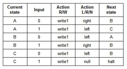
Both of the above describe the same 3-state 2-symbol "busy beaver" program.
Programming a Turing Machine
When building a physical Turing Machine Demonstrator, these definitions must somehow be translated into something that the machine can understand. I have seen these state transitions encoded onto paper tape or expressed as pegs on a 2-dimensional board. Since this project is supposed to be an easy to use Turing Machine Demonstrator, I wanted this "translation" to be as simple as possible. Then it struck me, "What if the state transition table and the Finite State Machine input were one in the same?".
The Tile Interface
So this is what the input area for TMD-1 looks like, a state transition table.
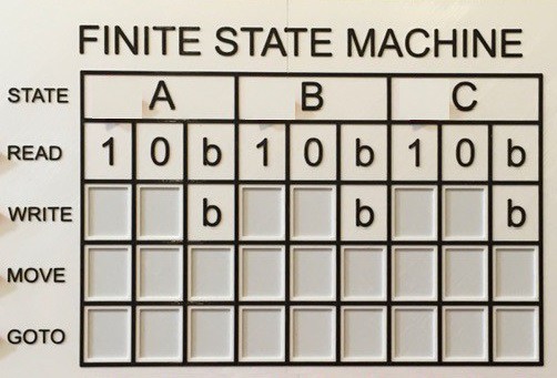
The blank boxes in the table above have shallow rectangular depressions into which appropriately labeled "tiles" can be set: 1/0 for Write, L/R for Move, and A/B/C/H for Goto. TMD-1 is able to "read" these tiles to determine the definition of the state machine. I was inspired to use tiles based on the popular tile based board game "Azul" . Without a doubt the tile interface is what helped me achieve my simple to program easy to understand design goal.
Reading Tiles
Once I determine how I wanted the Finite State Machine input to work, I had to figure out how to make it work. My first idea was to use magnetic reed switches, but I had been looking for an excuse to play around with hall effect sensors. So I ordered some SS451A Omnipolar Magnetic Switches from Digi-Key.
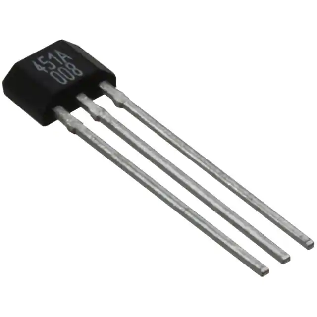 These on/off switches can be triggered by the presence/absence of a magnetic field (and omnipolar means that it doesn't matter what the polarity of the magnetic field is).
Thus tiles can be identified based on their row and a "magnetic" signature. Tiles placed in the Write row are considered to a 0 or 1 based on the absence or presence of a small magnet embedded into the tile. Similarly the Move row assumes the placement of R and L tiles. The Goto row must recognize four different tiles (A, B, C, and H) so two magnet positions are used to create four unique identities. A total of 33 hall effect sensor switches are required to read the TMD-1 state transition table.
About TMD-2
Turing Machine Demonstrator Mark 2 (TMD-2) was created primarily because I wanted a machine capable of demonstrating more complex problems. TMD-2 has the following characteristics:
- One tape and one head.
- The alphabet used has 6 symbols: {0, 1, 2, 3, 4, 5/b}. 0 is the blank symbol and b is a special endmarker.
- There are six states: {A, B, C, D, E, F}. A is the start state plus there is a special HALT state H.
For more details see the TMD-2 project.
Keeping the Tile Interface
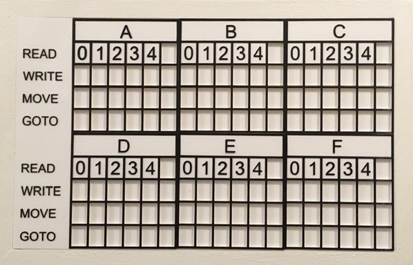
I definitely wanted to keep the tile interface for TMD-2, but there was a problem. Here is the state transition table for TMD-2.
If I continued to use the SS451A hall effect switches, for each state I would need:
- 3 switches for each Read/Write row entry to encode the 7 possible symbol values 0, 1, 2, 3, 4, 5, b (3x7=21)
- 1 switch for each Move entry to encode the 2 possible direction values L, R (6)
- 3 switches for each Goto entry to encode the 7 possible state values A, B, C, D, E, F, H (3x6=18)
So 45 switches for each state. 6 states would thus require (45x6=270) omnipolar hall effect switches. At the time that I was thinking of making TMD-2 I was paying more than $2.00 (CAD) per switch (this price has come down quite a bit and is now around 40 cents (CAD)), not to mention the overhead of managing and reading that many switches. This is why, at the time, I decided to use an elevated camera and Optical Character Recognition (OCR) software to "read" the state definition table tile values.
What I Missed and Why I Want To Make a TMD-3
TMD-1 was the first time that I had ever used a hall effect sensor, so maybe I can be forgiven for missing the fact that there are actually two types. The SS451As that I used are just digital switches, ON in the presence of a magnetic field and OFF when no magnetic field is in proximity. The other type of hall effect sensor, that I just recently became aware of, measures the strength of a magnetic field, not just the presence. These parts are analog based, and a good example is the SS49E Linear Hall Effect Sensor. Game changer!
It occurred to me that by somehow varying the strength of a magnetic field within a tile I could determine the difference between many tile values with just a single sensor. More good news, I can source the SS49E sensors for just 50 cents (CAD) each. So I ordered a bunch.
Testing
I wanted to determine how well this idea would work. I thought that the strength of a magnetic field within a tile could be varied by either embedding different sized magnets, or by using the same size magnet but varying their distance from the sensor. I created a "tile reader" with a single SS49E sensor and some test "tiles".
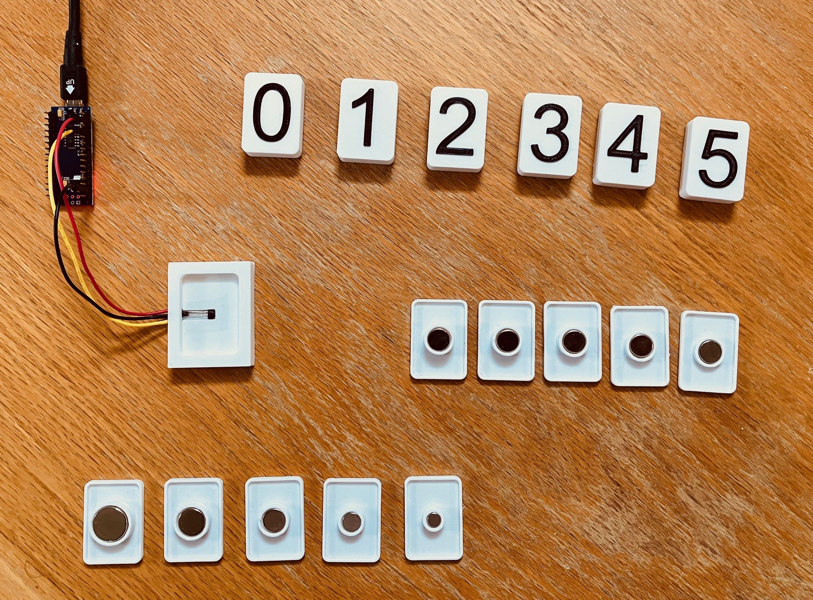
The reader was connected to an Arduino Nano with the following simple sketch loaded.
int sensorPin = A0;

// Select the input pin for sensor.
int middle = 0;

void setup() {
    // Setup serial output.
    Serial.begin(115200);
    Serial.println("Hall Effect Encoder Test!");
    middle = analogRead(sensorPin);
}

void loop() {
    // Read the value from the sensor.
    int sensorValue = analogRead(sensorPin);
    Serial.println(sensorValue-middle);
    delay(500);
}
One thing that I discovered is that the default reading from the sensor (with no magnetic field nearby) is the middle of the range. Furthermore a magnet with one polarity will move the reading to higher values while the opposite polarity moves it to a lower values. This is why I initialize "middle" in setup().
The bottom row of test tiles (as pictured above) uses five different sized magnets all positioned 2 mm from the sensor. Here are the results that I got reading them.
| Magnet Size | 15 mm | 10 mm | 8 mm | 6 mm | 3 mm |
| Polarity 1 Values | 63 | 81 (1) | 50 (2) | 82 (1) | 48 (2) |
| Polarity 2 Values | -60 | -81 | -50 | -82 | -48 |
You can see from (1) that there is hardly any difference between the 10 mm and 6 mm magnet values. Similarly for (2) the 8 mm and 3 mm magnet values show no separation. With the margin of error in reading the values, different tiles based on this method would certainly be indistinguishable from each other.
The middle row of test tiles (again as pictured above) uses five identical 8 mm magnets positioned 5 mm, 4 mm, 3 mm, 2 mm, and 1 mm from the sensor. Here are the readings.
| Magnet Distance | 5 mm | 4 mm | 3 mm | 2 mm | 1 mm |
| Polarity 1 Values | 37 | 48 | 62 | 74 | 88 |
| Polarity 2 Values | -34 | -45 | -58 | -85 | -95 |
This is much better. These readings have a much better distribution with at least a 10 point difference between them. I guess I shouldn't be surprised since the part has linear in it's name.
Finally, the top row of tiles is the same as the middle row but but uses 6 mm magnets instead of 8 mm and I didn't create any reverse polarity tiles.
| Magnet Distance | 5 (6 mm) | 4 (5 mm) | 3 (4 mm) | 2 (3 mm) | 1 (2 mm) | 0 (1 mm) |
| Polarity 1 Values | 2 | 20 | 24 | 35 | 68 | 81 |
So again pretty good distribution although the close proximity of the 3 and 4 tile values is worrying. I'll have to look into that. Nevertheless, these tests convince me that by using a single 50 cent linear hall effect sensor I can easily distinguish between up to 10 different tiles. More than enough for my TMD-3 state transition table input. Furthermore by using 2 sensors this number goes up 100 different tiles.
About TMD-3
TMD-3 will be quite similar to the Mark 2 version. By using SS49E linear hall effect sensors, Turing Machine Demonstrator Mark 3 will do away with the need for TMD-2's overhead camera and OCR software. At the same time I would like to make the whole unit more compact and portable, perhaps with a pull out drawer to hold the tiles. I'm not sure if anyone would want to use TMD-3 in an educational setting, but my goal is to make it more suitable for such.
I'll keep the backend Raspberry Pi 4 and 7 inch touch screen monitor and use the existing Python based software modified to use the new state definition table inputs.
TMD-3 has the following characteristics:
- One tape and one head.
- The alphabet used has 5 symbols: {0, 1, 2, 3, 4/b}. 0 is the blank symbol and b is a special endmarker.
- There are six states: {A, B, C, D, E, F}. A is the start state plus there is a special HALT state H.
Notice that I have reduced the number of symbols by 1. TMD-3 will be a 6-state 5-symbol Turing machine. This does not reduce the power of the machine by much but does simplify the design by a lot. TMD-3 will still be Turing Complete (TC).
Design
I'm still thinking things through, but my plan so far is to create a PCB to hold a single state's sensors. By dropping a symbol, each state "board" will now require just 16 SS49E linear hall effect sensors to read the tiles. This is a nice number because each state board will have a 16-channel Analog Multiplexer (CD4067BE) to manage the 16 sensors.
Since most PCB fabricators require at least a 5 board minimum when ordering, making a single state board design will save money. The board will be designed with a "bus" so that six state boards can be easily wired together to create the complete state transition table for TMD-3. The bus will contain the following lines:
Name | Description |
|---|---|
| S0 | S0-S3 are the channel select lines for the CD4067BE multiplexers. All six multiplexers will be set at the same time to the same channel when reading tile values. |
| S1 | |
| S2 | |
| S3 | |
| E1 | E1-E6 are the selected channel outputs from the six state CD4067BE multiplexers. The common state board will have jumpers so that each state can be uniquely mapped to it's own En output. |
| E2 | |
| E3 | |
| E4 | |
| E5 | |
| E6 | |
| VCC | Power |
| GND | Ground |
Since the Raspberry Pi does not have native ADC support, the state board PCB will also have an 8-channel 10-bit A/D converter chip (MCP3008) defined. Only one of the state boards will actually be populated with the chip. Six of the input channels on this chip will be mapped to the E1-E6 selected channel outputs from the six state CD4067BE multiplexers.
To read the entire state transition table containing 96 SS49E sensors, the Raspberry Pi will require only 8 GPIO lines. Four of these will be mapped to the S0-S3 channel select lines for the CD4067BE multiplexers. An additional four lines are required to control the MCP3008 A/D converter chip via its SPI interface to read the sensor values.
The software will iterate through the multiplexers’ 16 channels. For each channel it will read in turn the sensor values of the 6 multiplexer outputs.
So that's the plan. I sure there will be changes when I get "into the weeds". Looking forward to it.
Intermission
This is not really a break. At this point given the background, testing, and design described above I went ahead and built my TMD-3. If you are interested in the details of how this happened I would strongly encourage you to have a look at this project's logs for the complete picture. Here is a handy link: Project Logs. Make sure that the SORT BY: is set to Oldest to get a chronological view.
Conclusions
So here is my finished project.
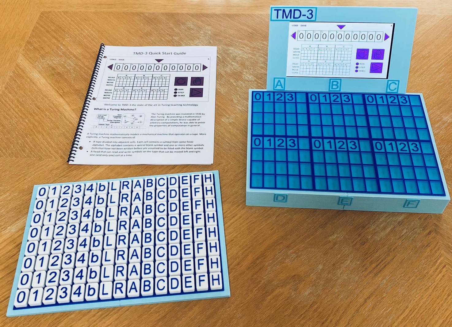
I'm very happy with the result. Using the SS49E Linear Hall Effect Sensors I was able to distinguish between the tiles with great fidelity. The finished product is much more compact than it's older siblings but just as functional and capable.
Some Notes
Or, if you were to start again Mike, what would you have done differently?
I used 6 mm (diameter) imbedded magnets and kept the smaller tiles from the TMD-2 design. As a result, when loosely piled, the tiles tend to clump together. Not a big deal, just a little annoying. I did a bit of testing with smaller 4 mm magnets and set the infill for the tiles to 100% to make them heavier and this seemed to mitigate the stickiness somewhat. At this point I was pretty heavily invested in 6 mm magnet tiles so | decided not to switch. Instead I designed the tile tray seen above with a sheet metal backing to take advantage of the imbedded magnets and keep the stored tiles in good order.
The 7 inch touch screen display is rigidly fixed to the console. One improvement might be to attach the display with hinges so that it could be folded down for transport and to adjust the viewing angle. Similarly attaching the tile tray to the bottom of the console for transport would also be nice.
Having said all that I'm OK with where I have stopped here.
Other Applications
OK so the linear hall effect sensors worked out great for this project, but could they be used for other similar applications? Say for determining different pieces on a game board, like chess for instance. Well the answer is yes with one fairly big constraint. The object being recognize must be place in the exact same position relative to the sensor each time to get an accurate reading. My tiles work because they are placed into shallow indentations which fix their positions. A normal flat chess board would not work, but if you had round indentations in the center of each square of the board and the chess pieces had round bottoms that exactly fit those indentations then yes it could work.
So if you have 10 or so objects to be recognized, and the objects can be placed in fixed positions relative to the linear hall effect sensor, then this might be the answer for you. For more objects you could use multiple sensors.
I actually have a pretty cool new project in mind that I'm not quite ready to disclose yet. Stay tuned.