 Michael Gardi
Really Mike, why a TMD-3?
Before I talk about what TMD-3 will be, I would like to give a brief overview of Turing machines, the TMD-1 and TMD-2 designs, and what prompted me to want to do a TMD-3.
Turing Machines 101
The Turing machine was invented in 1936 by Alan Turing. By providing a mathematical description of a very simple device capable of arbitrary computations, he was able to prove the properties of computation in general.
A Turing machine mathematically models a mechanical machine that operates on a tape. More explicitly, a Turing machine consists of (mostly from Wikipedia):
- A tape divided into adjacent cells. Each cell contains a symbol from some finite alphabet. The alphabet contains a special blank symbol and one or more other symbols. The tape is assumed to be arbitrarily extendable to the left and to the right, so that the Turing machine is always supplied with as much tape as it needs for its computation. Cells that have not been written before are assumed to be filled with the blank symbol.
- A head that can read and write symbols on the tape and move on the tape left and right one (and only one) cell at a time.
- A state register that stores the state of the Turing machine, one of many. Among these is the special start state with which the state register is initialized.
- A finite table of instructions that, given the state the machine is currently in and the symbol it is reading on the tape (symbol currently under the head), tells the machine to do the following transition steps in sequence:
- Write a symbol from the finite alphabet replacing the one that was there. Note that the symbol written might be the same as before or different
- Move the head either one cell to the left or one cell to the right.
- Assume the same or a new state as prescribed by the go to state.
About TMD-1
Briefly, Turing Machine Demonstrator (TMD-1) has the following characteristics:
- One tape and one head.
- The alphabet used has three symbols: {0, 1, b}. 0 is the blank symbol and b is a special endmarker.
- There are three states: {A, B, C}. A is the start state plus there is a special HALT state H.
For more details see the TMD-1 project.
The Finite State Machine
The core of a Turing machine is the Finite State Machine, a finite set of instructions that, given the state the machine is currently in and the symbol it is reading on the tape (symbol currently under the head), tells the machine how to transition to the next state of the computation. These Finite State Machines are usually described in one of two ways. As state transition diagrams:
or as state transition tables:
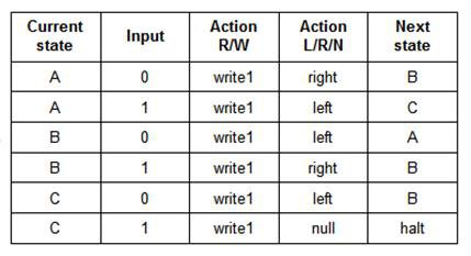
Both of the above describe the same 3-state 2-symbol "busy beaver" program.
Programming a Turing Machine
When building a physical Turing Machine Demonstrator, these definitions must somehow be translated into something that the machine can understand. I have seen these state transitions encoded onto paper tape or expressed as pegs on a 2-dimensional board. Since this project is supposed to be an easy to use Turing Machine Demonstrator, I wanted this "translation" to be as simple as possible. Then it struck me, "What if the state transition table and the Finite State Machine input were one in the same?".
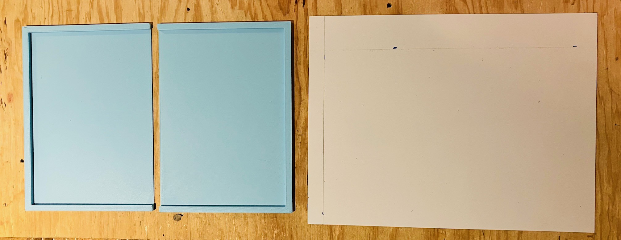
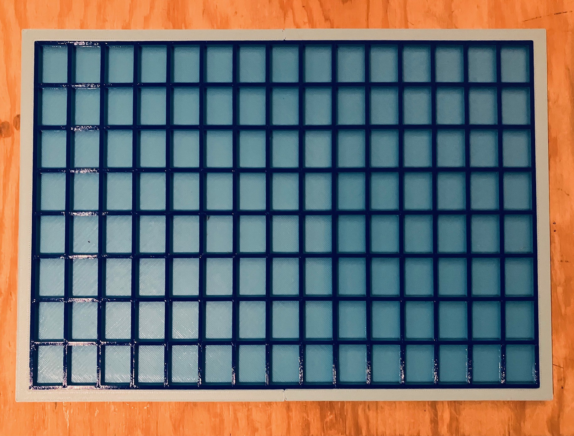
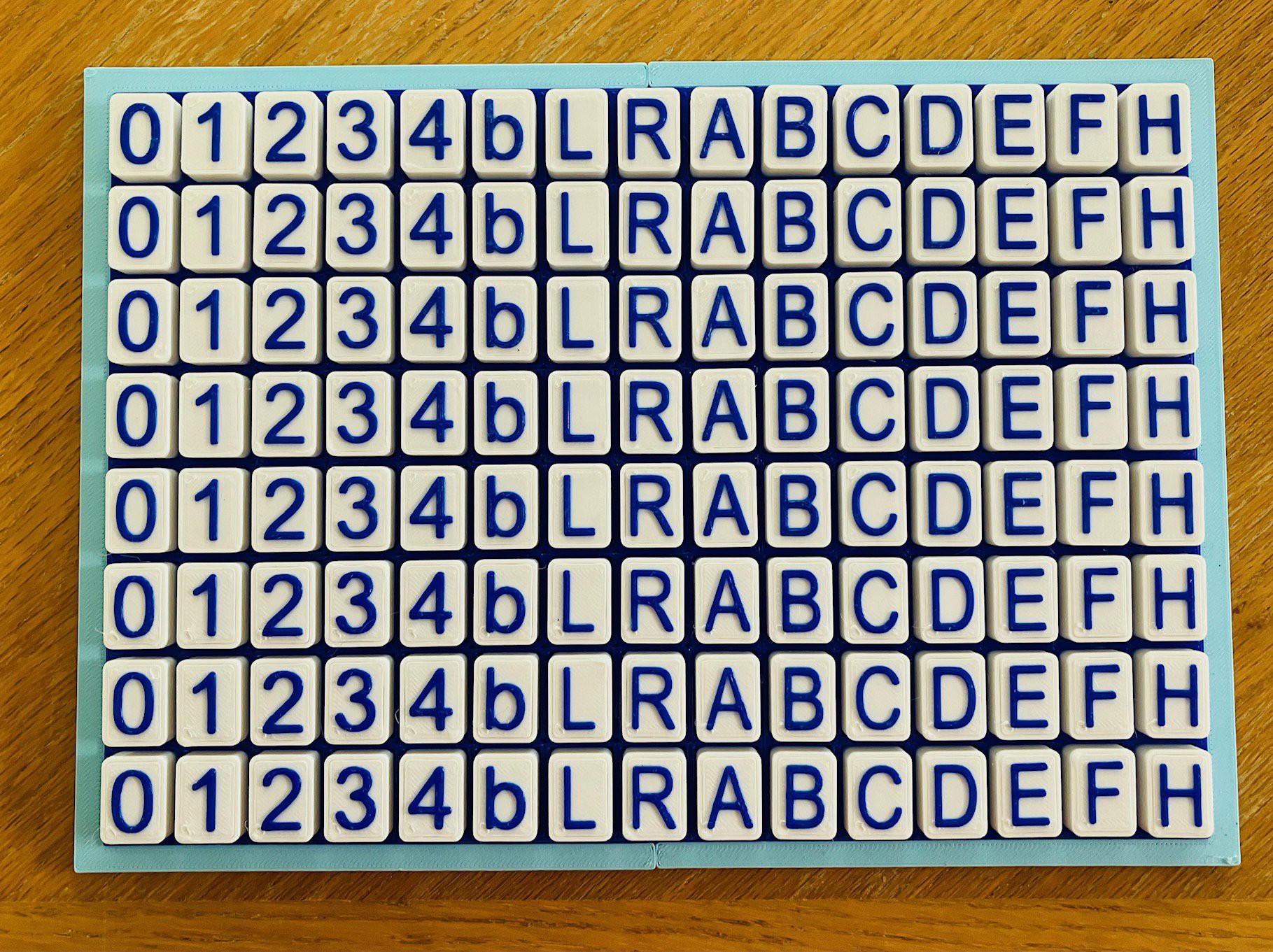
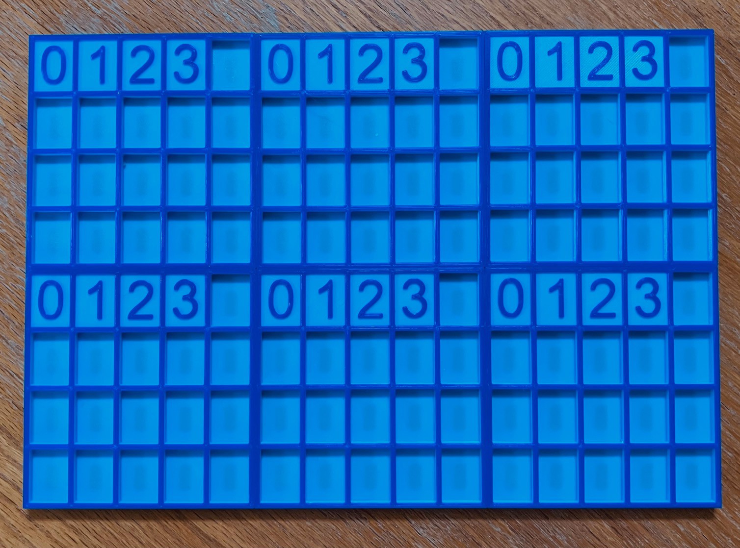
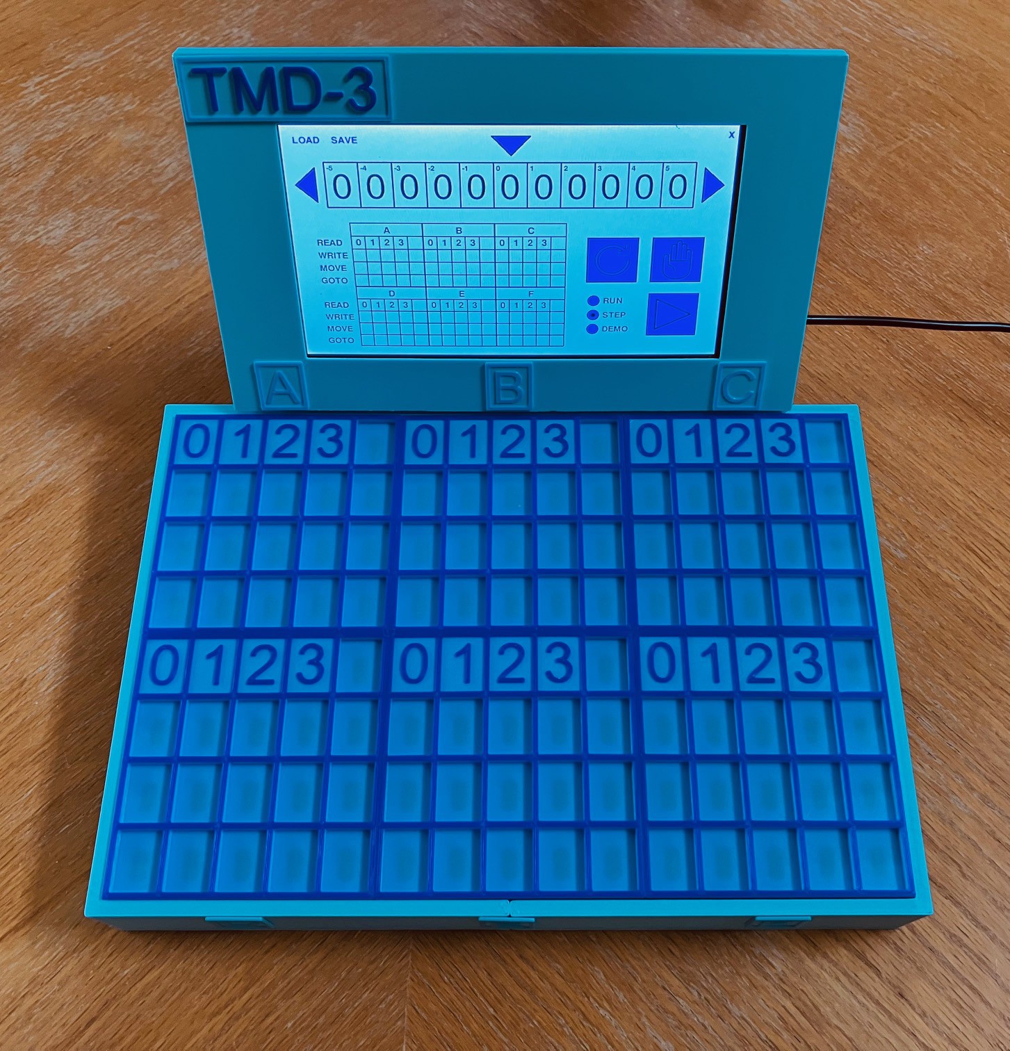
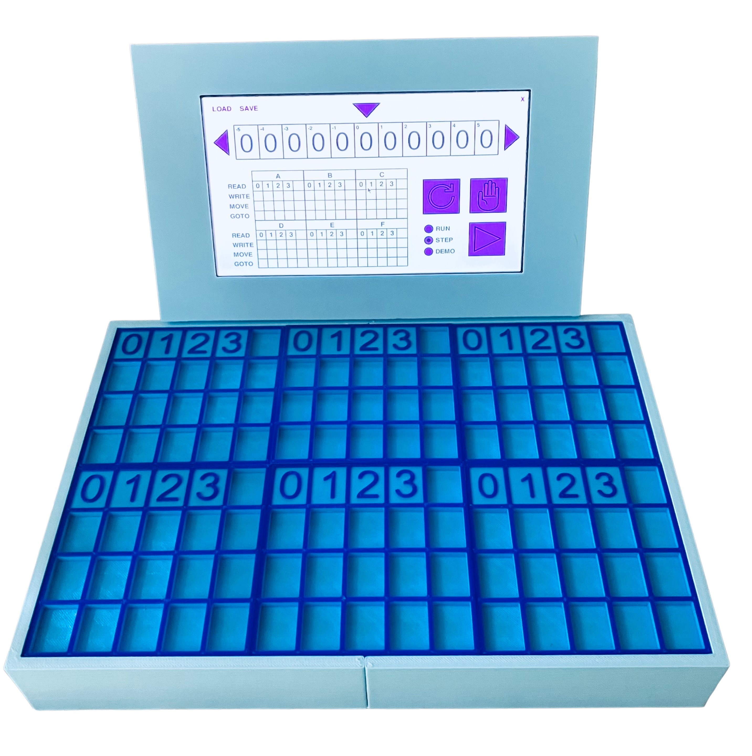
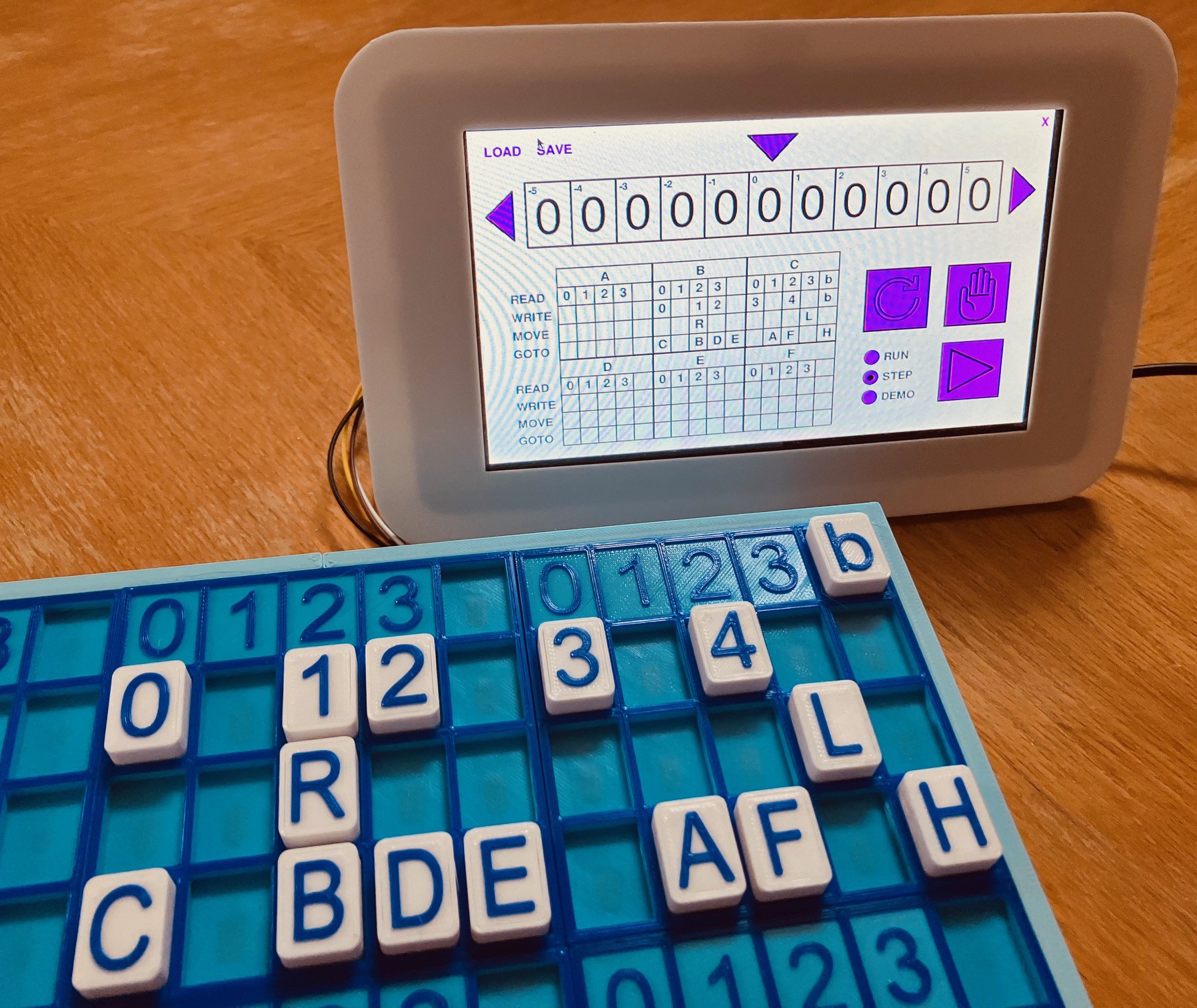
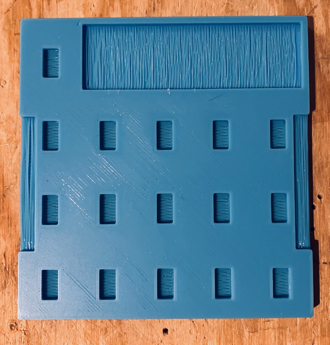
The Tile Interface
So this is what the input area for TMD-1 looks like, a state transition table.
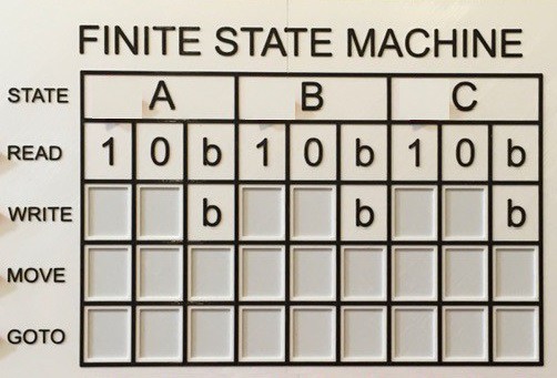
The blank boxes in the table above have shallow rectangular depressions into which appropriately labeled "tiles" can be set: 1/0 for Write, L/R for Move, and A/B/C/H for Goto. TMD-1 is able to "read" these tiles to determine the definition of the state machine. I was inspired to use tiles based on the popular tile based board game "Azul" . Without a doubt the tile interface is what helped me...
Read more »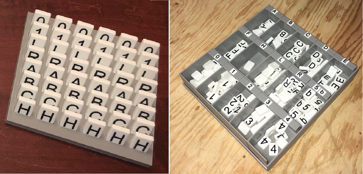


 Al Williams
 Chris
Chris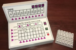
Hey Mike --
Love it! Clever way to reduce the BOM and keep from killing the budget on Hall sensors. Nicely done. Wrote it up for the blog, should publish soon. Thanks for tipping us off!