 Michael Gardi
So I got the second panel integrated into the Console application.
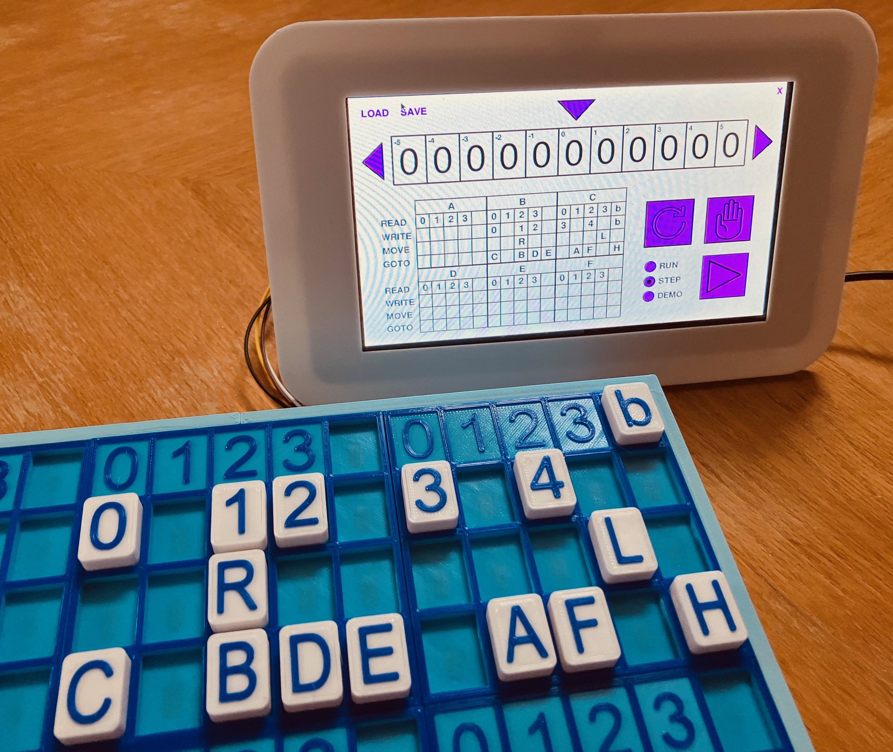
I'm pretty happy with the way that everything is working out and now have the confidence to proceed with the additional four panels.
One thing that I have learned is that there is enough variance between the sensors to warrant taking the time to calibrate each sensor against the tiles that are expected to be placed in that position of the State Panel. I'm sure that despite my best efforts to position each sensor in the precise same position that readings are bound to differ. Calibrating the sensors helps to mitigate the slight difference I am finding between tiles of the same value. Here is what that calibration looks like in my code (so far).
# Sensors connected to channel 0 of the MCP3008 8-channel A/D converter.
# READ row.
sensors[0][8]["tiles"] = [(-621,'b'), (275,'4')]

# WRITE row
sensors[0][4]["tiles"] = [(-493,'0'), (-339,'1'), (768,'2'), (474,'3'), (339,'4')]
sensors[0][5]["tiles"] = [(-454,'0'), (-301,'1'), (678,'2'), (429,'3'), (307,'4')]
sensors[0][6]["tiles"] = [(-403,'0'), (-282,'1'), (627,'2'), (390,'3'), (282,'4')]
sensors[0][7]["tiles"] = [(-397,'0'), (-275,'1'), (614,'2'), (384,'3'), (282,'4')]
sensors[0][9]["tiles"] = [(-390,'0'), (-275,'1'), (589,'2'), (371,'3'), (266,'4')]

# GOTO row
sensors[0][0]["tiles"] = [(-230,'L'), (237,'R')]
sensors[0][1]["tiles"] = [(-218,'L'), (224,'R')]
sensors[0][2]["tiles"] = [(-205,'L'), (205,'R')]
sensors[0][3]["tiles"] = [(-198,'L'), (205,'R')]
sensors[0][10]["tiles"] = [(-198,'L'), (198,'R')]

# MOVE row.
sensors[0][12]["tiles"] = [(-877,'A'), (-563,'B'), (-358,'C'), (-256,'D'), (890,'E'), (576,'F'), (371,'H')]
sensors[0][13]["tiles"] = [(-787,'A'), (-506,'B'), (-320,'C'), (-224,'D'), (794,'E'), (518,'F'), (339,'H')]
sensors[0][14]["tiles"] = [(-749,'A'), (-486,'B'), (-307,'C'), (-224,'D'), (762,'E'), (493,'F'), (320,'H')]
sensors[0][15]["tiles"] = [(-762,'A'), (-480,'B'), (-314,'C'), (-224,'D'), (755,'E'), (493,'F'), (320,'H')]
sensors[0][11]["tiles"] = [(-749,'A'), (-474,'B'), (-307,'C'), (-218,'D'), (742,'E'), (480,'F'), (314,'H')]
If you look at the columns for each row and tile you can see a variance of as much as 100 in some cases.
Another thing that I want to look at is to somehow attach the printed panel to the PCB so that the calibration doesn't change. (Two sided tape maybe?) Right now the panels are just resting on the PCBs.
Discussions
Become a Hackaday.io Member
Create an account to leave a comment. Already have an account? Log In.