BACKGROUND
A spinal cord injury (SCI) is a critical medical condition that frequently leads to significant morbidity and enduring disability.
C6 and C7 tetraplegics have paralysis of finger and thumb flexor muscles but retain voluntary control of wrist extensor and sometimes wrist flexor and finger extensor muscles.
These individuals typically rely on wheelchairs, and in most cases, both hands are affected, resulting in a loss of sensory abilities in their fingers.
OBJECTIVES
Within the realm of prosthetics and wearables, there are two main categories: remedial and compensatory. Tenodesis splints for spinal cord injuries fall under the compensatory category. While the use of these splints can positively impact the user's life, they do not lead to improvements in finger dexterity.
Standard tenodesis splints allow movement for three fingers: the index, middle, and ring fingers. Although there is potential for accommodating more fingers, any additional fingers should only be included if there is a justified need. It is important to consider that attaching each finger to the splint can be a laborious process for the user, and one of the primary goals is to provide enhanced autonomy. Autonomy begins with the user's ability to independently put on the splint.
Challenges
User‐centric approach becomes indispensable in this project.
-
Weight Most of the current splints are aluminum.
-
Ratcheting and grip The splint should be easy to put on and off. It is important to consider that users do not have mobility on their fingers while they are putting them on. Sometimes they use their teeth to adjust straps.
-
Grip With mechanical devices, the grip works as long as the user is flexing their wrists. This can be tiring and strain the wrists.
-
Adaptability Every user is different. If some sections of the unit could be standardized, costs would go down.
-
Looks The appearance is important.
Common tasks that users with disability want to do
- Changing their IC bags (Urinary drainage bag / Infection control drainage bag)
- Turning pages on books, magazines, or loose sheets of paper.
- Putting make up on.
- Using a pen, signing papers. The ability to wear it and remove it.
- Using food utensils: forks, spoons, etc.
- Using a smartphone, stylus. (wheelchair).
- Dressing up (infrequent). Not to get entangled.
EXISTING SOLUTIONS
The solutions that are already present in the market are the Flexor Hinge Splint and the Elastic Splint. Both of these devices exploit principles of mechanics to achieve the task of grasping objects.
The Flexor Hinge Splint replaces the tenodesis effect with a contraption. They are powered by wrist extensions and incorporate a ratchet mechanism for pitch adjustment. These splints are typically custom-made to fit the individual's anatomy, making them costly.
The Elastic Splint, instead, enhances the tenodesis effect with a contraption. The activation is provided by the wrist movement and the structure is partially tailor-made. An advantage is given by the possibility to regulate the elastic force changing the thread tension.
Both of these solutions have the main issue of relying on keeping the wrist extended while maintaining the grip thus limiting wrist movement.
THE PROMISE OF SOFT ROBOTS
Soft robots are pliable devices constructed from compliant materials, engineered to exhibit greater adaptability compared to conventional rigid robots. Their organic nature makes them a burgeoning technology in the field of rehabilitation, owing to their inclination toward more natural movements.
CONCEPT AND RESEARCH
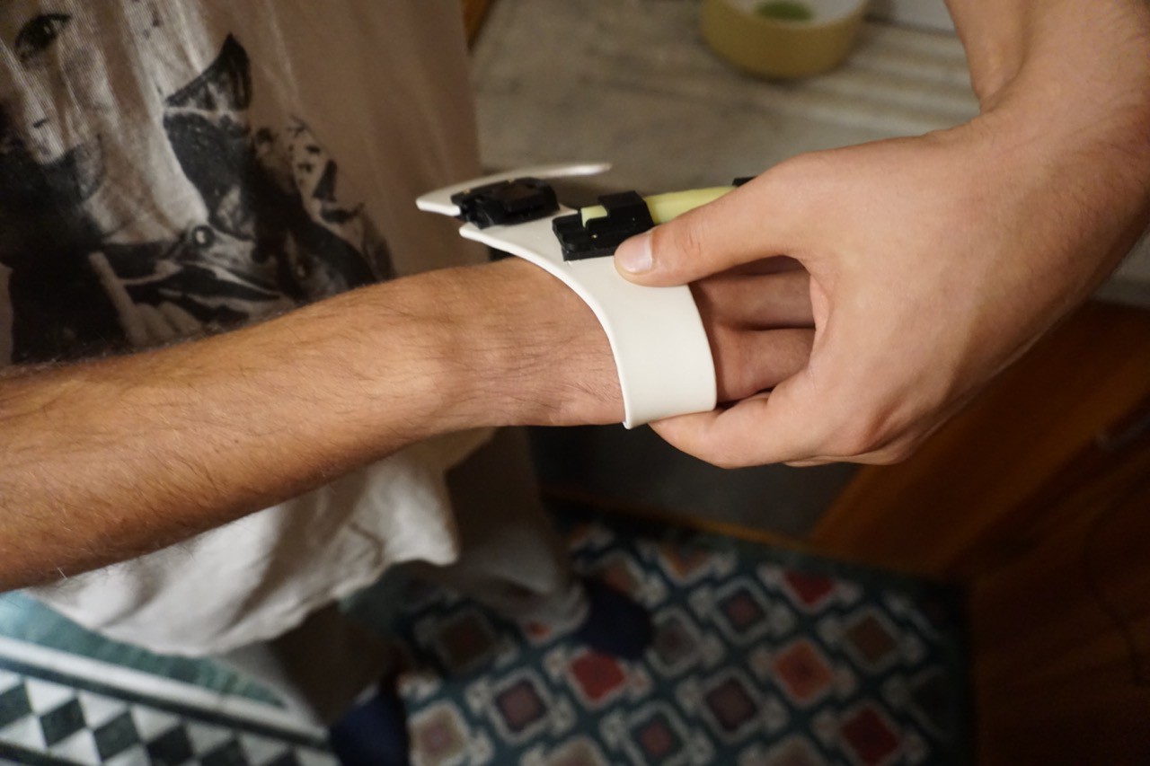
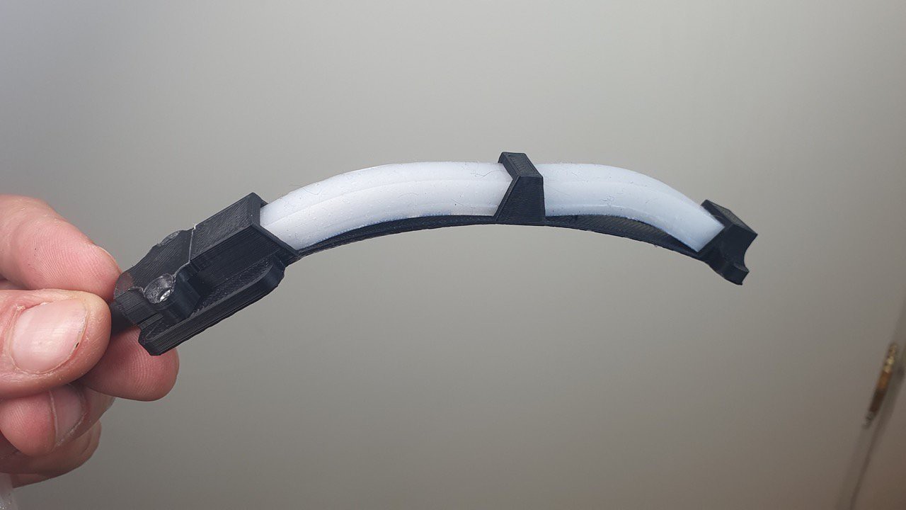
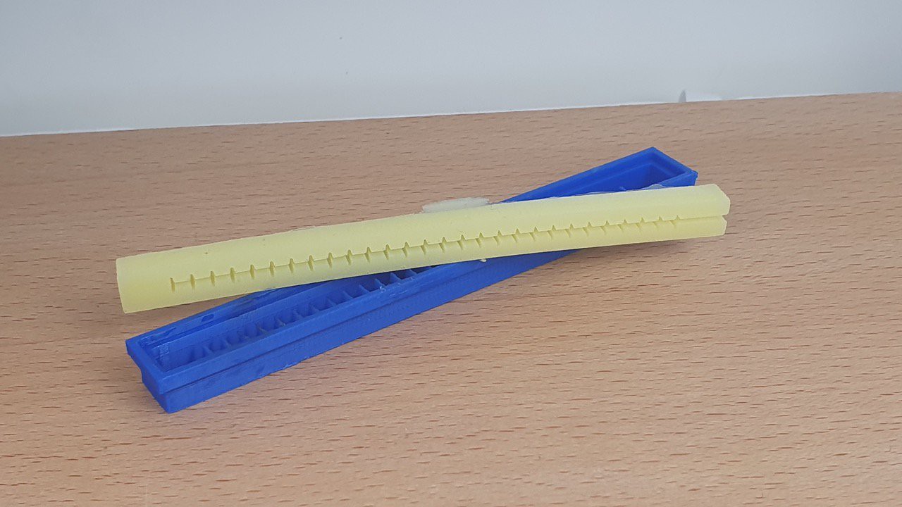
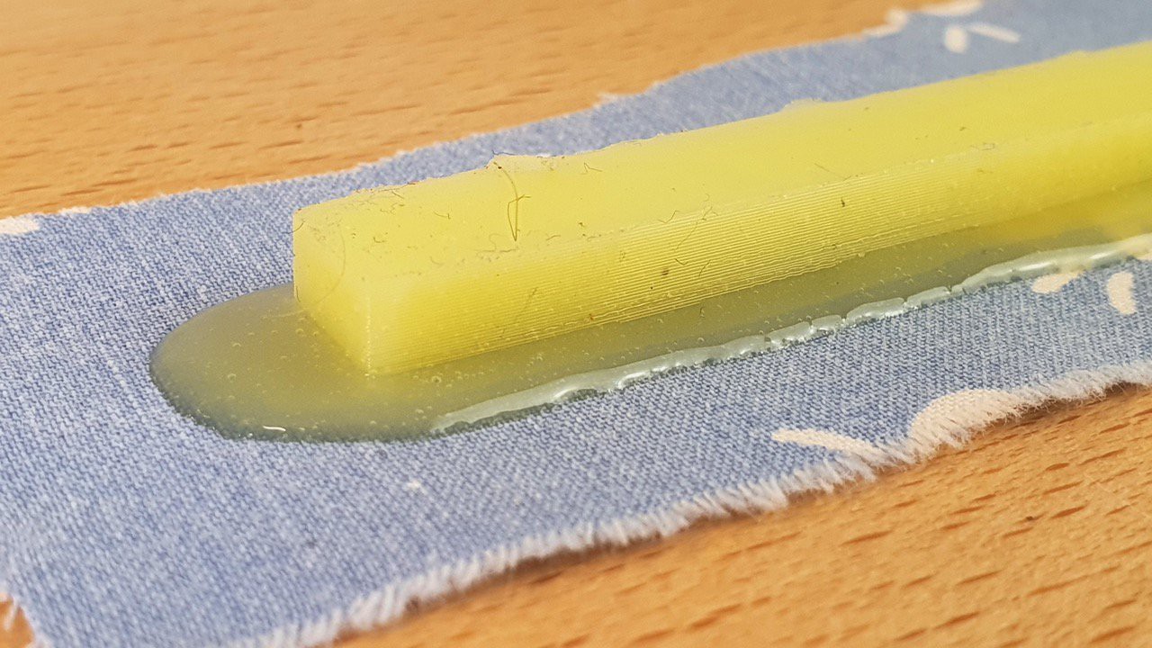
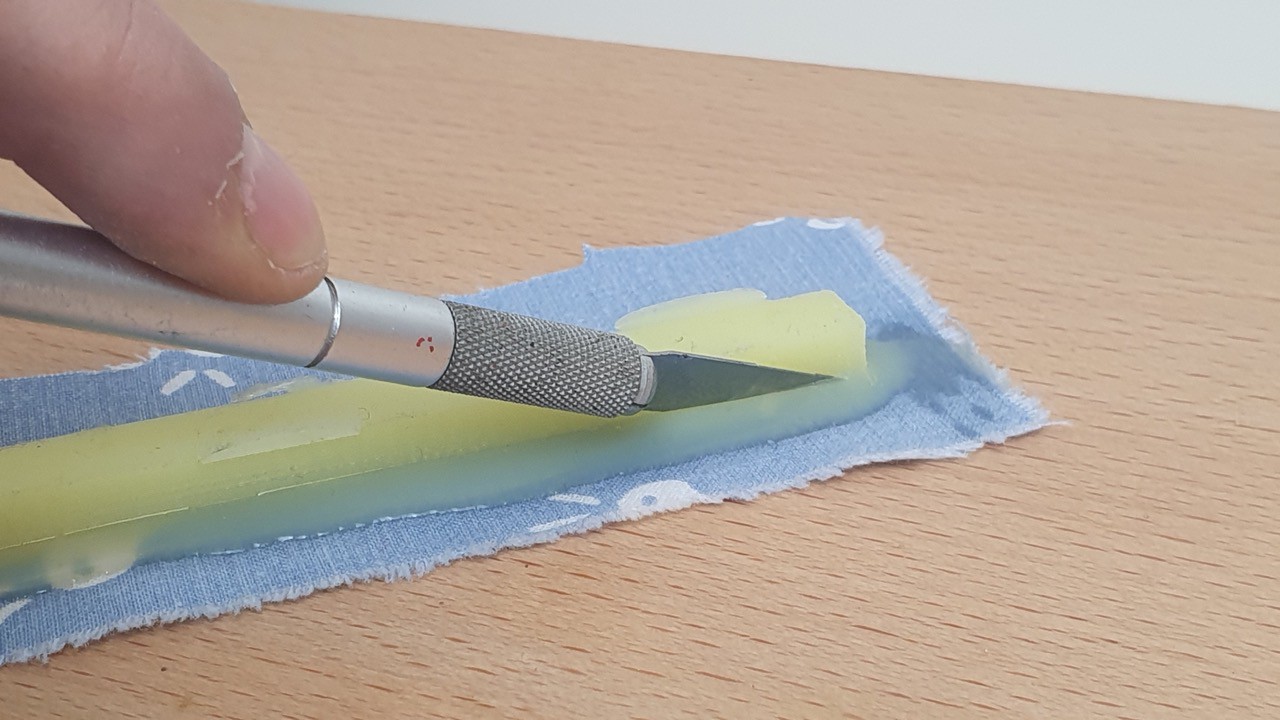
The original idea for the device was to create a prototype that seamlessly combined soft robots to complement the grasping motion, employing one inner tube to enable finger bending and a second to provide wrist support.


 oneohm
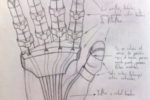
 Alvaro Villoslada
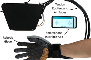
 New Dexterity
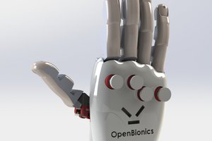
 OpenBionics