 Lithium ION
Water is the most important source of life for any creature existing in nature. From here the life begins on earth before many years ago. The existence of life depend on it and if we say drinking water then some care should be taken, like it should contain proper minerals, number of solid dissolved and free from any contamination. A pure water and distilled water both are two different things. Pure water is the term used for drinking water containing some ions, minerals and all but distilled water is de-ionized water and purest form nothing is present there.
We all know, Water do not have any taste but drinking water(from purifier) due to added minerals and other impurities have a little bitter taste in the same way water form borewell has a sweet taste, but distilled water do not have any taste this is all due to the impurities present there. These impurities are known as total number of dissolved solid (named as TDS) in water.
Measuring TDS:

We can measure the TDS of any water through a dedicated sensor which returns a value after sensing and then processed to an actual reading. To measure TDS a simple procedure is there, two electrode system is prepared with a voltage source attached to them. The movement of impurities and ions to these electrodes generate the signal and then measured.

But to make the system more reliable and to control the field applied to these electrode we can use the dedicated TDS sensor as mentioned above. It come with auto zeroing and offset calibration functions, you can calibrate the sensor by placing it into special type of buffer solution and entering the reading manually. But nowadays it comes fully calibrated out of the box.
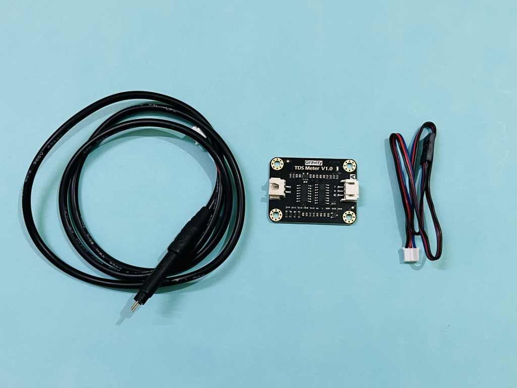
Gravity Analog TDS sensor:
This TDS sensor supports 3.3 ~ 5.5V wide voltage input, and 0 ~ 2.3V Analog voltage output, which makes it compatible with a 5V or 3.3V control system or board. The excitation source is an AC signal, which can effectively prevent the probe from polarization and prolong the life of the probe, meanwhile, increase the stability of the output signal. The TDS probe is waterproof, it can be immersed in water for a long-time measurement. An additional temperature sensor is required If temperature of water more than room temperature(25 degrees).

Features:
- Input Voltage: 3.3 ~ 5.5V
- Output Voltage: 0 ~ 2.3V
- Working Current: 3 ~ 6mA
- TDS Measurement Range: 0 ~ 1000ppm
- TDS Measurement Accuracy: ± 10% F.S. (25 ℃)
- Module Size: 42 * 32mm
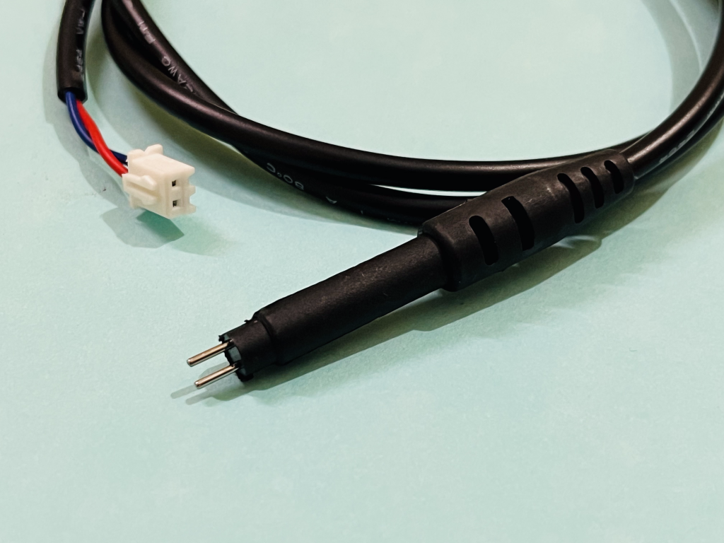
- Module Interface: PH2.0-3P
- Electrode Interface: XH2.54-2P
Components Required:
- Gravity TDS sensor
- Arduino NANO/UNO
- OLED display
- Wires and connectors
- Breadboard or Custom PCB Shield
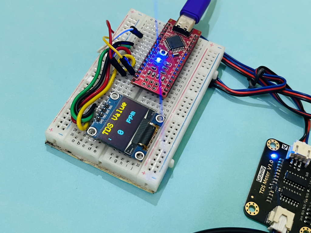
Circuit and Schematics:

Circuit is quite simple; TDS sensor gives analog reading which is measured by the Arduino and further results are calculated and displayed on the OLED screen. Connect the power to the sensor and sensor pin to the A1 of Arduino. Connect the OLED through the I2C interface, A4 to SDA and A5 to SCL. Here we are considering ideal conditions so the temperature sensor is not required. You can see other tutorials from here with temperature sensor and different microcontrollers.
Code:
you can download the libraries from the manage library section under the tools menu. This code is optimized for 12C OLED display (128x64).
#include <Wire.h>
#include <Adafruit_GFX.h>
#include <Adafruit_SSD1306.h>

#define OLED_RESET 1
Adafruit_SSD1306 display(128, 64, &Wire, OLED_RESET);

#define TdsSensorPin A1
#define VREF 5.0      // analog reference voltage(Volt) of the ADC
#define SCOUNT  30           // sum of sample point
int analogBuffer[SCOUNT];    // store the analog value in the array, read from ADC
int analogBufferTemp[SCOUNT];
int analogBufferIndex = 0,copyIndex = 0;
float averageVoltage = 0,tdsValue = 0,temperature = 25;

void setup()
{
    Serial.begin(115200);
    pinMode(TdsSensorPin,INPUT);
    Wire.begin();
    display.begin(SSD1306_SWITCHCAPVCC, 0x3C);
    display.clearDisplay();
}

void loop()
{
   static unsigned long analogSampleTimepoint = millis();
   if(millis()-analogSampleTimepoint > 40U)     //every 40 milliseconds,read the analog value from the ADC
   {
     analogSampleTimepoint = millis();
     analogBuffer[analogBufferIndex] = analogRead(TdsSensorPin);    //read the analog value and store into the buffer
     analogBufferIndex++;
     if(analogBufferIndex == SCOUNT)
         analogBufferIndex = 0;
   }
   static unsigned long printTimepoint = millis();
   if(millis()-printTimepoint > 800U)
   {
      printTimepoint = millis();
      for(copyIndex=0;copyIndex<SCOUNT;copyIndex++)
        analogBufferTemp[copyIndex]= analogBuffer[copyIndex];
      averageVoltage = getMedianNum(analogBufferTemp,SCOUNT) * (float)VREF / 1024.0; // read the analog value more stable by the median filtering algorithm, and convert to voltage value
      float compensationCoefficient=1.0+0.02*(temperature-25.0);    //temperature compensation formula: fFinalResult(25^C) = fFinalResult(current)/(1.0+0.02*(fTP-25.0));
      float compensationVolatge=averageVoltage/compensationCoefficient;  //temperature compensation
      tdsValue=(133.42*compensationVolatge*compensationVolatge*compensationVolatge - 255.86*compensationVolatge*compensationVolatge + 857.39*compensationVolatge)*0.5; //convert voltage value to tds value
      //Serial.print("voltage:");
      //Serial.print(averageVoltage,2);
      //Serial.print("V   ");
      Serial.print("TDS Value:");
      Serial.print(tdsValue,0);
      Serial.println("ppm");

      display.clearDisplay();
      display.setTextSize(2);
      display.setTextColor(WHITE);
      display.setCursor(0,0);
      display.print("TDS Value:");
      display.display();

      display.setTextSize(2);
      display.setTextColor(WHITE);
      display.setCursor(30,30);
      display.print(tdsValue,0);
      display.setCursor(80,28);
      display.print("ppm");
      display.display();


   }
}
int getMedianNum(int bArray[], int iFilterLen)
{
      int bTab[iFilterLen];
      for (byte i = 0; i<iFilterLen; i++)
      bTab[i] = bArray[i];
      int i, j, bTemp;
      for (j = 0; j < iFilterLen - 1; j++)
      {
      for (i = 0; i < iFilterLen - j - 1; i++)
          {
        if (bTab[i] > bTab[i + 1])
            {
        bTemp = bTab[i];
            bTab[i] = bTab[i + 1];
        bTab[i + 1] = bTemp;
         }
      }
      }
      if ((iFilterLen & 1) > 0)
    bTemp = bTab[(iFilterLen - 1) / 2];
      else
    bTemp = (bTab[iFilterLen / 2] + bTab[iFilterLen / 2 - 1]) / 2;
      return bTemp;
}
PCB and Shield:
Here I designed a universal shield for my Arduino based projects which has onboard Arduino NANO, headers, display, buzzer, power circuit and LED indicator. It will be easy to interface any sensor and module directly with Arduino. In this shield the PCB has onboard connection with 12C OLED, buzzer and light. Just change the pin number according it and we are ready to go. This code is fully compatible with this shield so you can download the Gerber file from here and order it from PCBWAY.
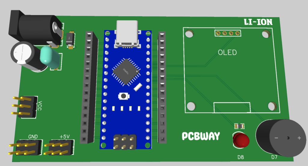
PCBWAY is China based PCB manufacturer provide prototype services of different kinds like PCB assembly, SMT assembly, Stencil service, 3d printing, FPC, flex PCB and Metal CNC. You can explore more from here 2layer PCB is starting from just $5. Register now on PCBWAY using this link and get free PCB coupons on first Sign-up.
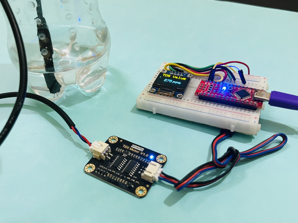
Working:

Just dip the needle of sensor wire in the liquid and you can see the readings in PPM on the screen as well on the serial monitor of Arduino IDE. The reading is always zero when the sensor is not immersed into water. You may get the stabilized readings within a minute after dipping sensor into water. The programming of Arduino is simple, connect the Arduino board, , select the board, choose the right COM port and hit upload. Make sure to download the proper driver if you have clone board.
Precautions:
The probe cannot be used in water above 55 degrees centigrade. The probe cannot be left too close to the edge of the container, otherwise, it will affect the reading.
The head and the cable of the probe are waterproof, but the connector and the signal transmitter board are not waterproof. Please be careful.