 DIY GUY Chris
Understanding The Circuit
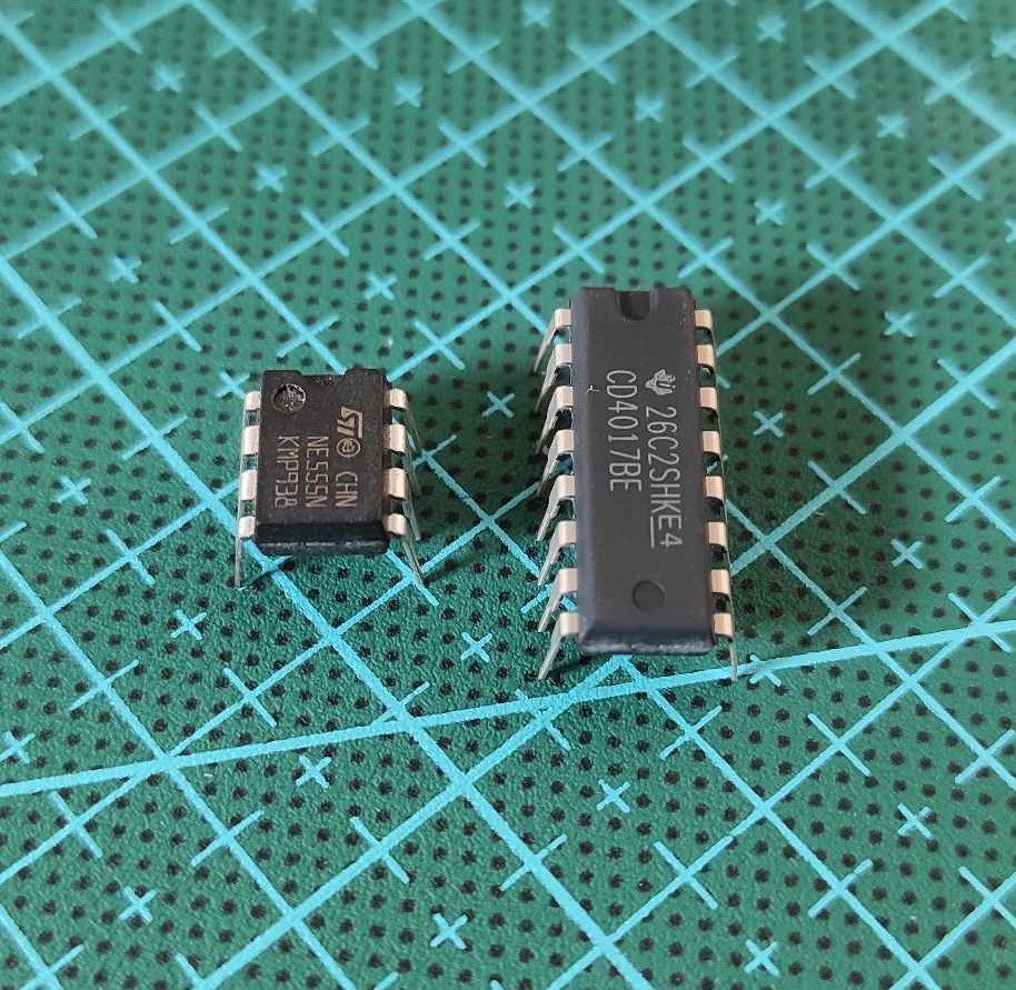
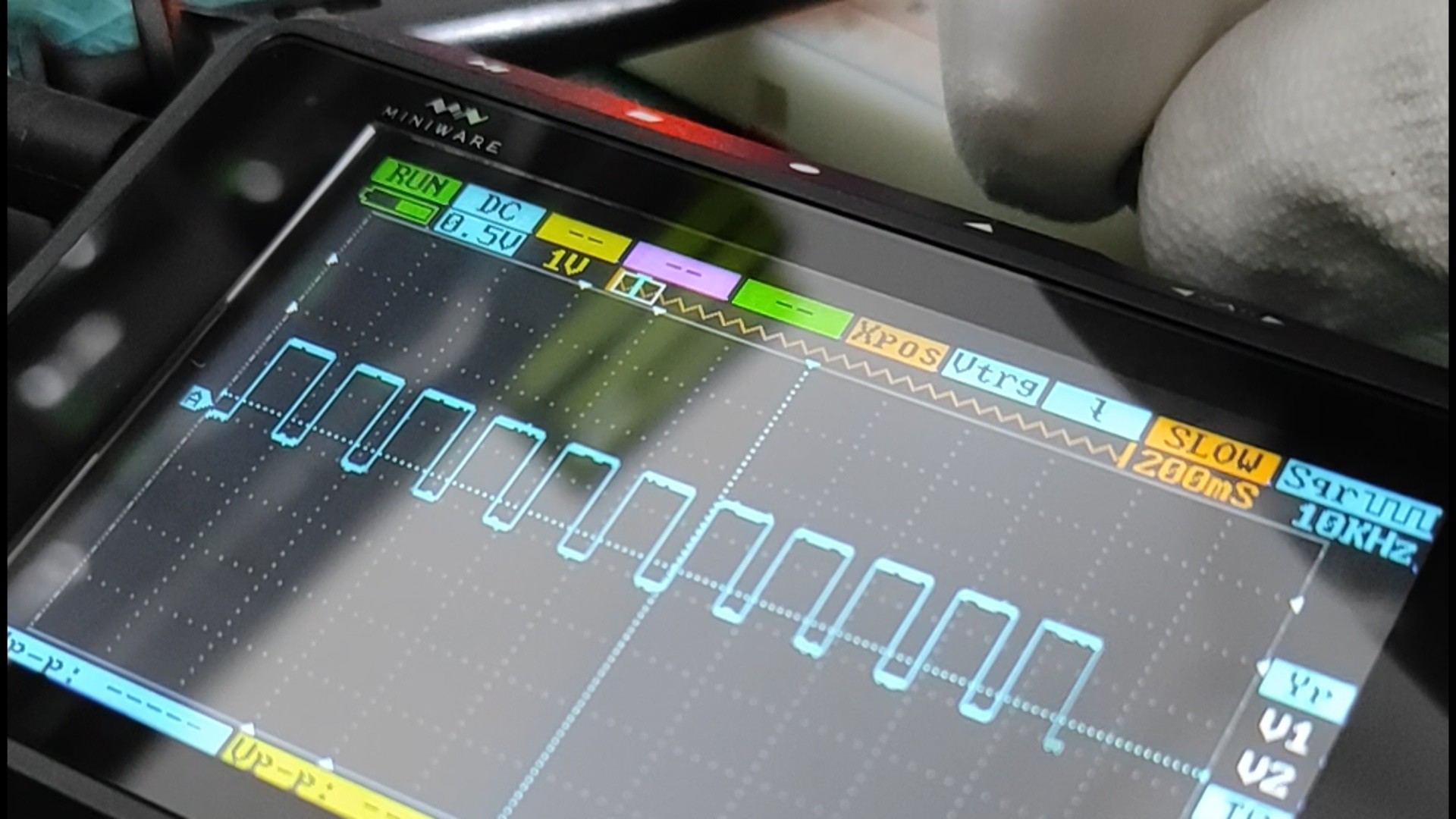
The LED Light Chaser circuit is based on two main components: the CD4017 Counter circuit and the NE555 Timer. The CD4017 Counter circuit scrolls bits at its outputs based on a signal's rising edges at its Clock pin. By producing a square wave signal at the clock pin using the NE555 Timer configured in Astable mode, we can control the scrolling speed of the bits, thus creating the LED chase animation.
Prototyping On A Breadboard
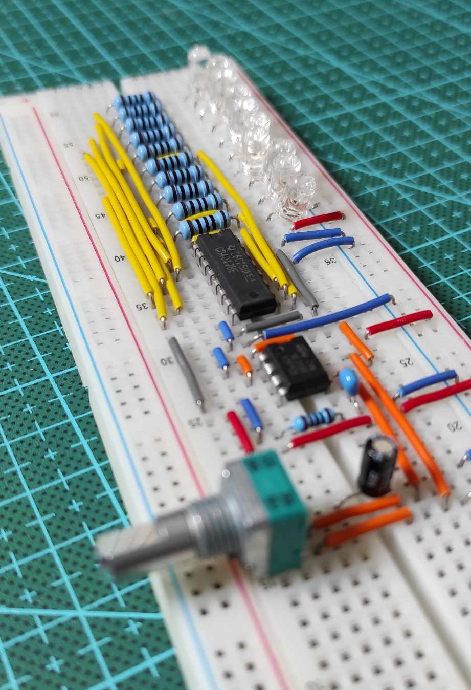
To test the connections and functionality of the circuit, start by assembling it on a breadboard. Connect the CD4017 Counter, NE555 Timer, and the necessary resistors and capacitors according to the circuit schematic.
Power the circuit using a 9V DC power source, and you'll see the LEDs light up, with the scrolling speed adjustable through a potentiometer.
Designing The PCB
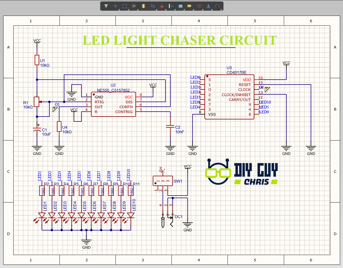
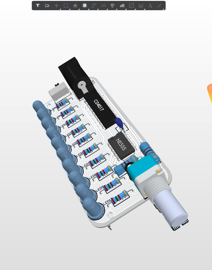
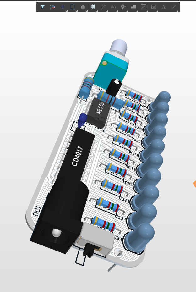
Once the circuit is working correctly on the breadboard, it's time to move on to the PCB design. Using a software tool like Altium, create the schematic of the circuit, placing the CD4017 Counter, NE555 Timer, LEDs, resistors, power connector, and slide switch accordingly. Ensure proper spacing and alignment of the LEDs and resistors to achieve a visually pleasing result.
Generate the Gerber files from your PCB design and submit them to a reliable PCB manufacturer, such as JLCPCB.
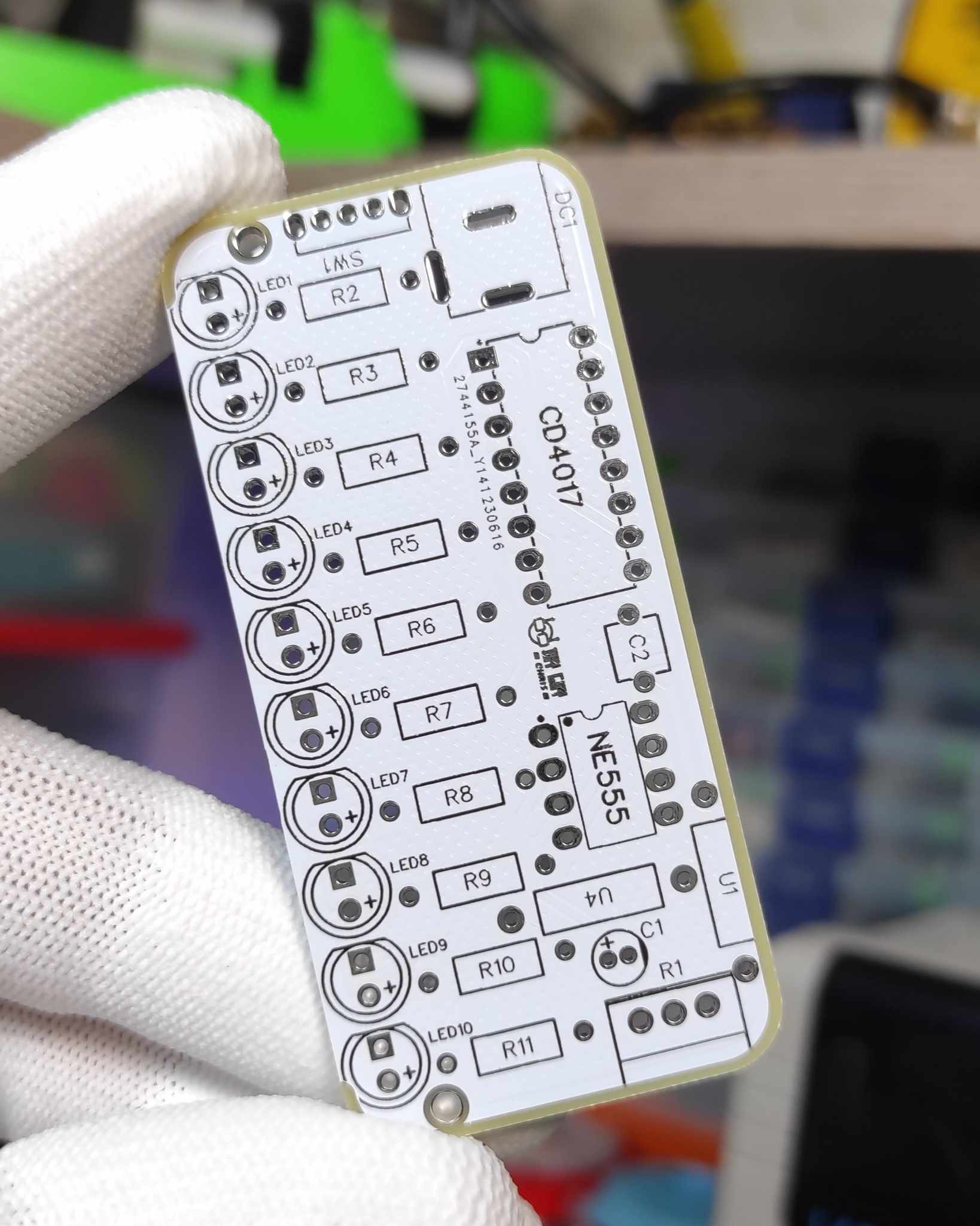
Choose the desired PCB specifications, quantity, and submit your order. In a few days, you'll receive the professionally manufactured PCBs ready for assembly.
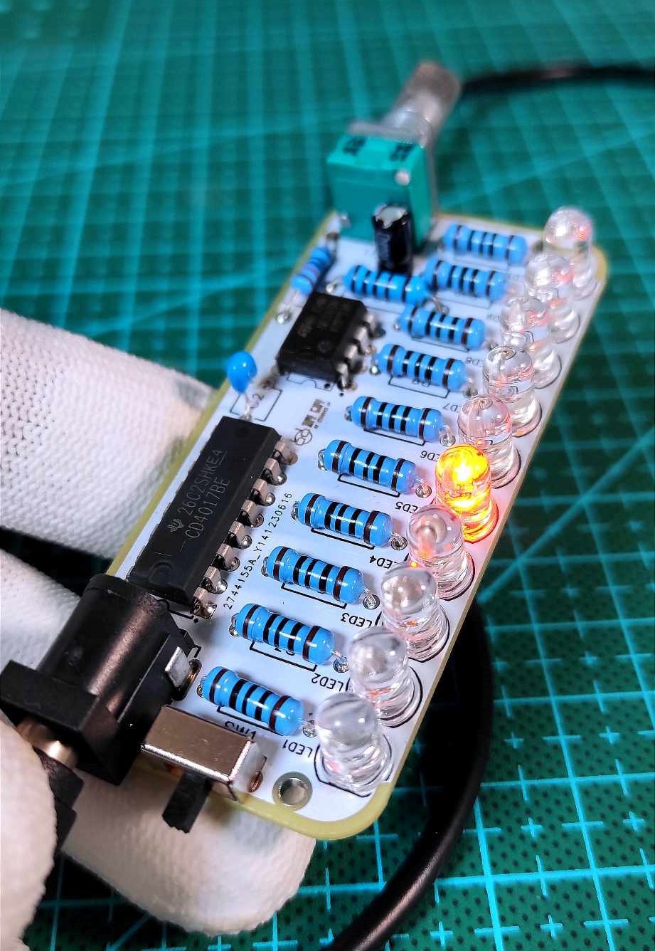
Soldering And Assembly
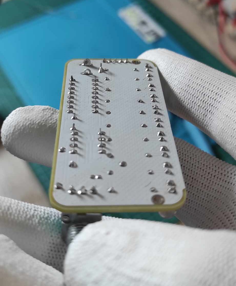
With the PCB in hand, it's time to solder the components onto the board. Use a soldering iron and solder core to attach the CD4017 Counter, NE555 Timer, LEDs, resistors, power connector, and slide switch to their respective pads on the PCB. Ensure proper solder joints and cleanliness.
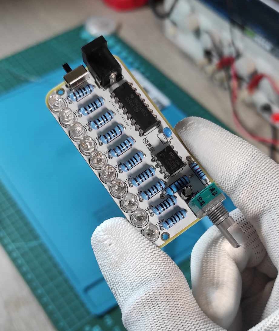
After soldering, clean the board using flux removal solvent to remove any residue.
Housing And Finishing Touches
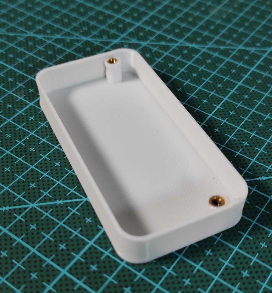
To give your circuit a professional and protected appearance, design a housing using a CAD software or create a simple enclosure.
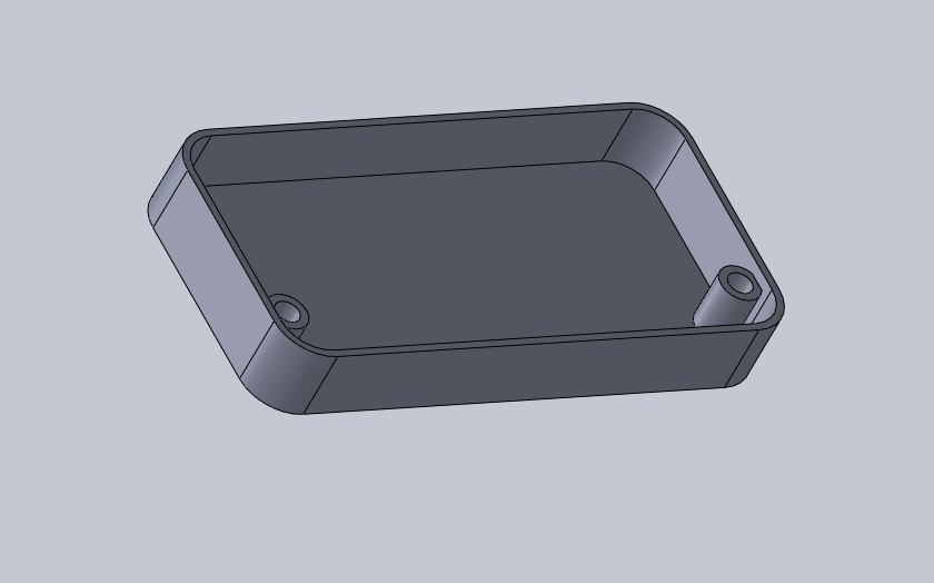
Utilize a 3D printer and PLA filament to bring your design to life. Attach the printed housing to the bottom side of the PCB using 2 mm threaded inserts or suitable fasteners.
Powering On And Enjoying The Animation
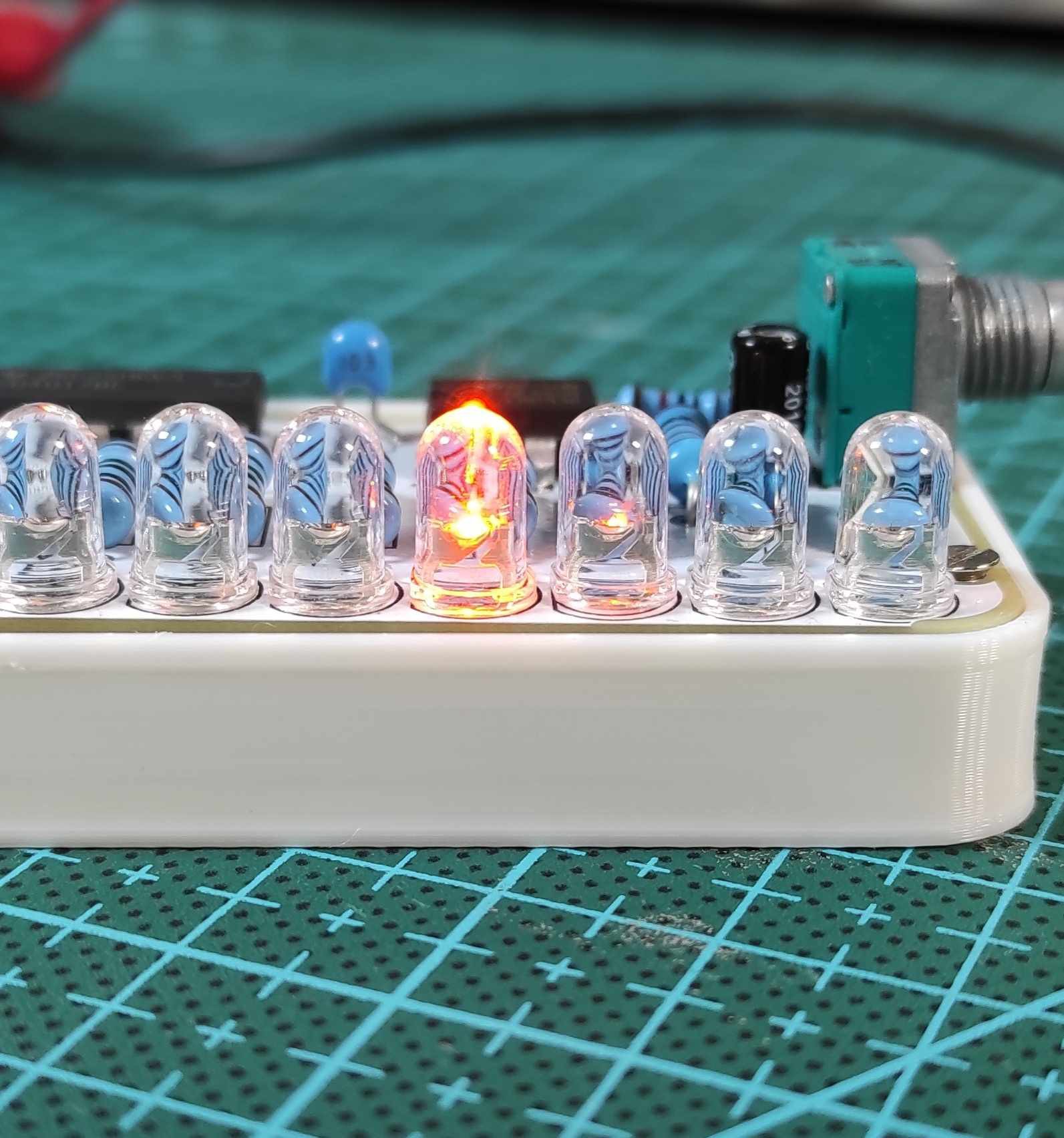
Once the circuit is fully assembled and enclosed, connect a 9V DC power source to the circuit using the slide switch. As you power it on, the LEDs will start producing the mesmerizing light chasing animation. Adjust the animation speed using the potentiometer to achieve your desired effect.
Congratulations! You have successfully built your own LED Light Chaser Circuit. This project offers a simple yet captivating way to incorporate mesmerizing light animations into your creative endeavors. Remember to explore and experiment with different designs and variations. Electronics can be a fascinating world, so keep honing your skills and enjoy the process. It was Chris, and I'll see you next time!
 YTURacing
 Discrete Electronics Guy
 Kelly Heaton