 Ludwin
1. Description of the device
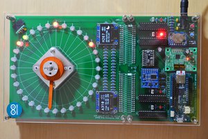
The Rotating Display device comprises two primary units: a power supply unit and a display board (figure 1). Both are circular in design, with a diameter of 120mm, similar to the dimensions of a standard Compact Disk. The display board is rotated by a CD motor. Energy is wirelessly transmitted from the power supply unit to the display board, eliminating the need for wired connections.
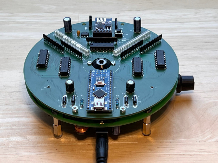
Figure 1: Rotating Display assembly. The lower PCB is the power supply with wireless power transmission, the upper PCB is the display board.
The display board is equipped with two rows of LEDs, each containing 20 LEDs. This makes a total of 40 LEDs available for image representation. The LED operations are controlled by an Arduino Nano, while an ESP-01s microcontroller generates the display content. The ESP-01s maintains a Wi-Fi connection to the internet for this purpose.
This internet connection allows the device to retrieve the time from a time server, ensuring time accuracy. It also allows for the acquisition of weather data. Device operation is managed through a web interface (figure 2), accessible from any web browser. The interface allows users to manage login credentials, upload image files to the display, and control image and configuration files through a file manager.
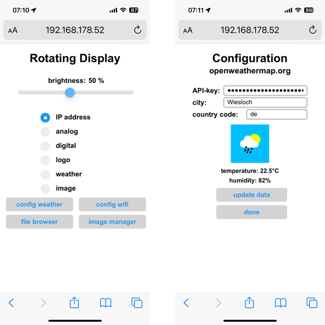
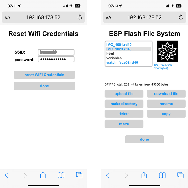
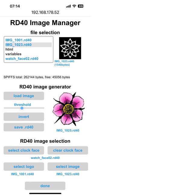
Figure 2: The web user interface allows for operating mode selection and device configuration.
There is a video on the rotating display available on youTube:
2. Operating modes
When switched on, the device tries to connect to a known wifi. If no valid wifi credentials are found, the unit will be configured as wifi access point. In this mode, a computer or mobile device can be connected, directly (SSID: RD40, no password).
Once the wifi connection has been established, the unit will display its IP address on the home page of the device (figure 3). Enter this address in your web browser. This will load the web user interface and will allow you to configure your local wifi.
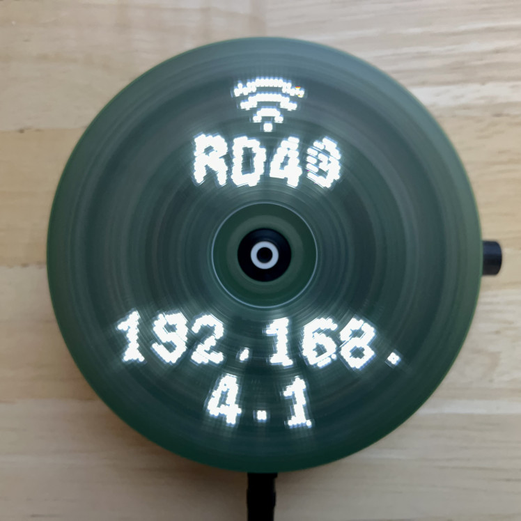
figure 3: home page.
There are several operating modes that display time and weather information (figure 4). The logo clock mode integrates a customizable image into the clock face. The image can be easily uploaded from the user interface. The same is true for the analog clock, which uses a customizable clock face in the background.
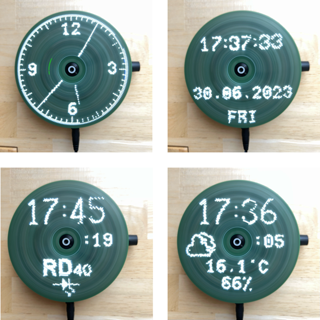 Figure 4: operating modes. Modes can be selected and configured through the web interface.
3. Mechanical design
The device consists of two assemblies: power supply and display. The power supply board is also the base plate, which can either be placed on a flat surface or hung on a wall. A standard CD motor is inserted through a recess in this board so that the CD tray above the board can accommodate the display assembly. The display board is fixed with two M2 screws. Furthermore, the base plate carries a potentiometer to control the motor speed as well as an on/off switch for the motor.
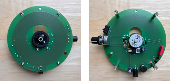
Figure 5: Power Supply Board with CD motor (middle), 12V power jack (lower side), and speed potentiometer
An important requirement for the display board is that the center of mass of the unit is exactly in the middle, on the axis of rotation of the motor. This is the only way to ensure smooth and vibration-free running of the display. To achieve this, the electronic components are arranged as symmetrically as possible to the vertical axis of symmetry in Figure 7. This initially ensures that the center of gravity lies on this vertical axis. However, since the components cannot be distributed symmetrically to the horizontal axis of symmetry, the center of gravity must be shifted to the center along this axis using balancing weights. For this purpose, two M2x6mm screws with two nuts each are placed to the right and left of the Arduino nano. The balancing result is very good, but can certainly be further optimized.
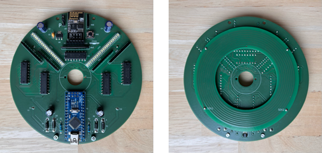
Figure 6: Display Board. ...
Read more »
 Frank
Frank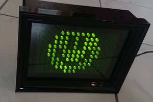
 joekutz
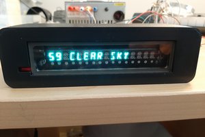
I am looking forward to your thoughts! Regards, Ludwin