 Sebastian
The mainboard features the main controller paired with an EEPROM, the resistor decades (precision resistors, signal relays) including two temperature sensors, relay drivers and signal conditioning for the two external digital inputs.
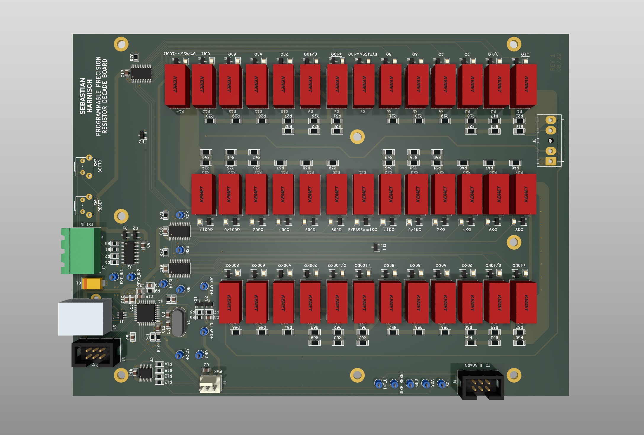
Rendering of the mainboard PCB generated with KiCad
Main controller
The main controller is a STM32G441KBT6 microcontroller (170MHz Cortex M4, 128kB Flash, 32kB RAM). The microcontroller features a USB 2.0 device peripheral.
The main controller contains the business logic required to control the relays and provide a user interface. It handles the processing of user user inputs, originating from either the mentioned user interface board, from SCPI messages sent over USB (virtual COM port) or from the external digital inputs.
Voltage, current and power limits are calculated based on a given resistance setpoint. Resistance setpoints are translated into switching sequences and sent to the relay drivers via SPI. Also, the main microcontroller manages all required calibration data and user settings.
An I2C-EEPROM (32kBits) is used to store different data related to the operation of the programmable resistor. Data integrity is validated with a CRC checksum. The data stored include the following:
- Calibration data (2W CAL, 4W CAL, CAL information)
- Instrument settings (e. g. Buzzer on/off)
- User settings (presets)
Relay driving circuit
To drive a total of 39 non-latching relays, three low voltage 16-bit constant current LED sink drivers are used. They essentially operate as a 48-bit shift register controlled over SPI by the main microcontroller.
Admittedly, the choice of a constant current LED driver as a relay driver is a bit odd. However, the operating conditions of the part allow for it and the part was chosen to drive the LED display on the UI Board, hence available. Care must be taken to select a constant current that is well above the minimum current to operate the relay properly.
A visual feedback for prototyping was achieved by adding a LED in series with every relay. As a side-effect the LED reduces any potential power dissipation in the constant current driver when operating a 12V relay on the +15V rail. That being said, this design might reduce the reliability of the unit: A defective LED would cause the relay to not operate. Not a big deal for my hobby applications, but if I had to build a unit for commercial use I would use a different driving circuit and not populate the LEDs. (I would use latching relays and therefore use a completely different drive circuit anyway. But that would be a discussion for another log.)
Temperature sensor
The mainboard features two KTY81-210 temperature sensors (PTC). The analog voltages of the voltage divider used are digitized with two of the 12-Bit ADC channels built into the main controller. The converted readings can be accessed through both the SCPI and the user interface. During calibration the temperature is recorded and saved to the EEPROM after completion.
External inputs
Two external, earth-referenced inputs can be used as either a simple digital input (that can be read through SCPI), a trigger input (positive, negative, either) or an inhibit signal (latching, live). Both are Schmitt-Trigger inputs and feature a resistor/diode protection circuit that allows for voltages exceeding the internal supply voltage of +3.3V.
Discussions
Become a Hackaday.io Member
Create an account to leave a comment. Already have an account? Log In.