 Guillermo Perez Guillen
In this section we will use ModusToolbox 3.0 which has enhanced support for multi-core project workflow. The release features dual-core device support, a new graphical tool for customer board support package (BSP) development, infrastructure support for ModusToolbox Packs and backend system improvements.

ModusToolbox 3.0
About ModusToolbox software you can find the documentation here: https://www.infineon.com/cms/en/design-support/tools/sdk/modustoolbox-software/
The PSoC™ 62S2 Pioneer Kit features the PSoC™ 62 MCU (CY8C624ABZI-S2D44): 150-MHz Arm Cortex-M4 and 100-MHz Arm Cortex-M0+ cores, 2MB of Flash, 1MB of SRAM, Secure Digital Host Controller (SDHC) supporting SD/SDIO/eMMC interfaces, programmable analog blocks, programmable digital blocks, Full-Speed USB, a serial memory interface, a PDM-PCM digital microphone interface, and industry-leading capacitive-sensing with CAPSENSE™.
Documentation: https://www.infineon.com/cms/en/product/evaluation-boards/cy8ckit-062s2-43012/
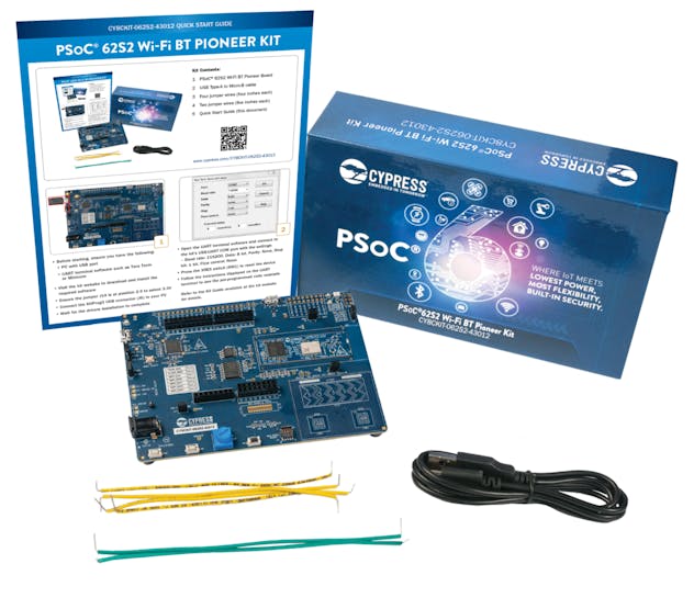
The PSoC™ 62S2 Pioneer Kit
CAPSENSE™ technology:
- Doesn't involve moving parts and will not wear out over time.
- Can be completely sealed to prevent moisture from seeping in.
- Doesn't require force to operate.
- Results in reduced BOM cost.
- Offers more flexibility in button shape, size, and graphical representation for your overall design.
Controlling Servo Motor With ModusToolbox
Servo motors are electromechanical devices that have the ability to control the angular position of their axis, their operation consists of receiving the information of the desired angle through the pulse width of a PWM signal to bring the axis to said position. According to the datasheet of the SG995 we have this graph that helps us to control the PWM signal and the duty cycle.

SG995 Datasheet
The position of the axis of the motor depends on the duty cycle of the signal. There are some standard calculations for degree rotation. If the PWM signal is high for 0.5ms in a single cycle, the axis moves to zero degrees. To rotate the motor axis to 90 degrees, the signal should be high for 1.5ms. Similarly, a 2.5ms ON-time signal leads to 180-degree axial position. In this way, we can measure and control our servo motor to desired degrees.

Correlation between the duty cycle with the angle of the servo
According to the example "HAL PWM square wave" we see that it uses a library to control the PWM signal and the duty cycle. I just have to insert the values of the frequency and the duty cycle percentage. By interpolation, we can calculate: if 20 ms is 100% duty cycle, then 0.5 ms is 2.5% duty cycle. Similary 1.5 ms is 7.5% duty cycle, and 2.5 ms is 12.5% duty cycle.
I experimented with this data, and the only value I adjusted was the 0° angle at 3% duty cycle, because the servo was vibrating and making noise at 2.5%. The final data is shown below:

Correlation of the values with the percentage of the duty cycle
Fitting a data set to a trend line using excel
The data between the angle and the duty cycle percentage are not linear, so I found a method to get a formula with excel.
- First we make a scatterplot using the data from the table above. The x value corresponds to the angle, and the y value corresponds to the duty cycle percentage.
- Then, on a point of the graph we click with the right mouse button and select add trendline.
- In the drop down menu I chose polynomial trendline option with degree 2.
- Finally, through the displayed menu I ask Excel to display equation on chart. Below I show you the final result.

Obtaining the formula to calculate the percentage of the duty cycle (y), if I have the angle that the servo rotates (x)

This is the formula that I will use in the next sections to move each servo of the robotic arm.
Discussions
Become a Hackaday.io Member
Create an account to leave a comment. Already have an account? Log In.