 Guillermo Perez Guillen
Arduino Version
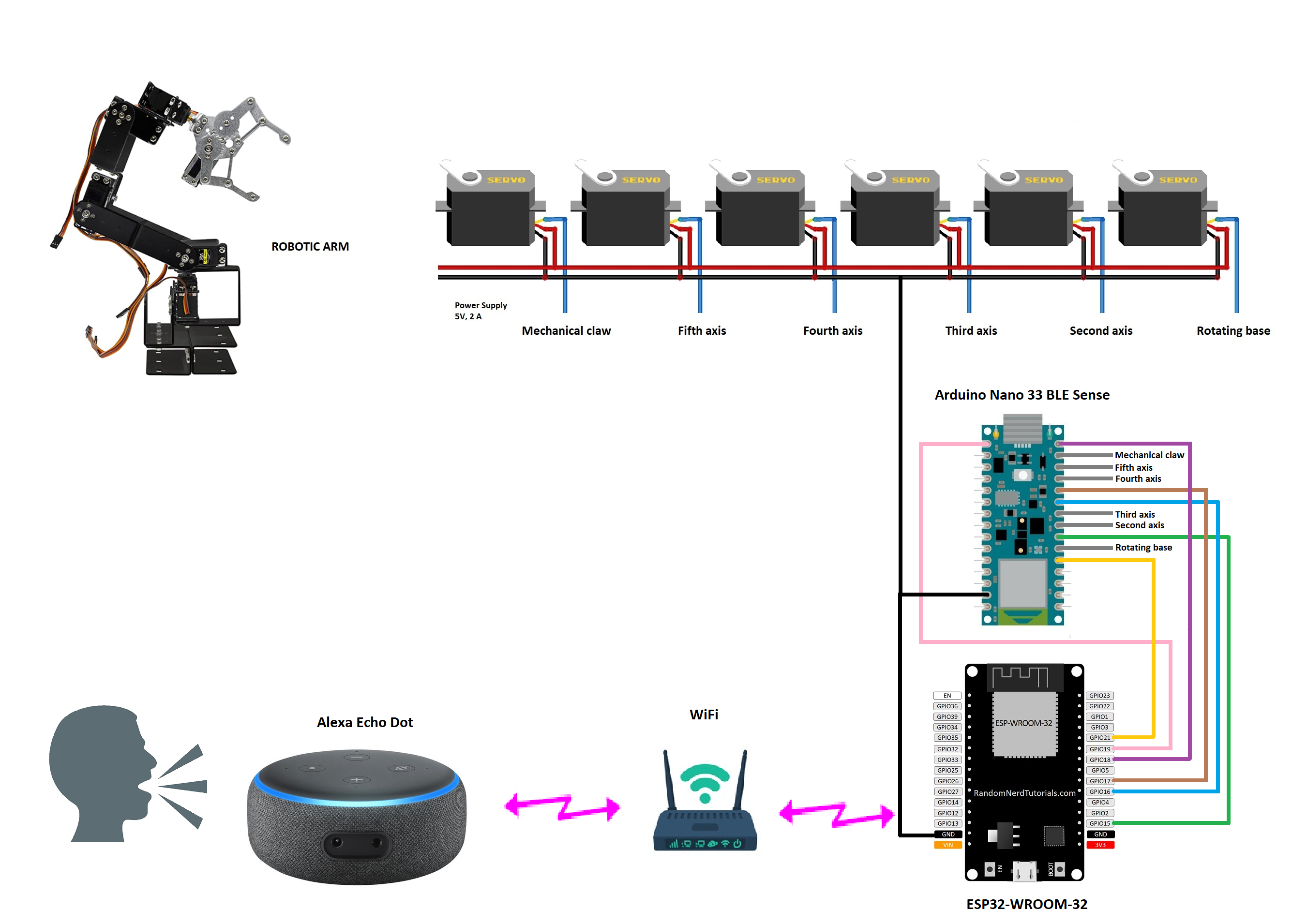
- This project was a good experience as I used a free tool to control my robot arm with the Alexa Echo Dot device. Also I can increase the voice commands as far as the memory capacity of the processor allows. As you can see, the clamp has large dimensions, so it can hold much larger objects, or even hold them in the right place so that we can work comfortably.
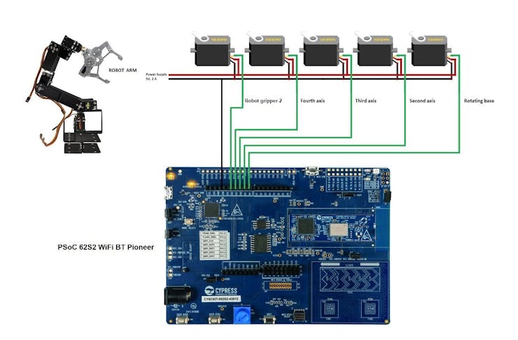
Infineon Version
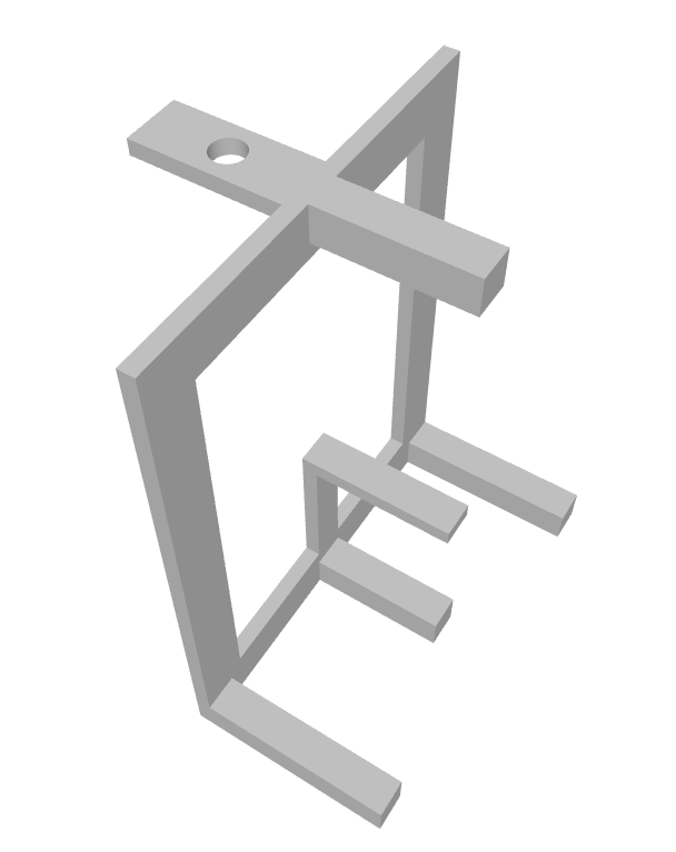
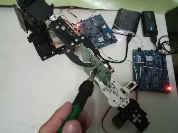
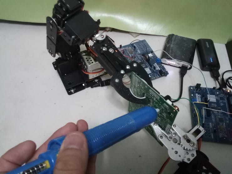
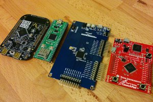
- In this version of the robotic arm I tried something different. I used capsense technology buttons and sliders to hold PCB boards in my electronics workshop. I had the idea of holding PCB boards to solder and unsolder electronic components.
Sorting Objects
- In this project the idea is to combine the robotic arm with a 3D magnetic sensor to classify objects. Here I took time to invent the piece that holds the magnetic sensor. The operating mechanism is easy since the moving object rotates the magnetic sensor knob and this activates the robotic arm.
Below you can see a video showing how the prototype works.


 Mike Szczys
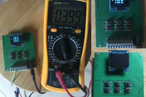
 RT-Thread IoT OS
 [ E C C 0 ]
 RoGeorge
This idea helps to solve the challenge of the "Gearing Up" category, since it uses the robot gripper jaws in a novel way in an electronic workshop. It also teaches us two opensource versions for different users preferences: Arduino version with AI and Infineon version with capsense buttons.