 mkdxdx
There were couple points in time when I was in need of:
- a purpose for a SBC i've had laying around;
- a platform to experiment with general purpose embedded system that ran Linux;
- a case to dip my toes into elaborate electronic box design in CAD of choice with further employment of FDM 3D printing to make this design real;
- a backup computer of sorts, not necessarily a performant one, but with easy access to it's detachable constituents;
- a proper scratch to an itch of an intense desire to have a cyberdeck which materialized after you know who did his rizz; add a few rounds of scrolling through existing and fictional designs related to the matter also;
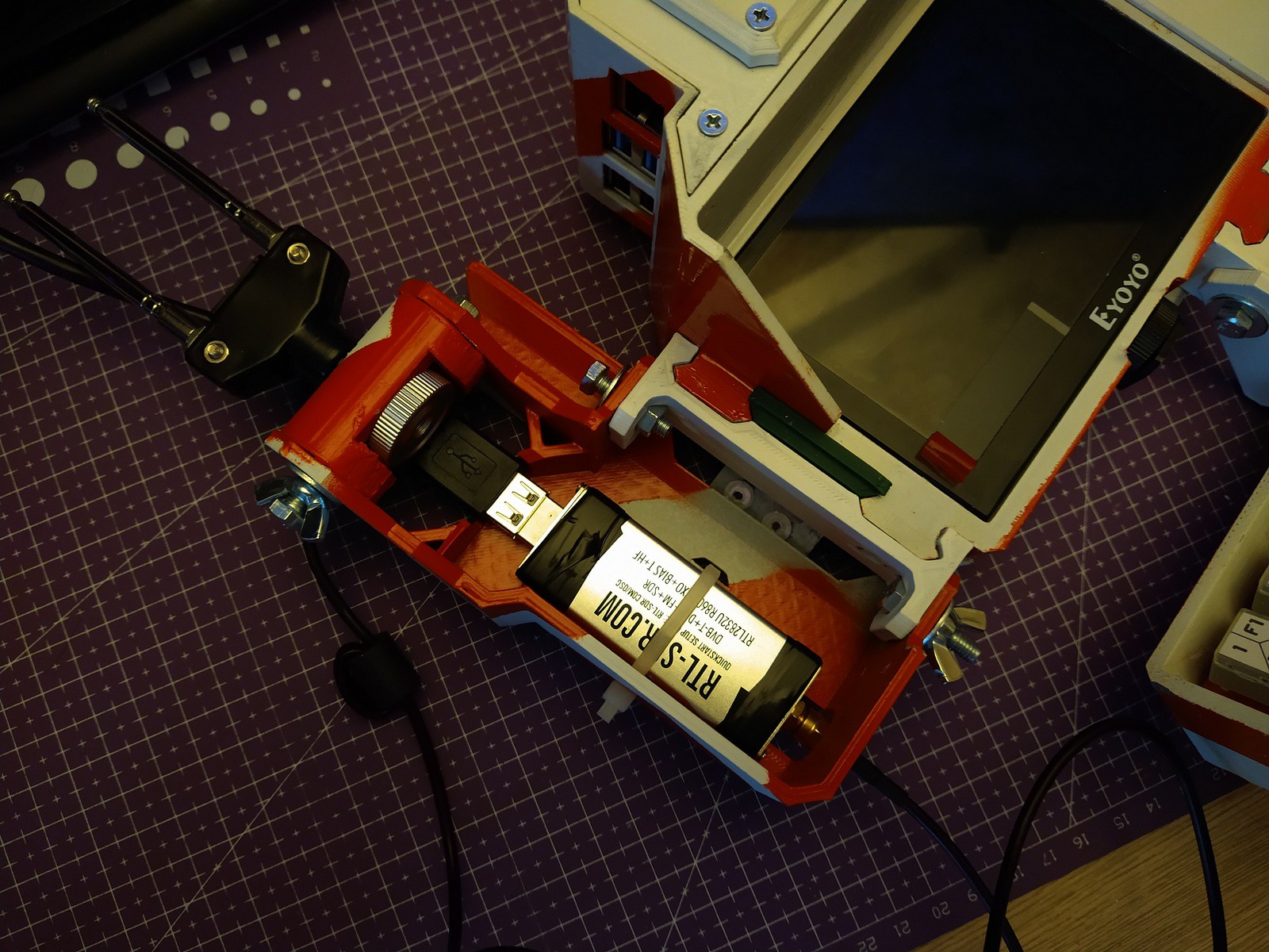
- having a semblance of a doomsday communication device due to recent events (especially country-wide blackout periods); dunno who I would talk to while inhabiting this kind of dystopia, but my wishful thinking makes me hope that I will be able to set up a few LoRa nodes to talk to my buddies after comms go up in smoke and before electronic warfrare starts to cover residence areas.
Initially I was trying to cram everything into a CNC control panel which was bought in a local flea market, but eventually I've fired up FreeCAD and after a year and some (primary parts were not designed during the 2023 Cyberdeck contest, but as you may know, the hardest project part starts after 85% of progress - and so few of those % were rushed after contest was announced) ta-da - Zvychai One (case logo natively spells "ЗВИЧАЙ 1") came to fruition, featuring:
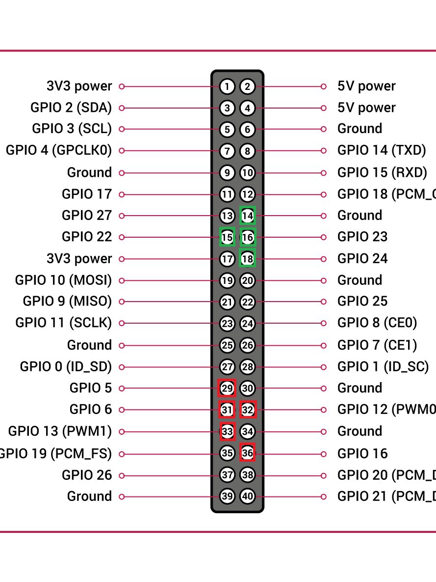
- 8G Raspberry Pi 4;
- 5" Eyoyo TFT display;
- 40% KPRepublic BM43A keyboard powered by QMK;
- Geekworm X708 v2.0 UPS HAT with double 18650 battery holder as a primary power management system;
- design that is self-sufficient in base configuration and yet aims to tick a few boxes to be extendable;
- clicky connector lid action thanks to some magnets from Aliexpress.
Primary features should be pretty self-explanatory - this is a RPi based machine with some autonomous capabilitues.
The "extendable" part is what i would like to drive the project further, namely:
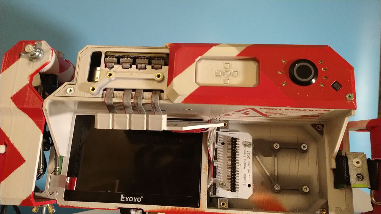
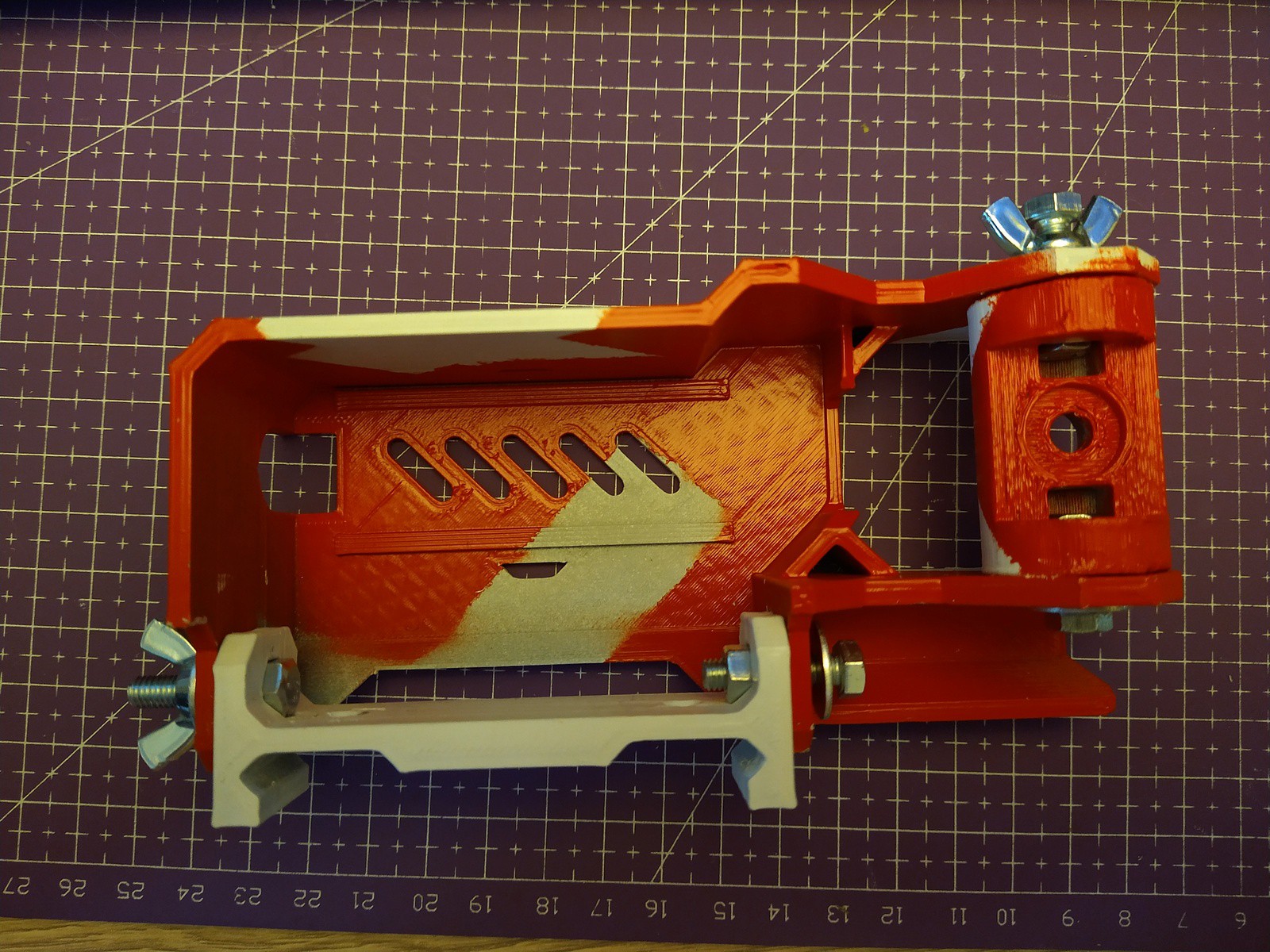
- 3 pairs of "Picattiny rail" like moutning points for different heavy-duty attachments (currently carrying handle, detachable strap holders, ethernet switch and SDR receiver caddy with antenna attachments are available; keyboard carrier is also on this rail);
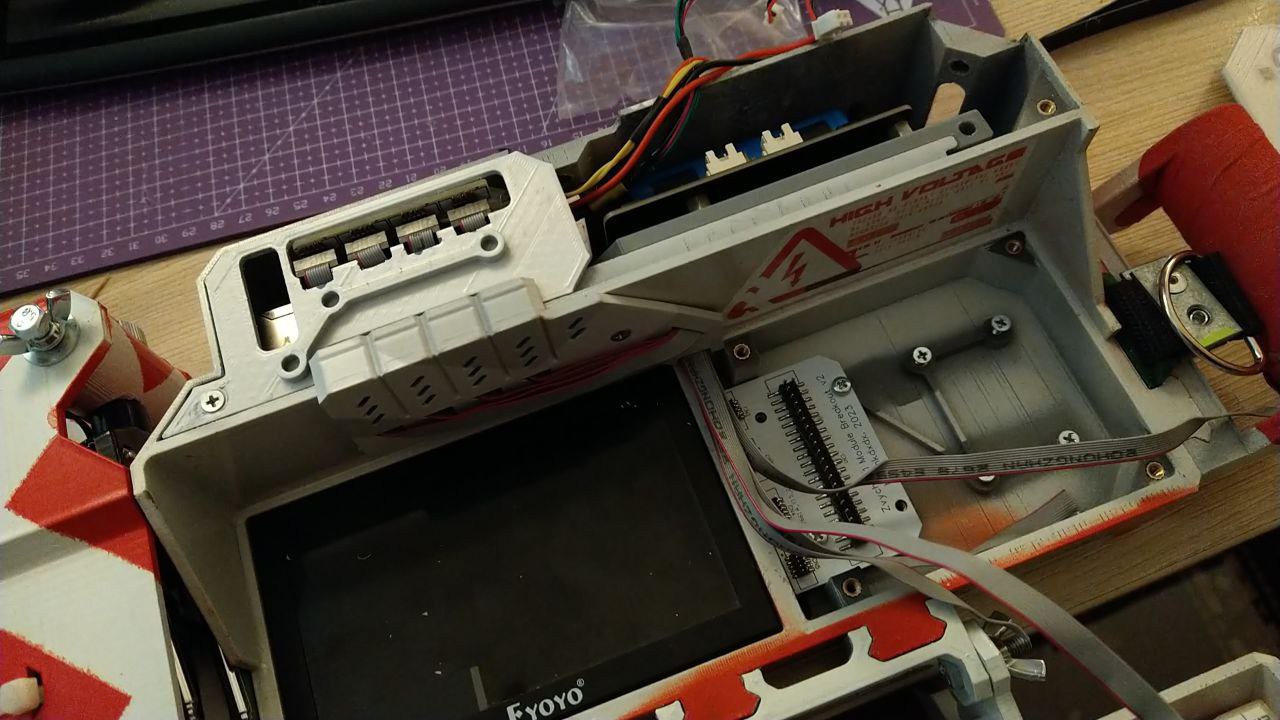
- 1 module well (to the right of the screen) which can house.. whatever you can fit there - a devboard, a PCB, a RGB macro input panel, beefy power source etc;
- 2 smaller module openings (top left and right), which probably can house sensor boards, cameras, small displays etc.;
- 3 auxiliary openings on primary case and keyboard carrier - initially to be used for wiring between the two and/or installing a USB hub or additional battery inside the keeb carrier, but they are vacant for now and covered with bolted on lids;
- 1/4" tripod mount to, well, put it on a tripod; with adapters it probably can be used to mount a GoPro or a light source, you name it;
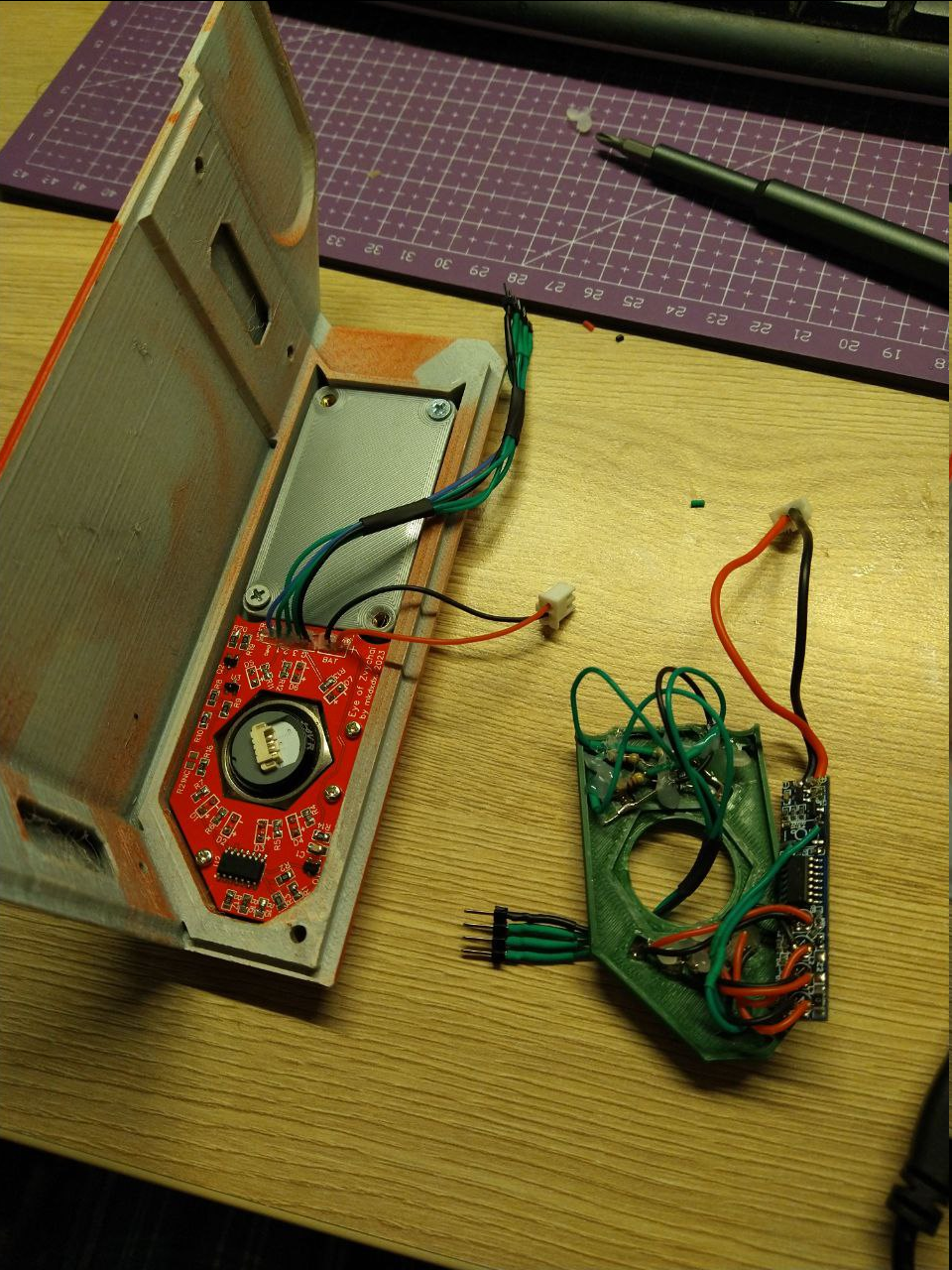
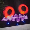
- 3 LEDs near charge level indicator resemble a "notification panel" with user defined function;
- the "spine" under the back cover also has several points where heat-set nuts can be installed and then something can be bolted to them;
And as a bit of closing trivia - "Zvychai" can be roughly translated as "tradition"/"custom" from my native language. Name is partially influenced by how domestic electronic industry of the past named household appliances it was producing (just look up names of TV sets/casette players in USSR).
Despite naming it "One", it is actually a 4th iteration of the design and that is what reflected as "v4" in design files.
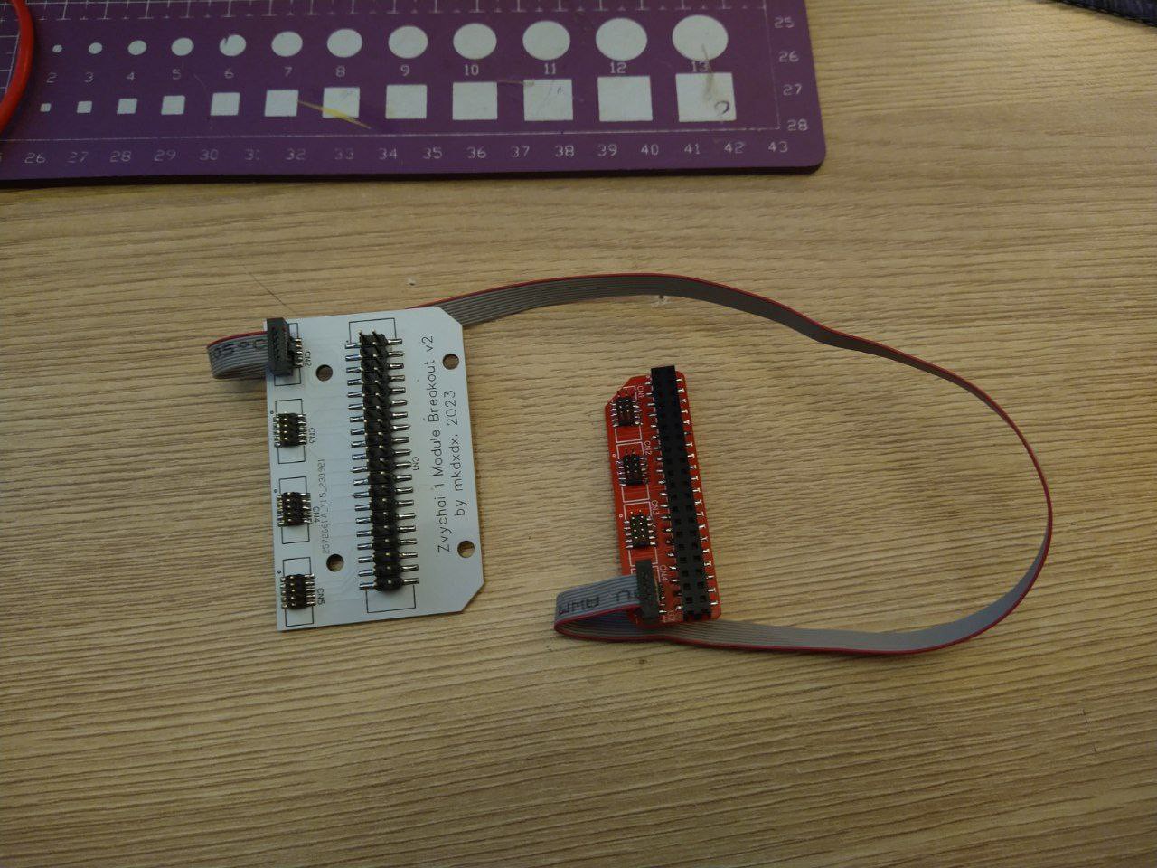


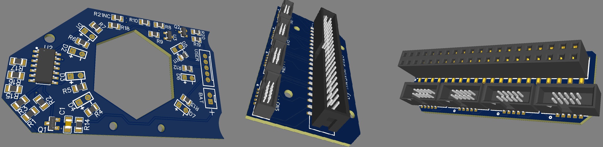
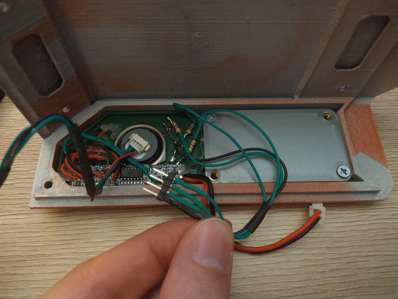
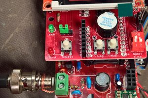
 The only problem with it is that i have used PH2.0 connectors to interface the board with everything, and even they have high enough profile to push against battery caddy and prevent top cover from being flush when assembled.
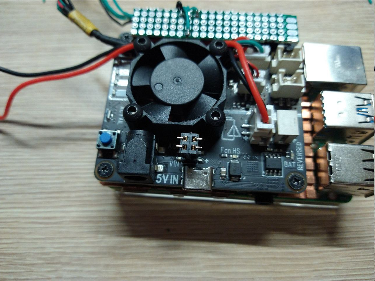
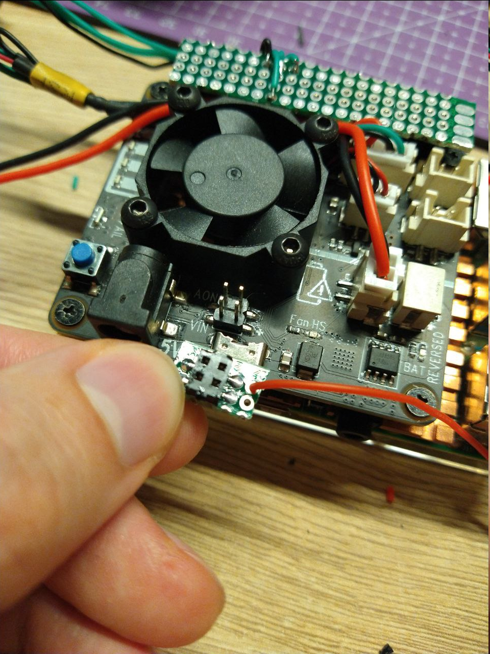
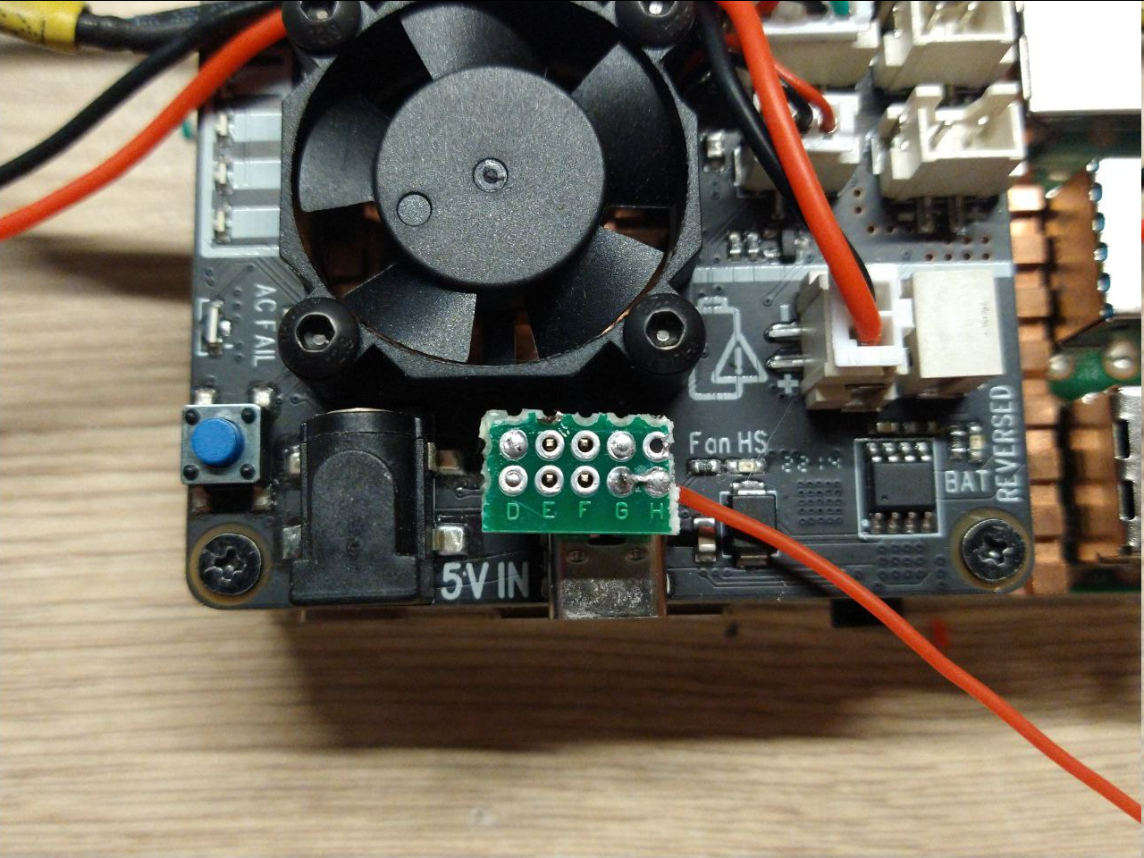 One nice thing about this little connector board is that it clamps display power connector under it so it won't fly around when you are working with the board.
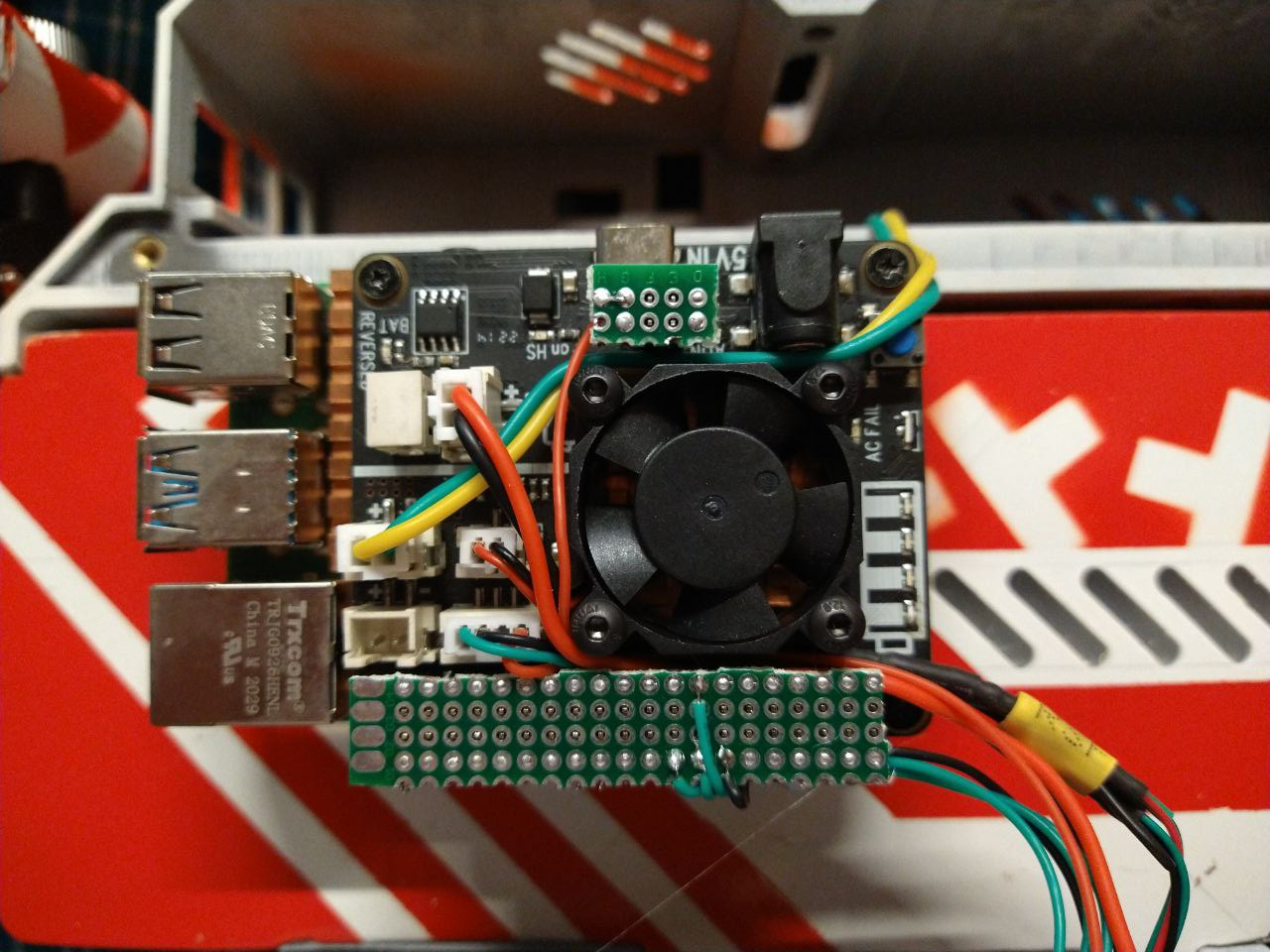 There ain't much new to demonstrate though, i've shown how indication panel works before but here is a more marketing friendly action which shows how new leds flash and how board reacts to charger connected.
 And free advice for the most patient readers: please have enough sleep especially when actively working on a project. Assembling the board was not really hard, however when parts arrived, it's either me or the seller who swapped N-mosfet reel with P-mosfet reel, which took me 2 hours at 3am to figure out after the fact that i've soldered both onto the board (basically means that both of them are open when power is applied, which was not the intended effect).


 Jon Kunkee
 gilphilbert
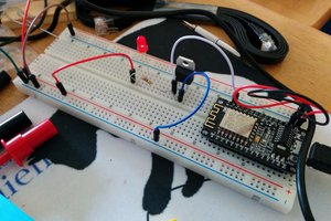
 WJCarpenter
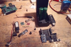
 Arya
Arya
dude it's look like an amazing gaming console which can play games like https://mini-militia.com/mini-militia-for-pc/ thanks for sharing.