While browsing eBay the other day I noticed that the used price of NI's (National Instruments) 1st generation PXIe-5644R VST (Vector Signal Transceiver) plummeted and can be bought from some sellers for a few hundred USD.
It could be used as a very capable SDR (Software Defined Radio) platform or as general use instrumentation in the home lab.
The low price is due to the instrument being a add-in card type module, instead of a standalone bench unit. I'll attempt to create a hobbyist wallet compatible hardware solution to integrate the device into an ordinary desktop PC.
Details
Quick Q&A:
What is this device?
The NI PXIe-5644R VST is a 65MHz-6GHz RF signal analyzer + generator + FPGA instrument module with 80MHz instantaneous bandwidth. If you're thinking USRP you're not too far, but it is a professional, calibrated instrument mainly targeted for mass production automated test of RF electronics.
The adapter hardware presented here could work with other PXIe instruments too, but the 5644 VST's current used price made the whole project worth, so I'm focusing on that.
What is PXIe?
PXI Express
For the long version use google, it will give you many detailed articles
TLDR: It's industrial PCI Express. The signaling is (mostly) the same, but in a very different form factor. The gist of this project is to adapt that form factor to a regular desktop PC... for questionable gainz and lolz.
How does this work in its natural habitat?
Normally, in order to make such an instrument work you need 3 things.
The instrument itself
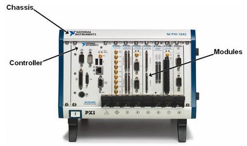
The enclosure, called a "chassis", that provides mechanical mounting, power, cooling and the PXI bus connections. Think of it as your regular PC case plus the part of the motherboard where the PCIe slots are.
An embedded controller that looks very much like an instrument module, but using prior analogy it's the rest of the motherboard and the CPU. Alternatively a remote controller can be used to connect the chassis to a desktop PC through some variation of PCIe. I am not aware of any embedded controllers up to date being built on anything else than x86. It runs Windows, real-time Linux or whatever.
The problem is that these parts also cost a non insignificant amount of money, even used. Remote controllers are rare to come by, embedded controllers are expensive and can severely limit performance. You can't swap the CPU in these. Plus if you buy all this where's the fun? So, again, let's just take the instrument module and cram that sucker into your regular (*) old desktop PC.
Is there software for this thing?
Yes, actually software support, as far as obscure industrial things go, is pretty good and accessible. The Windows driver suite contains a capable spectrum analyzer and a signal generator application. There are APIs for C++/C#.NET and LabVIEW. It's reasonably easy to use and well documented.
Is it worth?
As much as I'd like to say yes, probably not. I have worked with these instruments before and took a liking to them. I'm doing this for fun and learning. That being said I'm aiming for a financially feasible end result that's cheaper to DIY than to buy the proper parts or to get any other comparable instrument or software radio, but we'll see what comes out of it.
Whats the current status?
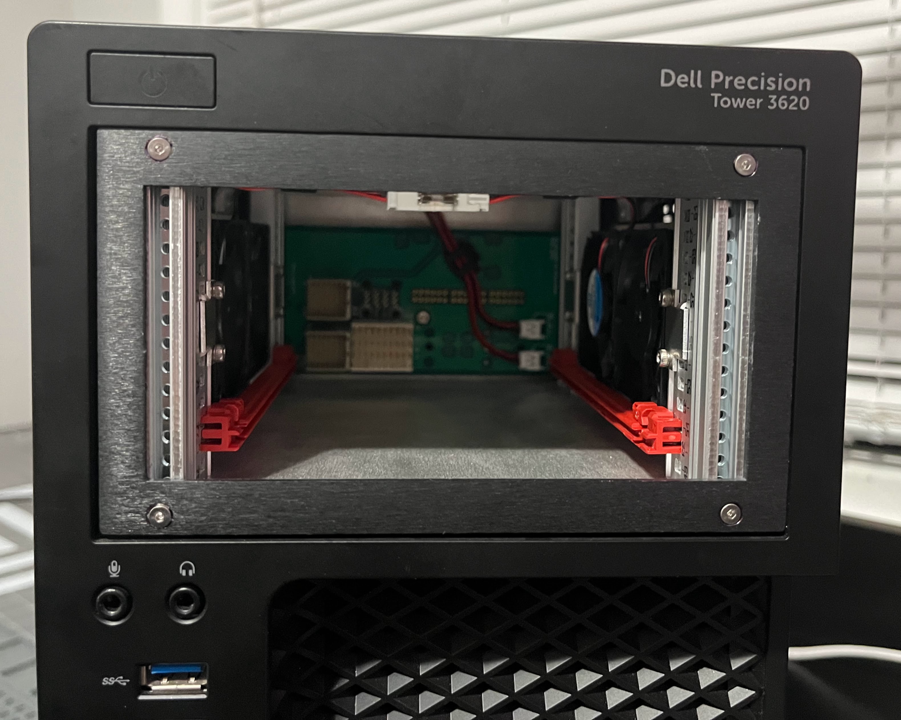
Rev A. done, it works fine in a refurbished Dell workstation. I don't like the fact it requires quite extensive mods to the case. (Cutting multiple openings for side to side airflow) The tiny fans are also loud. For this reason I decided to ditch the original idea to fit this into a standard double 5.25" drive bay and instead building the next version for a specific PC case. I had to make this sacrifice of universality.
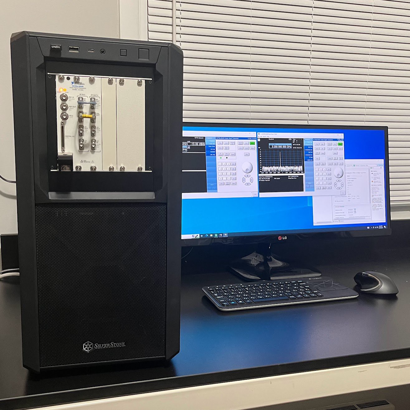
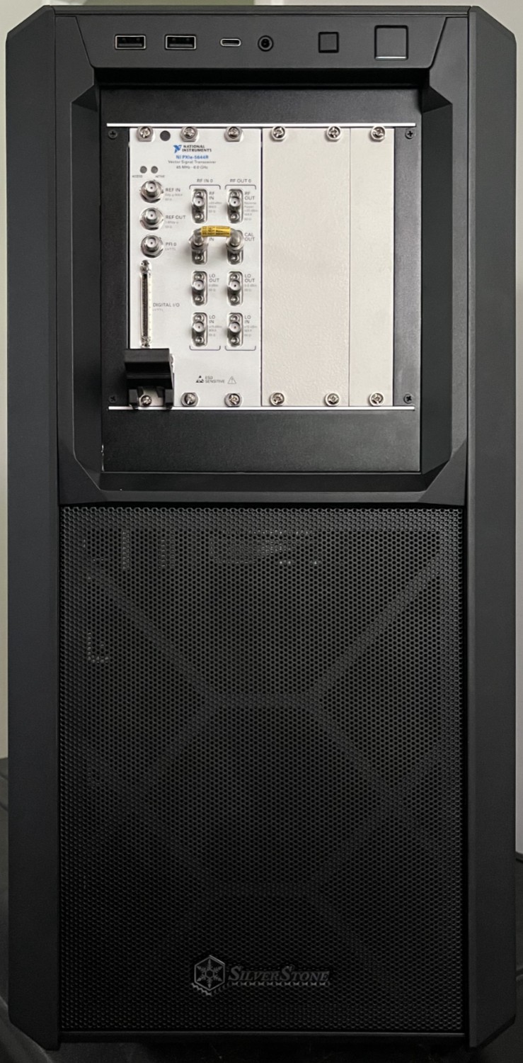
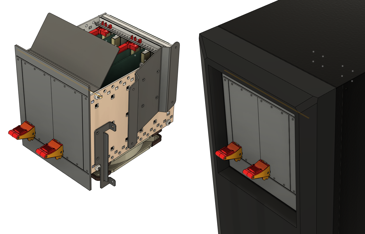
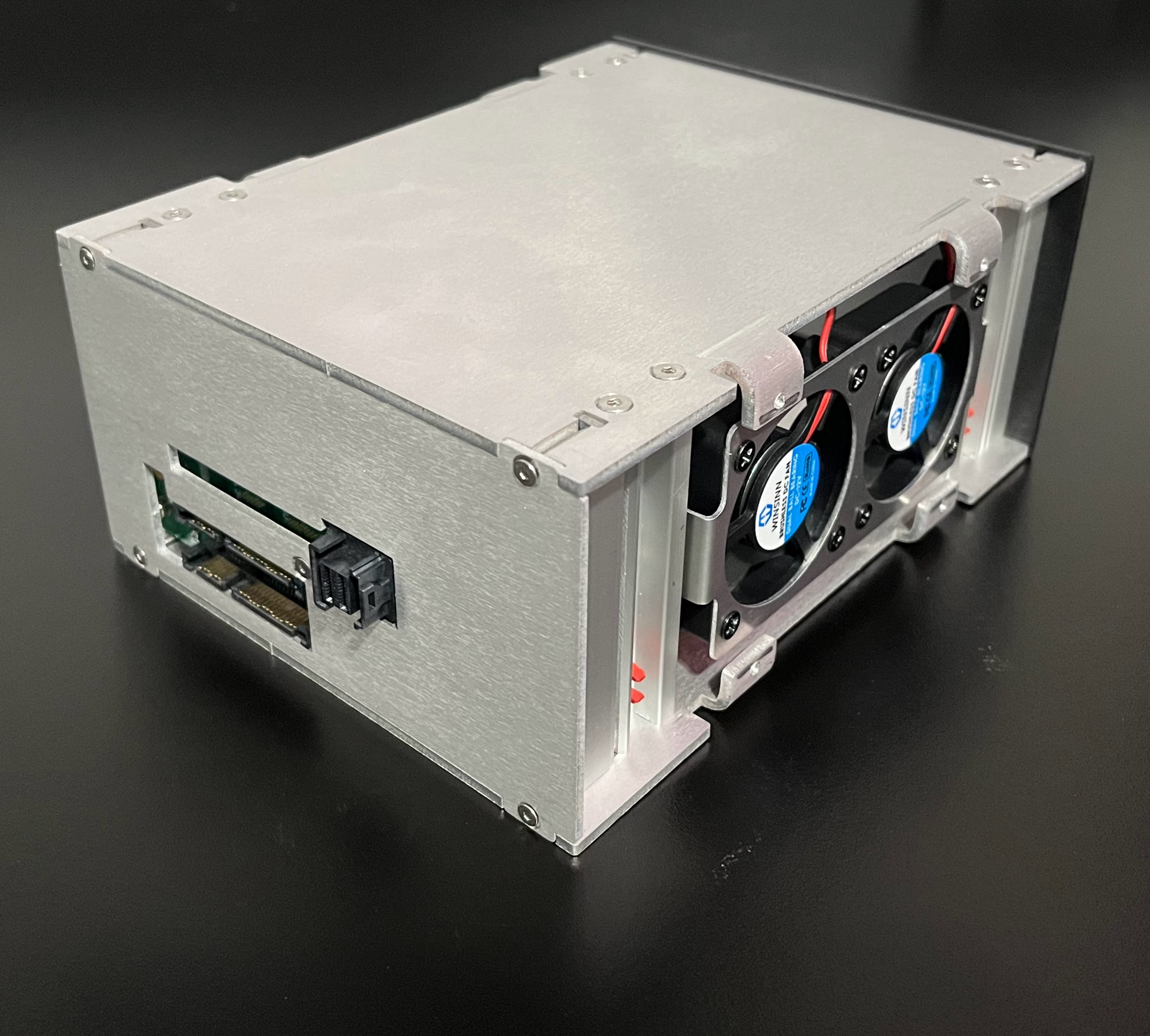
Rev B. hardware done. Assembled in a SilverStone SETA D1 case. It supports 2 instruments side-by-side, but that is yet to be tested.
Goals?
Finish Rev B. hardware - DONE!
Publish the journey and the results here
Make GNU Radio source and sink modules for the VST
Maybe write a swept SA + tracking generator app
Files
pressfit backing 2.3mf
3D printed piece to aid with press-fit connector installation
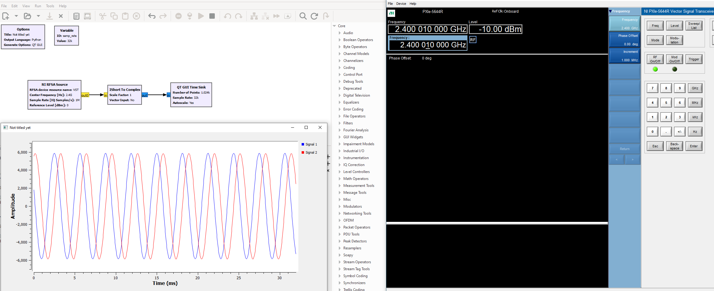
After quite a bit of struggle I managed to get a GNU Radio source block going for the VST analyzer part. It's very basic at the moment, but it builds and runs.
I never really had a plan about how far to take this, so for the moment I just enjoy hating everything related, like conda, c++, pybind and a million other things that I have no (usable) knowledge about. I'm learning a lot and that's good.
Next I'll build another mini-backplane pcb to try 2 instruments side-by-side. Unfortunately the refurb dell motherboard I'm using doesn't support PCIe bifurcation so I'll need two separate miniSAS adapter cards, but I still have empty slots.
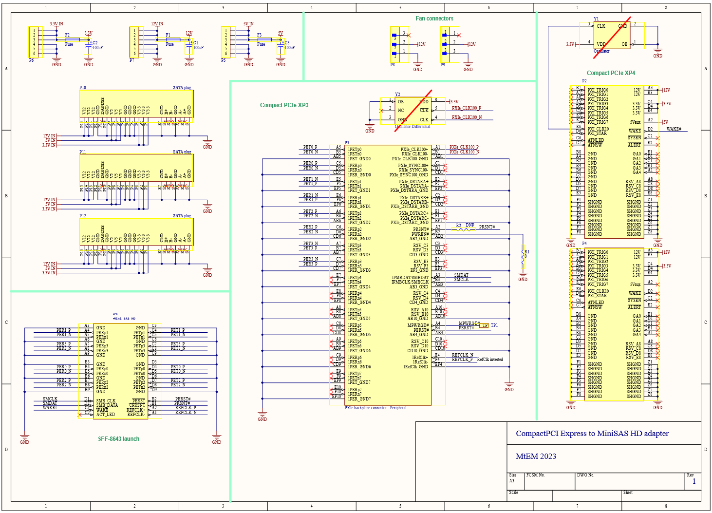
One of the nice things about this whole concept is that -by coincidence- there is no need to mess with a power supply / regulator circuitry for the PXIe instrument.
In general a module needs a +12V and a +3.3V rail and a +5V with negligible current draw. In case of the PXIe-5644R the spec sheet says the following:
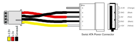
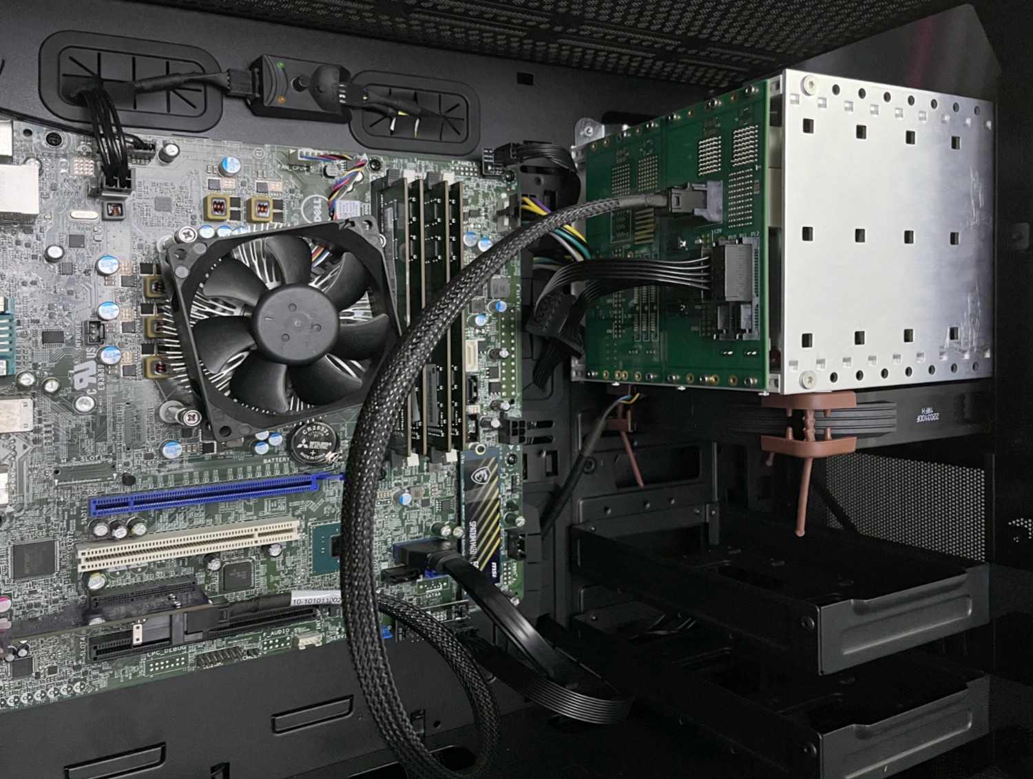
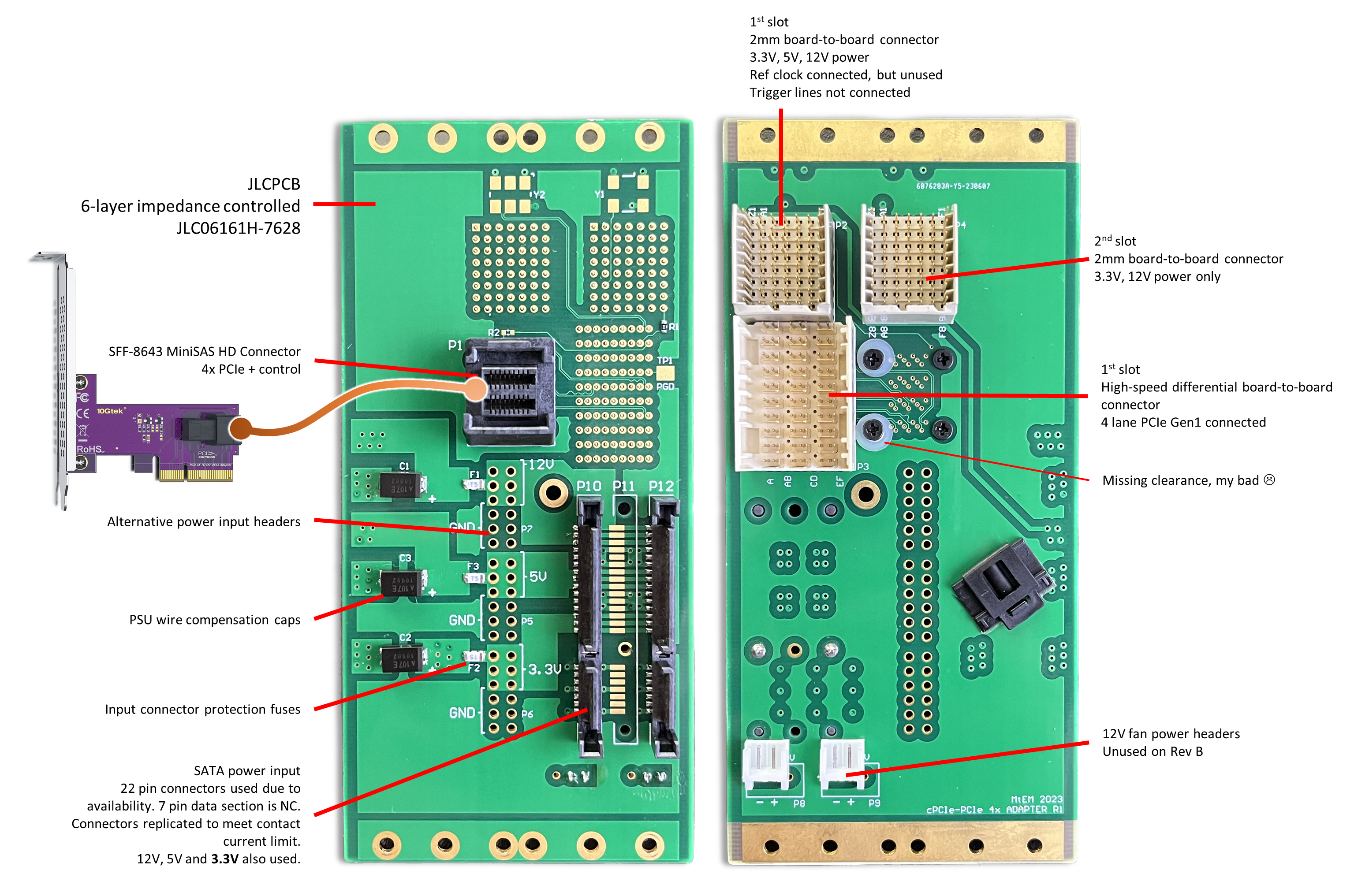
Luckily the SATA power lines from the ATX power supply contain all three. I couldn't find what's the story behind most storage drives only using +5V and +12V to the extent that adapters from the old 5pin power connector are very common. I wonder if I am just not aware of disks using 3.3V or it was for a future use case in the standard that never become reality. Anyway, the connector has the 3.3V rail and the PSU will supply it so the only thing is to check current ratings. This happened to be more difficult than I though, and I found contradicting information on the interwebz. The old(-ish) SATA standard I have defines the per contact minimum rating at 1.5A. On the 15 pin SATA power connector there are 3 contacts for each positive voltage, and 2x 3 shared for ground. Since the 5V current draw is either zero or very small we can ignore that, thus both 3.3V and 12V have 3 contacts each in both directions giving a combined limit of 4.5A per rail. I put 3x SATA power inputs on the PCB, but only populated 2, for a maximum of 9A input per power rail over the connector contacts. (As a side note it is fortunate that 2 connectors is enough, because I spaced them too close on the board, not taking into account the protruding part of the cable connector. Since 2 is sufficient, I just left the middle one unpopulated.) The PXIe module has its own power conditioning and voltage regulation stage, but I still felt like I had to do something to compensate for the fact that the power is not delivered directly from a low impedance trace on the backplane, but through ~2 feet of wire, from a commercial psu. As a wholeheartedly half-a$$ed solution I put a 100uF tantalum polymer cap on each input voltage rail. I read something somewhere... I'm using 16 AWG wire, which is plenty thick and the MSI MPG A650GF psu can supply enough power for 2 PXIe-5644Rs.
Since I didn't want to connect any disks to the same SATA power lines, I decided to make new point to point cables for them
I'm very happy with how the mechanical integration came together. There are a couple of screw holes that don't line up with the PC case, but the cage is still held firm.
Tell me it doesn't look like it came out of a factory.
The difficult part was to figure out the signal assignment through the MiniSAS link.
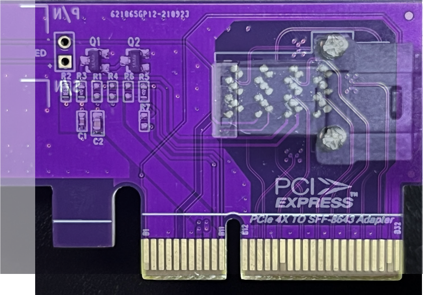
MiniSAS HD is an SNIA spec, namely SFF-8643. Standard documents have tables detailing how PCIe can be routed over the cables and connectors of the interface. I bought a PCIe-MiniSAS HD adapter board on Amazon but that didn't follow the pinout in the SINA documents. These kind of adapter boards are used for storage devices, so I'm sure there's a reason why their signals assignment is that way, but I couldn't make sense of it so I had to reverse engineer based on the hardware.
Yet another difficulty was that on the adapter board the PCIe Reset signal was seemingly not connected. Maybe it's not needed for the storage devices or I just got two faulty units? I ended up populating one of the empty resistors with 470R. I overlapped photos from both sides of the card to trace back which PCIe line goes to which MiniSAS pin.
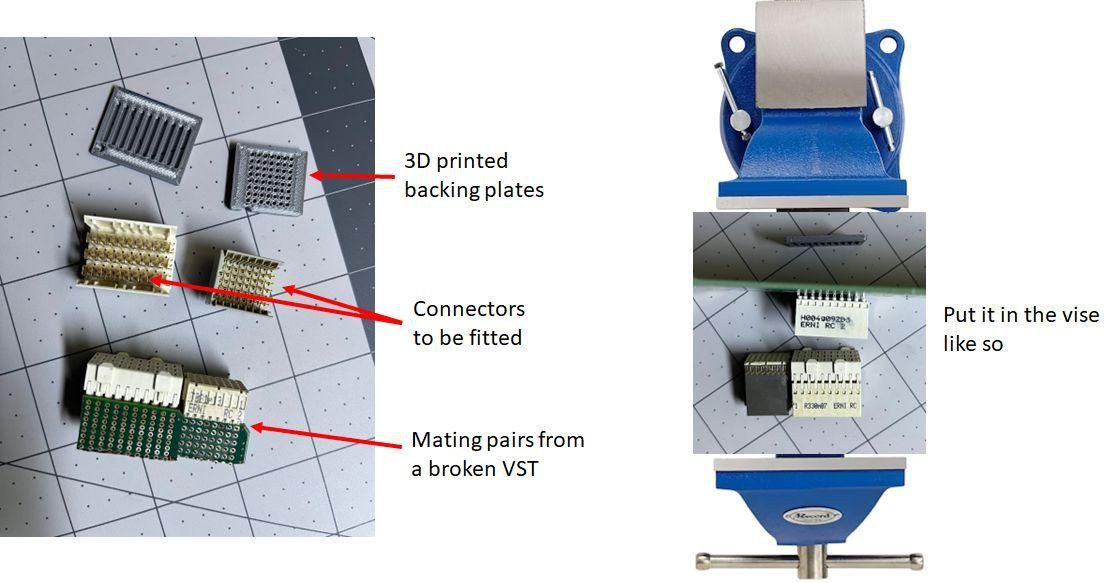
Very Interesting work, are these connectors (2684-973062-ND, A144744-ND) are pushed in to the PCB using a special tool? Also which resistor did you populated with 470R (among R1,R4,R6,R7) on the adapter board?
All 3 interface connectors, including A123726-ND are press-fit. I don't have a tool, but used their respective mating pairs from a broken board and a small 3D printed backing piece then pressed it together in a vise. I'll upload a pic. I think I added the 470R to R4, but I would have to double check. Other similar MiniSAS boards seem to have the resistor in place.
Appreciate your replay. you mind sharing a model the 3 d printed backing piece that I can print too? because I am figuring out now that cant push the connectors all the way in with out these backing piece.
That's not in GNURadio I just put the window next to it. It's the signal generator application that ships with the driver. It can do CW generation, simple modulated waveforms and arb playback. I wanted to write a GNURadio block for the generator part too, but I got stuck going down the rabbit hole of custom buffers and found other stuff to do.
May I ask if you could upload a PCB? I would like to manufacture a PXIe-4065 oscilloscope board that runs Ni. The price of this oscilloscope card is also very low, but I don't have a suitable PXIE slot to drive it
Hi @SophonGo, I was planning on doing that, but I want to do some cleanup work on it before and I am not there yet. On a related note the PXI-4065 has a PXI interface, not PXIe and would not work at all with my adapter board. You could use something like this: https://www.ebay.com/itm/114575958813
Sorry, I made a mistake in describing it. It's actually a PXIE-5160 board. I am patiently waiting for you to clean up your work. Thank you. I have also used the PCI to cPCI adapter card, which works stably, but can only be used for temporary debugging.
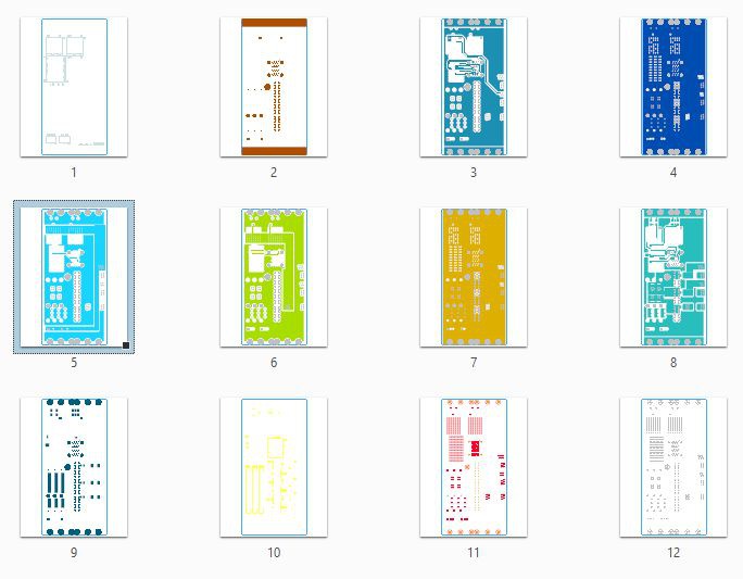
@SophonGo The gerber files, PCB BOM and fab instructions are up. See the relevant project update and the attached zip file. If you build it let me know how it goes. Have fun!
Thank you for sharing. The PCB has been produced and we are currently purchasing the required connectors and components. I will report back to you when there is progress in the test.
Also, gnuradio support is on my short list. In fact, I landed on this page by Googling "PXIe-5644R gnuradio" to see if anyone was working on it. I've never touched gnuradio, but do have Python experience and have been wanting to. Happy to collaborate.
That might be cool. I installed radioconda on the pxi desktop to start figuring out how to build a OOT module. I suspect that has to be in C++ first to seamlessly interface with the NI RFSA API. NI did python mappers for lot of modular instrument apis, but RFSA/RFSG is not in there. It shouldn't be that very complicated. I'm envisioning a simple sink block first with limited settings.
I also wanted to do this publicly, get it on github, which I haven't done before. Maybe you can give some guidance on that part,
Nice work!! I'm watching this with rapt attention! I too noticed the precipitous drop in prices for the 5644R and picked one up. Unfortunately, while I have a PXIe backplane, I don't have a PC interface for it. I do have a PXIe-8106 controller up and running Windows 7, but would prefer to bridge the backplane to something from this decade. Any advice for something other than the stock NI solutions (PXIe-8360 and the like)?
As you point out, your work seems like a great resource for interfacing any PXIe peripheral into a desktop environment, which could open up a world of possibilities for aspiring hobbyists who don't want to delve deep into the NI ecosystem.
Thank you! I have a full PXI set too, but my 8133 isn't a speed champion either. And the chassis is loud. Regardless one thing you could try is the PXIe-8379, which is a Thunderbolt 2 remote controller. You can pick one up between $3-400 on eBay. An apple Thunderbolt 2 to 3 adapter is ~$50, then you only need a computer / laptop that decides to work with it. I bought an Intel NUC for this purpose but couldn't make it run due to some legacy thunderbolt security setting in the bios. My old Lenovo work laptop was super happy with that setup.
Also if you don't mind spending a few hundred bucks you can build what I have. I was planning to upload the part list and I can just send you a bare PCB. I have a bunch of spares.
Well, that escalated quickly. I scored an 8379 on eBay for $250 just now, so we'll go with that. Thanks for the pointer! I have a bunch of other modules in that mainframe so it makes sense for me to go the mainframe route. Guess there's industrial hearing protection in my future. I still may be interested in working with your hardware just out of principal, to advance the state of PXIe hacking.
@Ward Apparently I can't reply to your latest comment. Strange. Anyway I'm glad you found a solution. I hope it will work with whatever you plan to plug it into. I tried once a Thunderbolt 2 PCIe expansion card, but those work in some mysterious ways too with supported motherboards / chipsets only. The PXIe-8301 is the newer version of the same concept and I'm guessing it has improved compatibility, but I've never seen it cheaper than its new price, which is ~$1700 at Newark right now.
I think it *should* be straightforward. Intel NUC13 Extreme with Thunderbolt 4 natively available. I got the Apple TB3-TB2 adapter and a cable, so we'll see how that goes. I've been watching the 8301 for some time, but yeah, pricey. Rather save that cash for test gear.
This project looks super interesting. I think that requiring a custom case would not be an issue at all for most hobbyists. Having it in a custom form factor would be more convenient for my form factor anyways. I am excited to see what progress you will make.
Thank you! I was torn about it. I was so glad first when I realized the VST would fit into a double 5.25 bay. I think that form factor was great. The case mod got really ugly though.
Here are some pics. I don't even want to upload here 'cause I don't want it in the project gallery. :D https://ibb.co/wp5hw8v https://ibb.co/8bNQ9sN
I have very generous metalworking capabilities but this was still a lot of effort and struggle and I'm not happy with how it looks, feels and how reproducible it is.
The new, bigger card cage could still be put into another chassis if there's enough willingness and competence with the dremel.
What would you integrate this into? I was also considering making it external. MiniSAS HD has a good external version, but I stopped because the power would be difficult. Either it needs to run from AC and have a 3 rail PSU in the enclosure, or I would have to find a way to break out power from the PC case and route it alongside the PCIe.
 Marsupilami
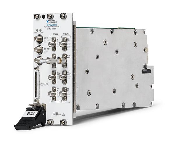
 Anyway, the connector has the 3.3V rail and the PSU will supply it so the only thing is to check current ratings. This happened to be more difficult than I though, and I found contradicting information on the interwebz. The old(-ish) SATA standard I have defines the per contact minimum rating at 1.5A. On the 15 pin SATA power connector there are 3 contacts for each positive voltage, and 2x 3 shared for ground. Since the 5V current draw is either zero or very small we can ignore that, thus both 3.3V and 12V have 3 contacts each in both directions giving a combined limit of 4.5A per rail.
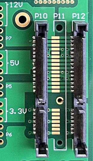 I'm using 16 AWG wire, which is plenty thick and the MSI MPG A650GF psu can supply enough power for 2 PXIe-5644Rs.

 The difficult part was to figure out the signal assignment through the MiniSAS link.
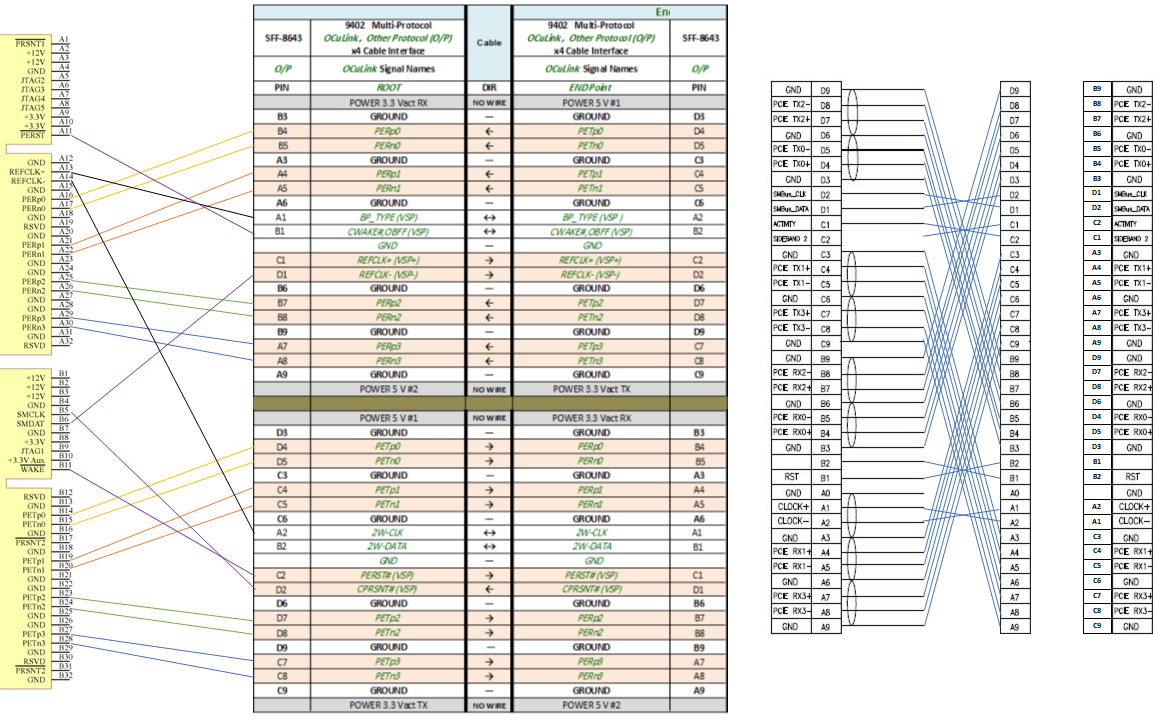 Yet another difficulty was that on the adapter board the PCIe Reset signal was seemingly not connected. Maybe it's not needed for the storage devices or I just got two faulty units? I ended up populating one of the empty resistors with 470R.
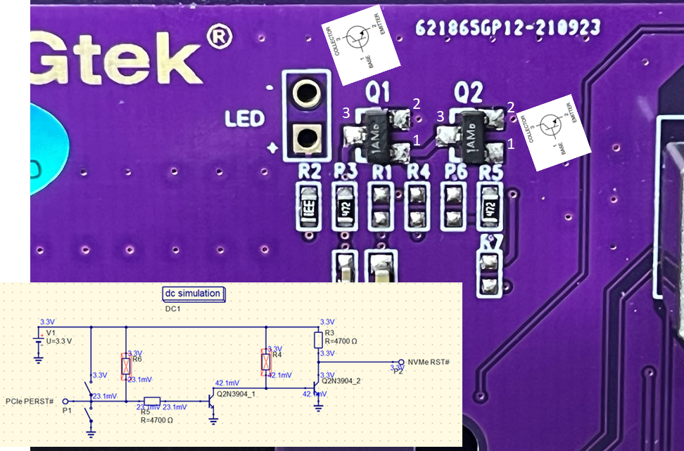


 SukkoPera

 c.Invent
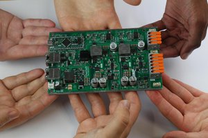
 Jean Alinei
Very Interesting work, are these connectors (2684-973062-ND, A144744-ND) are pushed in to the PCB using a special tool? Also which resistor did you populated with 470R (among R1,R4,R6,R7) on the adapter board?