Close
0%
0%

FunKey project - All your games on your keychain !

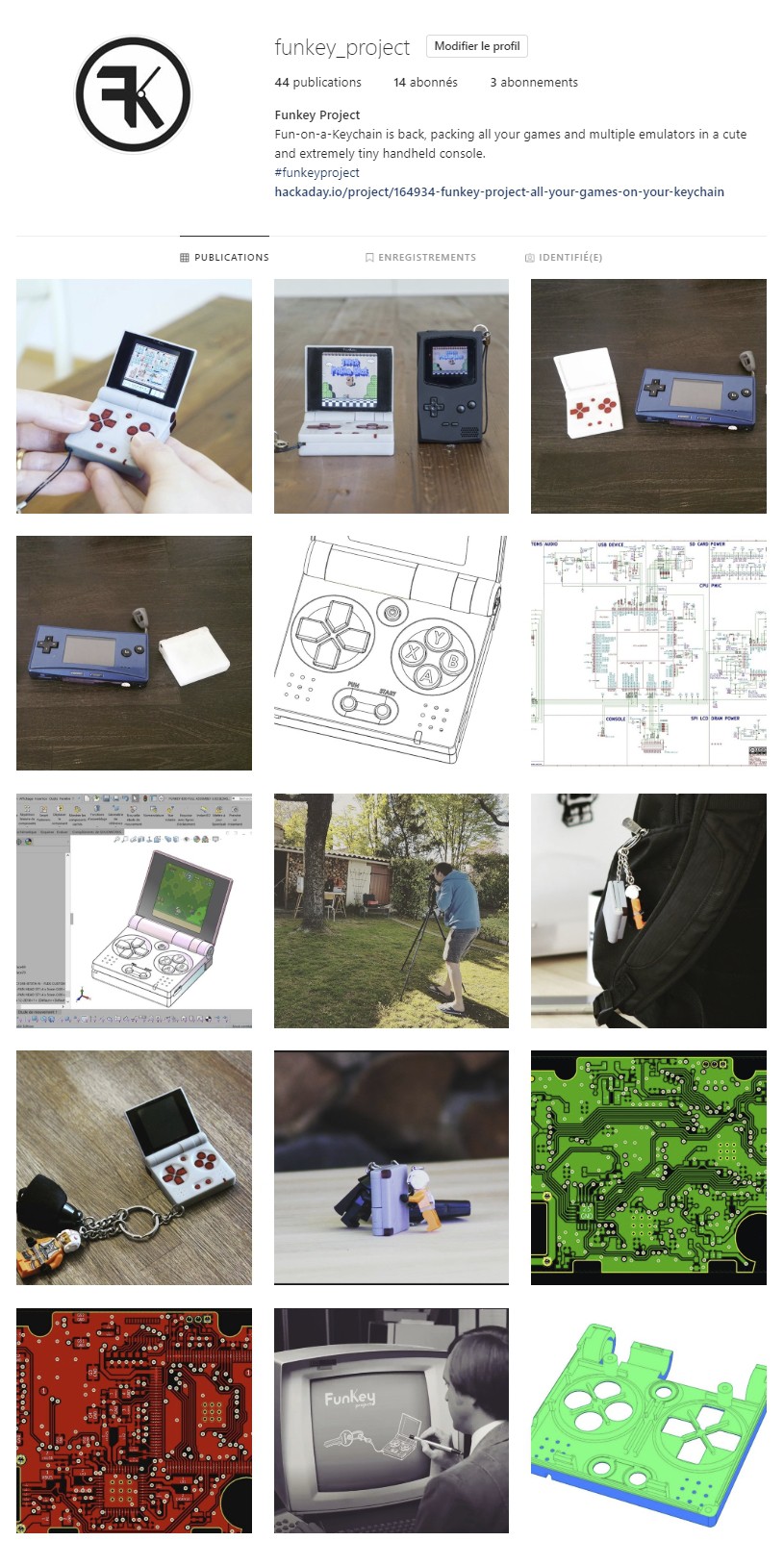
Fun-on-a-Keychain is back, packing all your games and multiple emulators in a cute and extremely tiny handheld console.

Public Chat
Similar projects worth following
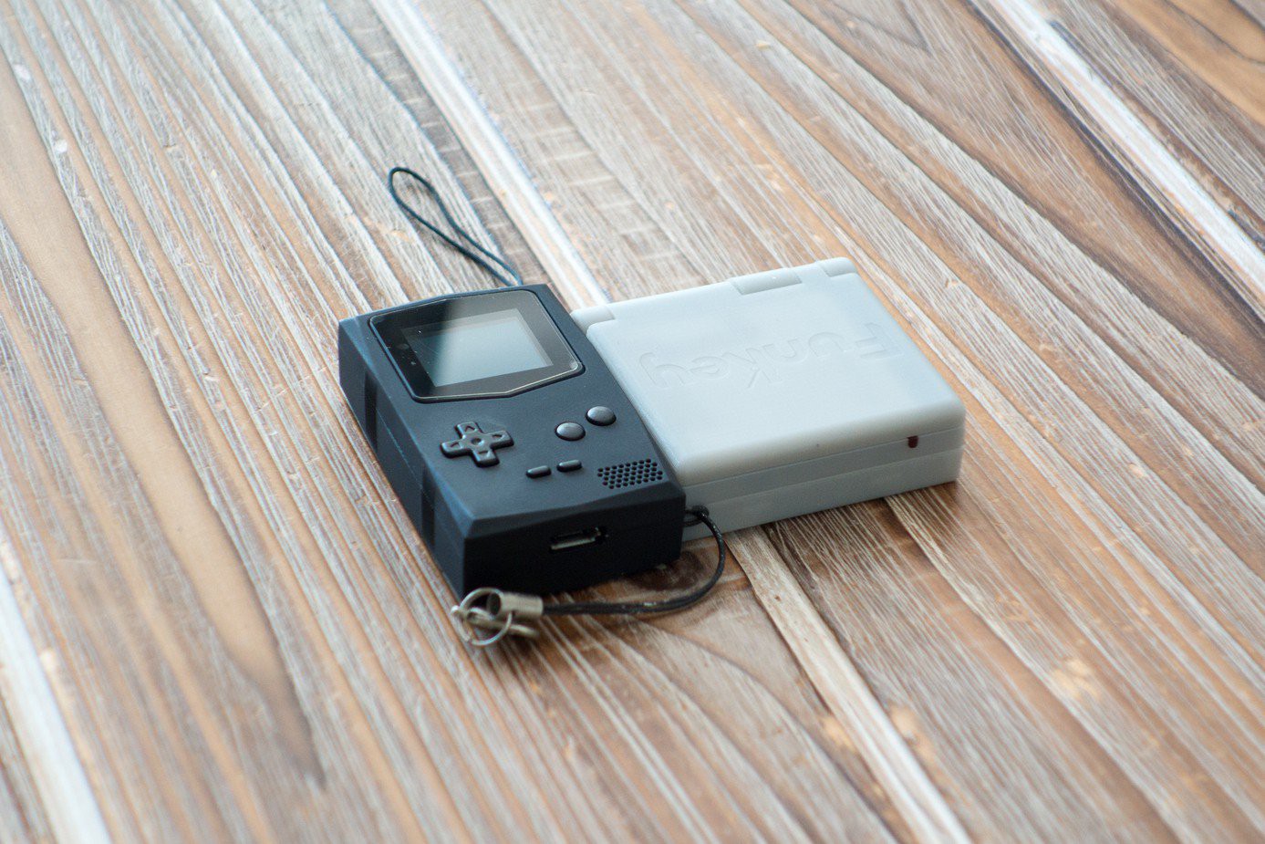
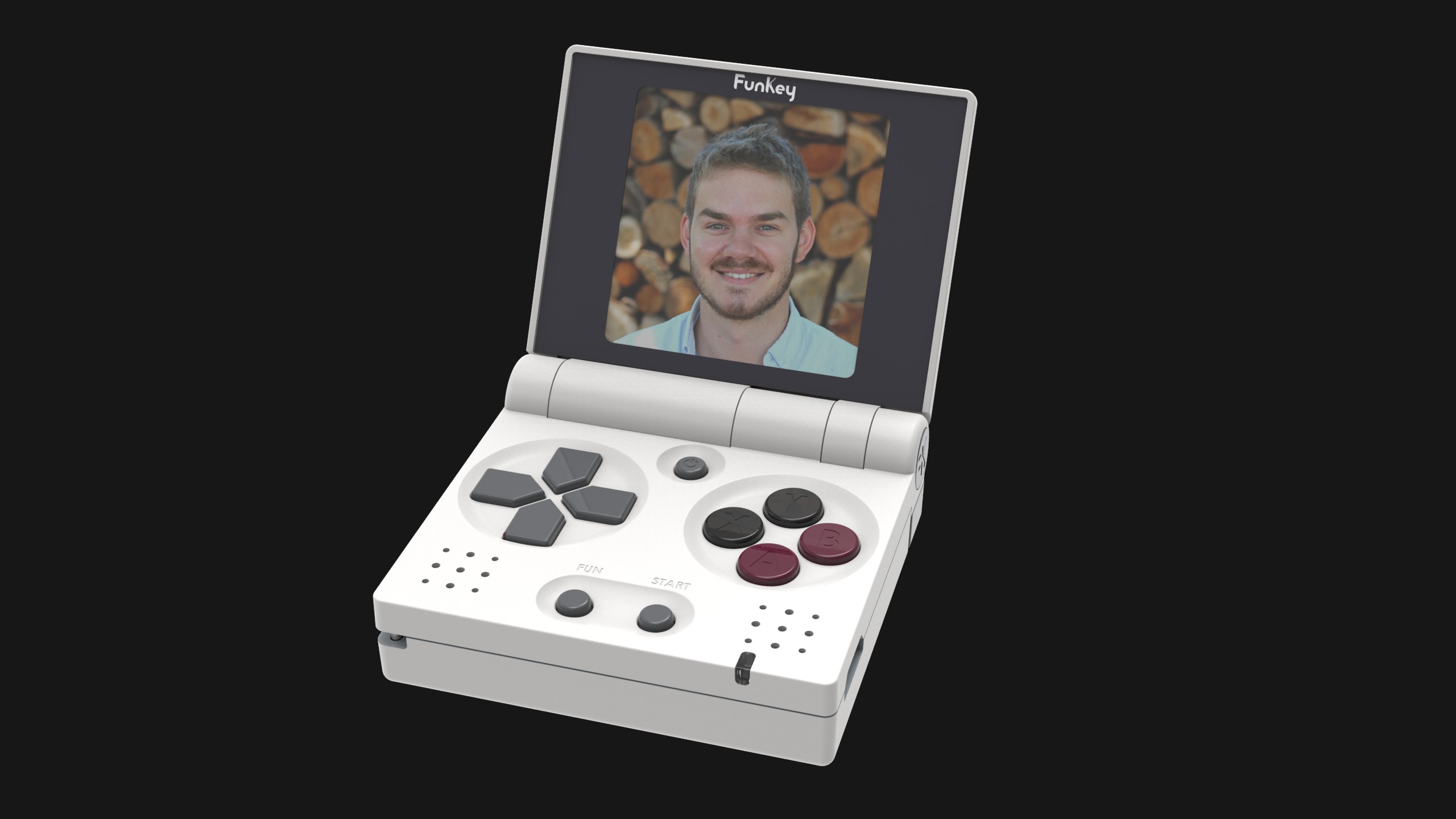
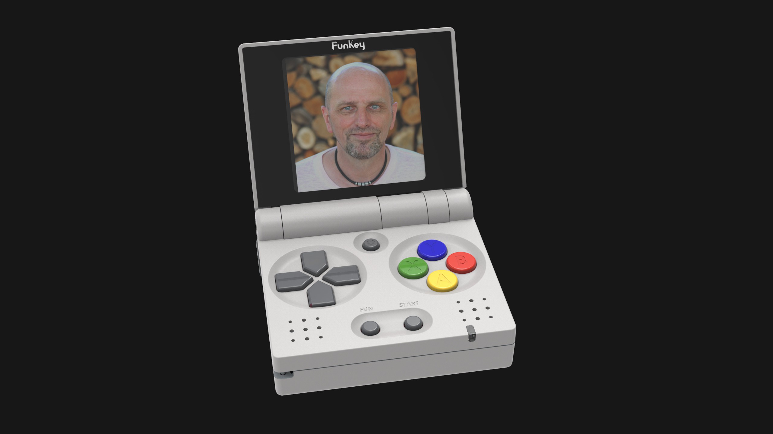
FunKey is a tiny yet comfortably playable multi-emulator handheld gaming console that anyone can carry on their keychain. Bored in transports, sleeping in class or simply having a few minutes to kill? Pop up your FunKey from your ever-carried keychain and start back your favorite game right where you left it.

Its foldable design allows for large comfortable buttons, optimized screen space, and a strong protected shell when closed, while its Allwinner 1Ghz A7 processor coupled with a full Linux distribution built from scratch are powerful enough to allow you to play your favorite retro consoles at full speed (NES, SNES, Gameboy, GBA, PS1, Sega Genesis, Sega Master System) while being optimized for battery life.

As always with our previous experiences (Keymu, Funkey Zero) the goal of FunKey is also to share the knowledge, that is why our ideas, designs, programs and experiences will all be layed out on this very page.

We hope you’ll come to love FunKey as much as we do.


Project Logs

General

Alive and Kicking
Photo shoot side by side with PocketSprite
FunKey gets social ! (Website, newsletter and social networks)
FunKey Revision B is out!
 Meet the team
Project roadmap

Mechanical design

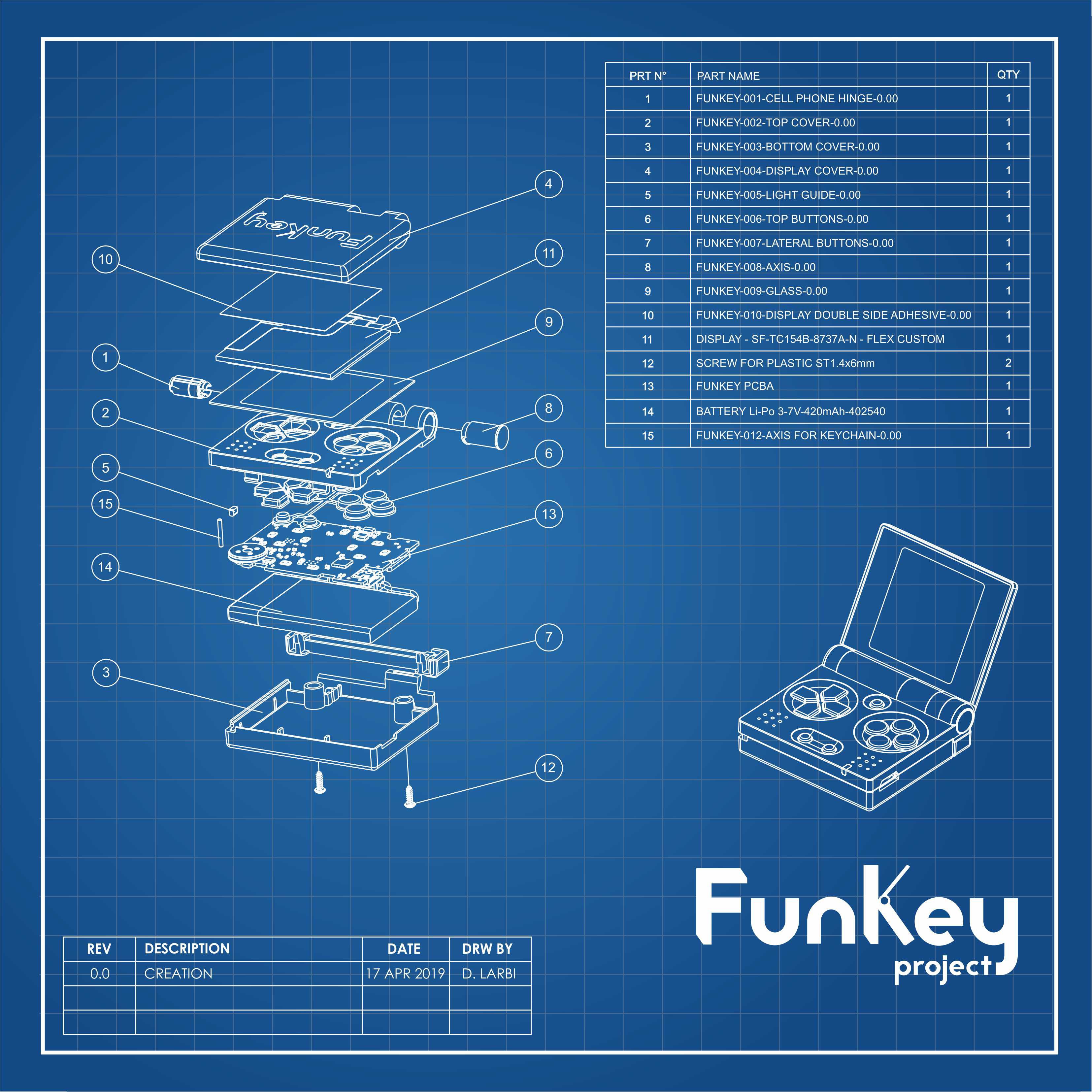
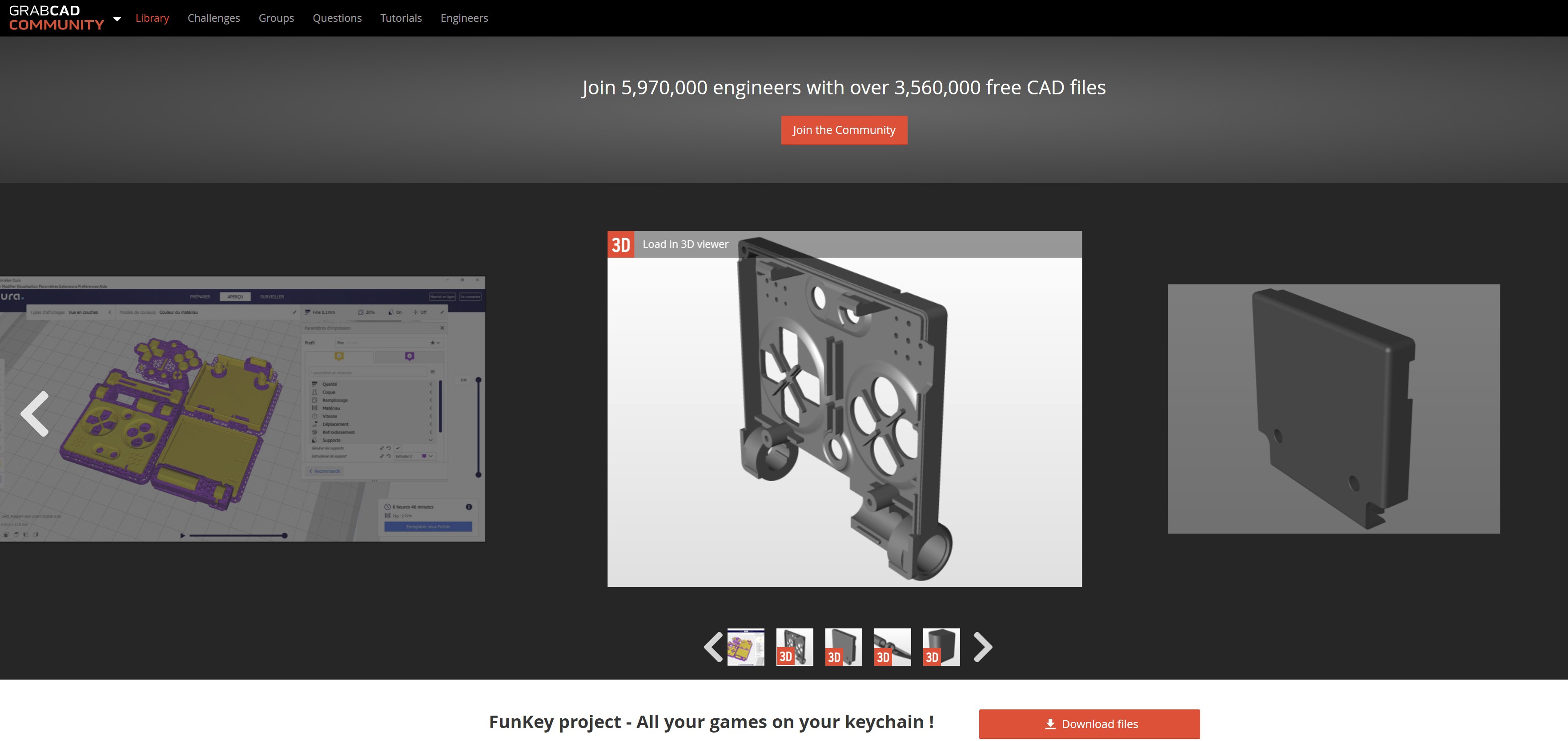
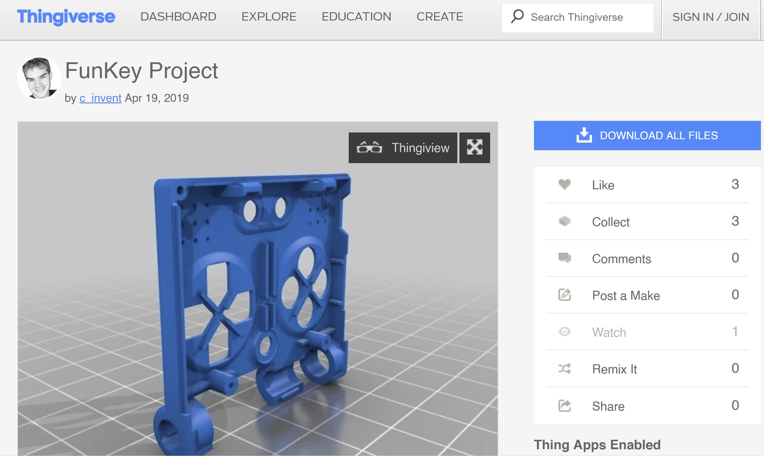
STL files and Exploded view
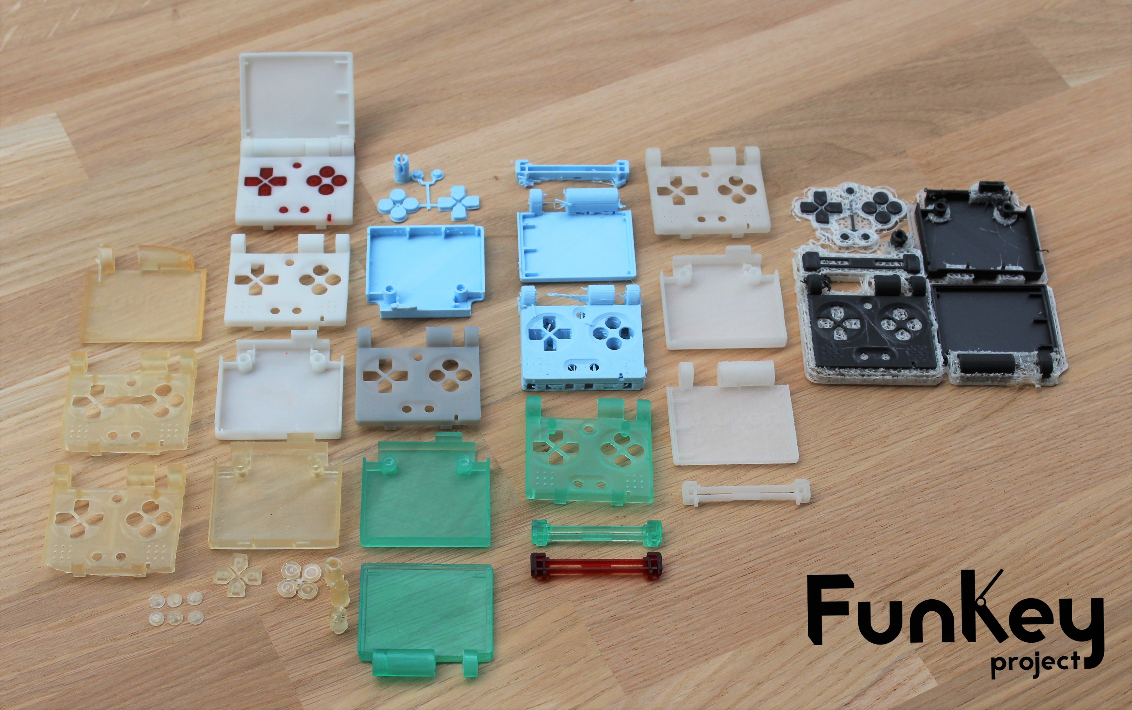
3D Printed prototypes before injection molding


Electronic Design

Electronic Parts
Electronic Design
Schematics: CPU
Regulated DC Power Supply Topologies
Why so many different Power Supply Voltages?
Schematics: PMIC
Schematics: DRAM Power
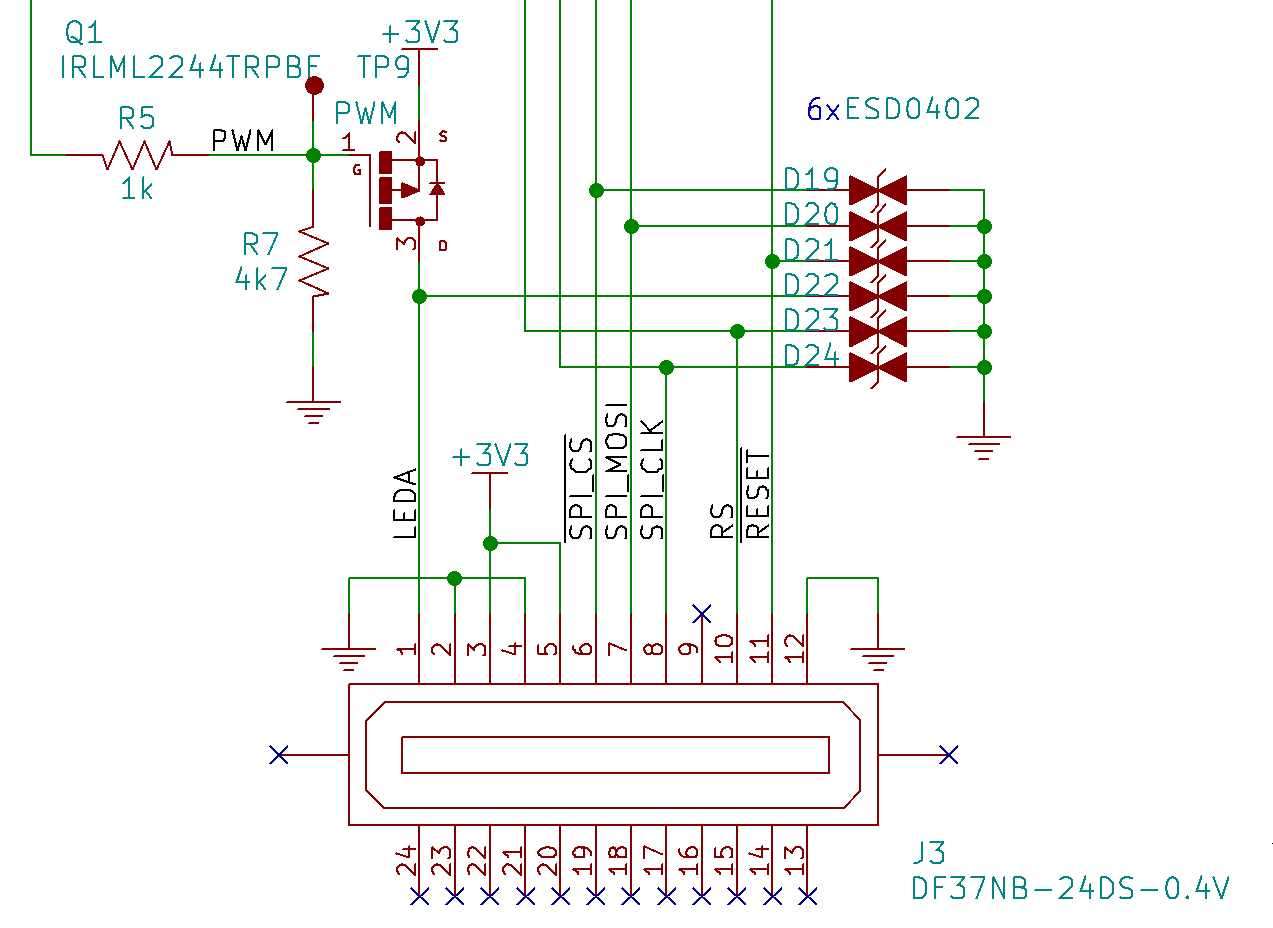
Schematics: SPI LCD
Schematics: Console
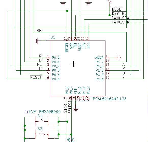
Schematics: Buttons
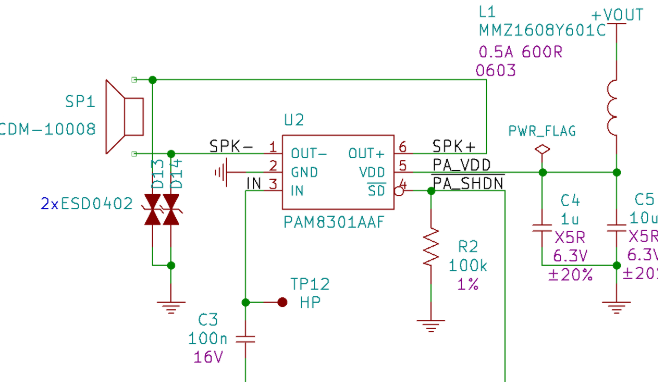
Schematics: Audio
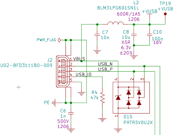
Schematics: USB
Schematics: SD Card
Schematics: Power
Layout: Screen FPC Extender
Layout: Screen FPC Extender Update


A bit of History

It’s now been a bit more than two years since we entered the HaD contest with Keymu: an open-source keychain-sized multi-emulator handheld console which received quite an unexpected success.

Keymu did not pretend to be more than a prototype destined to be built by anyone willing to get their hands dirty. And even though it was often asked to be produced and sold, the world of difference between prototyping and producing kind of humbled us into taking it slowly.

We first needed to focus on correcting electrical and software issues Keymu had, that is why we started working on a new prototype without a foldable design but with almost everything new under the hood. The prototype turned out pretty great, so much so that we decided to give it a name and enter once again the HaD prize: this was last year’s FunKey Zero.

A lot has happened in a year, among which the expansion of our team of enthusiasts to the grand number of three, now bringing together the much-needed professional mechanical hindsight to our electrical+software knowledge.

Keymu and its optimized design can now be born again, merging with all FunKey Zero’s improvements, thought for production and readier than ever to bring fun on your Keychain, meet the FunKey Project.

Characteristics

Dimensions

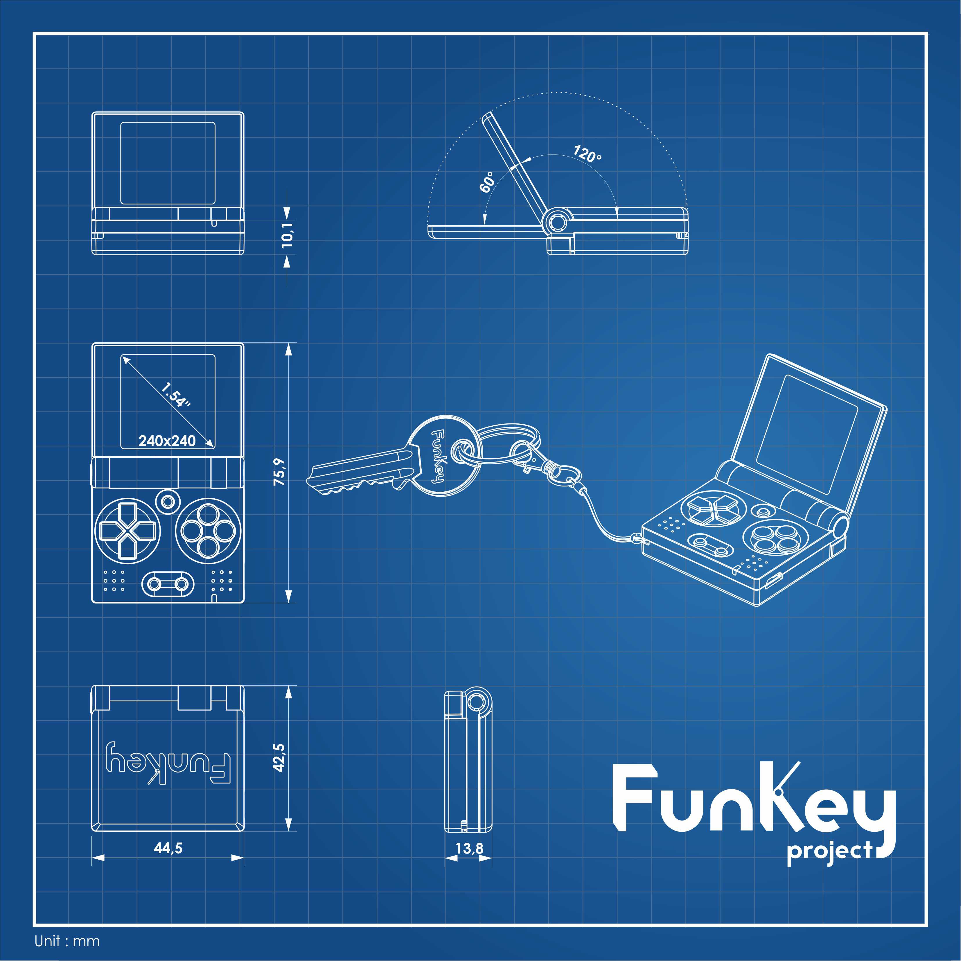
42.5x44.5x13.8 mm

Processor & RAM

ARM Cortex-A7 @ 1.2GHz. Extensions: NEON, VFPv4.

64MB of RAM DDR2 up to 400MHz

Storage

SD card 16GB

Display

LCD IPS screen, 1.52”, 240x240 px

Audio

10 mm mono speaker, 500mW

Battery

420mAh Li-ion battery for hours of gameplay

Recharging and loading games

via Micro USB port

What’s new?

Mechanical design

FunKey’s most discernable new features is the return of the foldable design but it's only the tip of the iceberg. Everything is new here, and of course the details will be presented more thoroughly in future logs but, to get a sense, here are the main new features:

  • The casing 

Completly rethought, it is now a slimmer package than Keymu and way smaller one than Funkey Zero: only 42.5x44.5x13.8 mm when closed. 

It is also now sturdier thanks to a combination of snap/fit parts and two small screws on the back.

  •  The active...
Read more »

FunKey Rev. B Schematics.pdf

For those who do not have KiCAD installed and/or just want to have a quick view at the schematics, here it is in PDF format.

Adobe Portable Document Format - 347.31 kB - 08/04/2019 at 17:50

Preview

FunKey Rev. B.zip

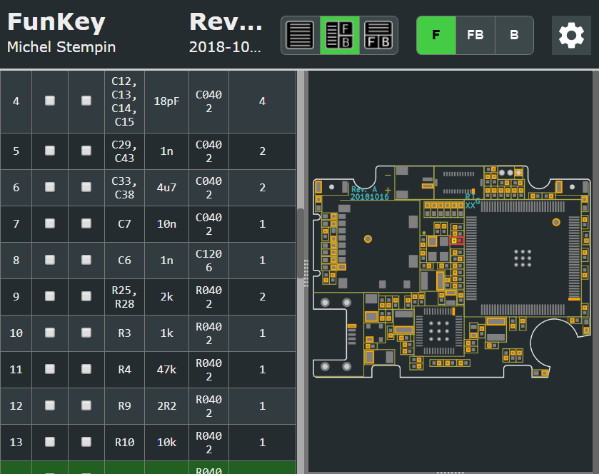
FunKey Rev. B schematics, layout and 3D parts

Zip Archive - 3.72 MB - 08/04/2019 at 17:48

Download

SW3dPS-JST_SM02B-SRSS-TB.STEP

Battery connector 1.0 mm pitch 3D STEP model

step - 237.13 kB - 05/15/2019 at 21:00

Download

eSH.pdf

Battery connector 1.0 mm pitch datasheet

Adobe Portable Document Format - 142.36 kB - 05/15/2019 at 21:00

Preview

vls252012cx-1.step

Power inductor 3D STEP model

step - 36.80 kB - 05/15/2019 at 20:41

Download

View all 39 files

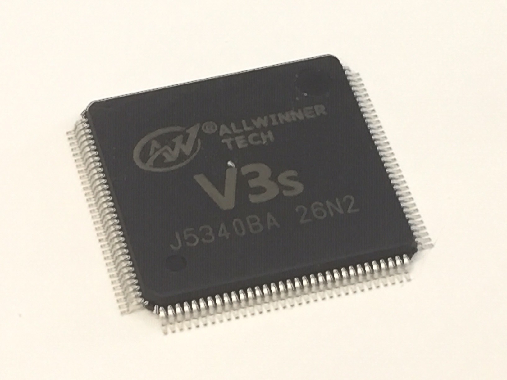
  • 1 × AllWinner V3s Cortex-A7 1.2GHz (ARM v7-A) Processor with integrated 64MB DRAM
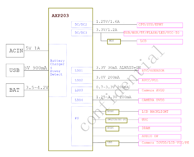
  • 1 × X-Powers AXP209 Power Management Unit
  • 1 × LED0402 Red LED 0402
  • 3 × Würth Electronics 74404032047 WE-LQS SMT Power Inductor
  • 1 × TDK VLS252012CX-M VLS-CX-1 SMT Power Inductor

View all 44 components

  • It's FunKey Day on Kickstarter!

    Squonk4207/01/2020 at 16:54 0 comments

    Here we are!

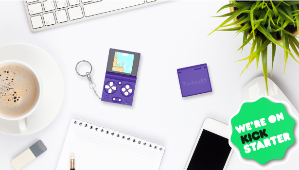
    This is the day we were all waiting for: we are offcially launching the FunKey S  - the world's smallest foldable handheld console - on Kickstarter today!

    You can check out the Kickstarter page here:https://www.kickstarter.com/projects/squonk/funkey-s-the-worlds-smallest-foldable-handheld-console

    We started over from #Keymu - open source keychain-sized gaming console , keeping only its foldable design and tiny aspect. The whole interface has been rethought, as well as the buttons, the screen, and many other aspects. The FunKey S is a real handheld console, powerful and comfortable, small enough to fit on any keychain, and able to let its owner play thousands of retro games.

    Over the last months we have been working very hard both on the hardware/software and on the communication level. Reviewed by some tech Youtubers, the FunKey S gained a great visibility, on social media as well. Kickstarter already added us to their “project we love” category and we expect the campaign to be a great success.

    And of course, we commit to make the design fully Open Hardware and Open Source 

    Since its origins FunKey has proudly been Open Hardware and Open Software!

    Many designs and tutorials are already online here on Hackaday and we commit to keep every aspect of the FunKey S open.

    This means putting in public repositories on Github:

    • all electronic design & production files
    • all drivers, system scripts & OS-level source files
    • all optimized launcher & emulator source files
    • all 3D-printable STL files for the casing

    Basically, you have the keys!

    Our basic Kickstarter price is $69 and the discounted price for early birds is $59.

    Don’t hesitate to write if you are interested and need any more info!

    You can also have a look at our social media:


  • Project Roadmap

    Squonk4208/20/2019 at 20:05 0 comments

    In this log, we want to share our experience of bringing our FunKey Project from its early-prototype stage to a "Ready For Manufacturing" / "Community-Ready" state necessary to launch a successful crowdfunding campaign that in turn should provide us with the lever required to launch a product in mass production. 

    Where Do We Come From

    People following the Funkey Project certainly remember that the original motivation came from @Sprite_tm's 2016 Hackaday superconference project of a pocket retro gaming console, that lead @c.Invent to develop the #Keymu - open source keychain-sized gaming console as a Proof-of-Concept that entered the 2017 Hackaday Prize. The corresponding Youtube video is now peaking at 4.8M views and #6 in Youtube's Popular Videos - Game Consoles & Mobile Phones category!

    Unfortunately, the tiny (and expensive) Intel Edison CPU module at the heart of the console was abruptly discontinued, which forced him to find a replacement module. Given the tiny dimensions, this prove to be very difficult, but @Squonk42 joined him to develop a new board around the LicheePi Zero module. Eventually, a new #Funkey Zero console which was used to validate the new CPU choice took part in the 2018 Hackaday Prize:

    At this point, it became clear that the main feature of the #Keymu - open source keychain-sized gaming console was its foldable design, providing a maximum size for both the screen and keypads in the smallest form factor. It also became clear that such a hinged design required the help of a professional mechanical designer, and this challenge motivated @David.Larbi who joined the team at the beginning of this year.

    Where Do We Stand

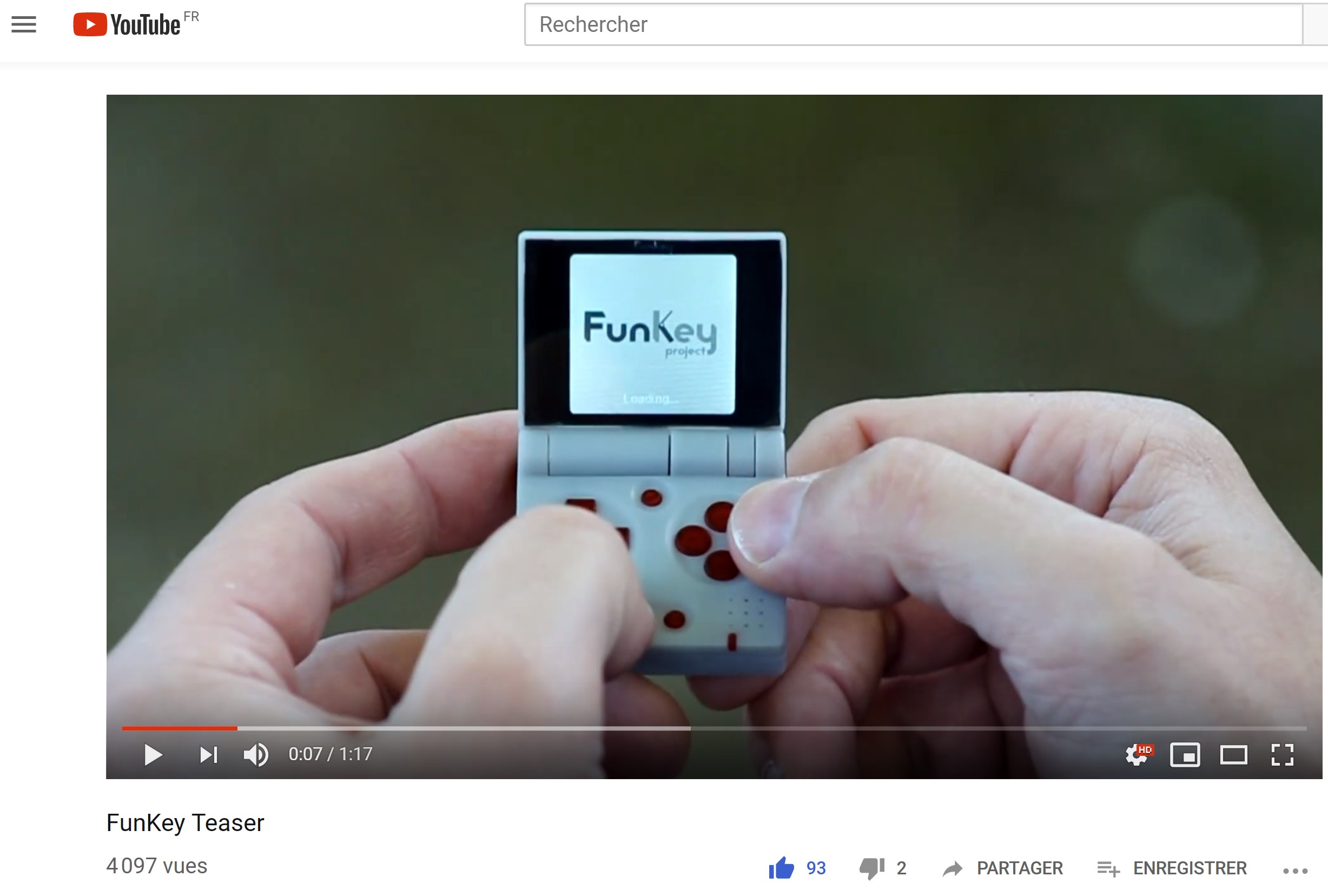
    With this team now formed, we achieved the development of two FunKey Revision A prototypes, which are demonstrated in the FunKey Project Teaser Video:

    But turning a prototype into a mass production device is not as easy at it seems... This is why we started the #FunKey project - All your games on your keychain ! and decided to take part in the 2019 Hackaday Prize, whose goal this year is precisely focused on product development!

    We seized this great opportunity to discuss with "Bunnie" Huang during a mentor session to help us find out where to go from here:

    Clearly, his advice was to find ASAP a manufacturing partner to scale up production!

    Where To Go From Here

    Crowdfunding

    From the start, it was clear for us that developing an electronic device like the FunKey Retro Gaming Console for mass production requires some cash money to buy the components, make the PCBs and assemble the parts (PCBA), but also to manufacture the enclosure injection molds and for the product fulfillment (certifications, packaging, storage, shipping, etc).

    As we all have a day-to-day job and were not willing to mortgage our house and car, we agreed that the only possible solution was to resort to crowdfunding instead of investing our own money.

    But it seems that today the time (if it ever existed!) of easy money through crowdfunding is over. Now, you need to have a sleek, professionally looking video, marketing arguments and both business and production plannings in order to end a campaign successfully.

    This quickly turns into a "chicken and egg" problem, as you need to evaluate the product cost that depends on how many units you will sell, which...

    Read more »

  • Layout: Screen FPC Extender Update

    Squonk4208/20/2019 at 17:53 0 comments

    The previous log detailed the screen FPC extender, used to adapt the stock LCD screen to the FunKey main PCB.

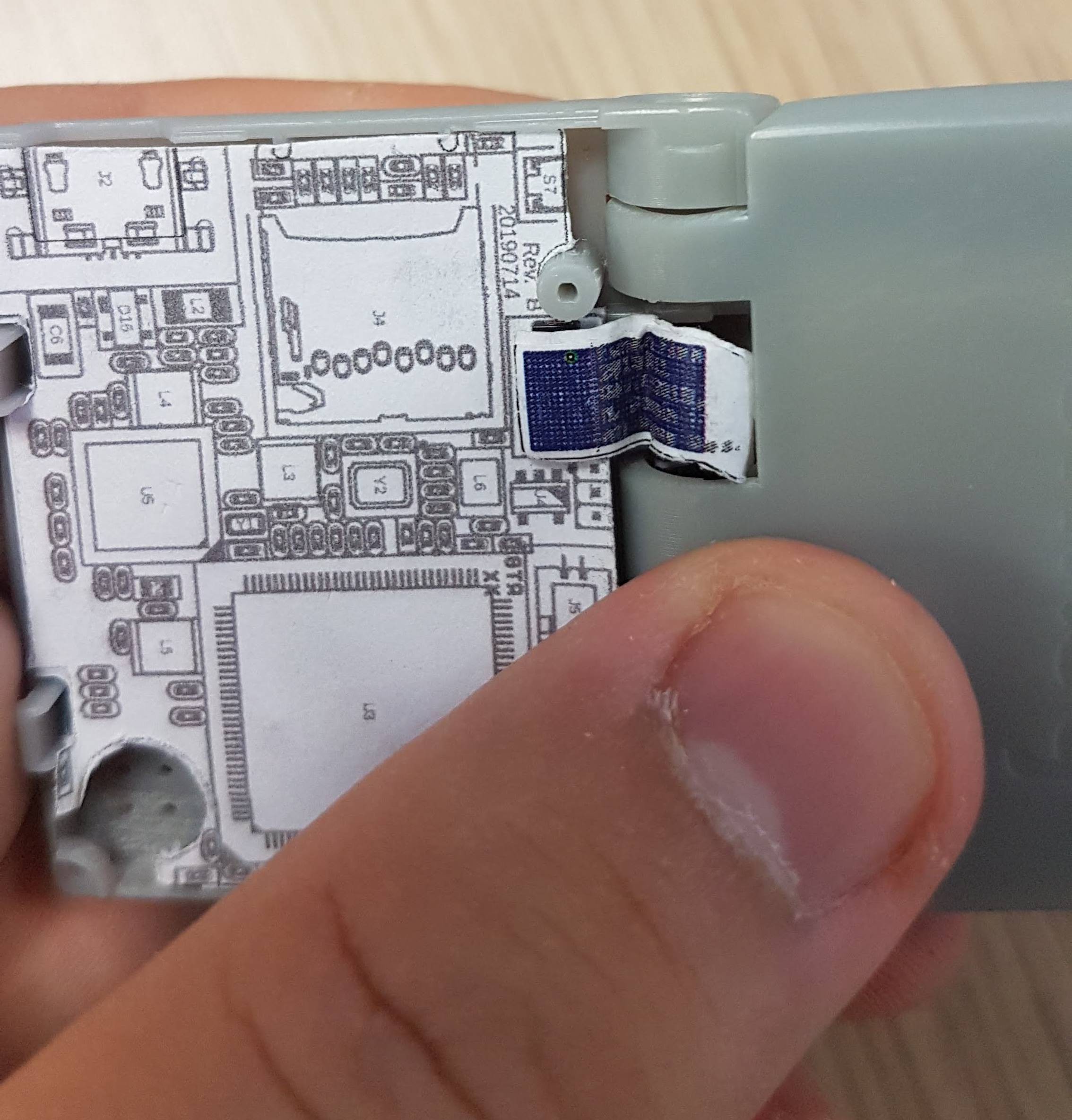
    Before launching the FPC fabrication which is quite expensive (~ $100 / 5 pieces), we decided to have a dry run using a paper mock-up. Here is the result:

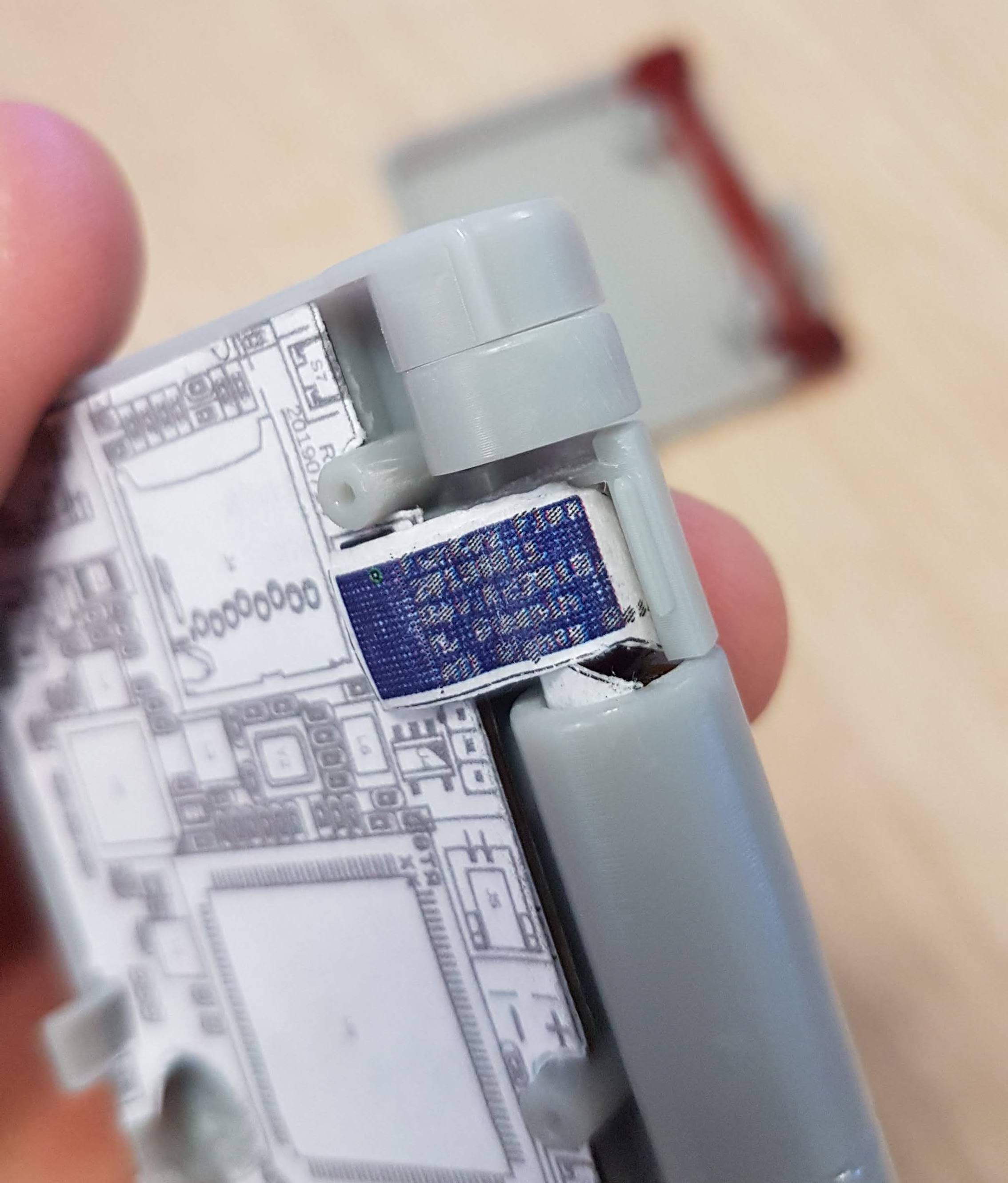
    We covered the old Rev. A PCB with a paper print of the new Rev. B one, and created a paper version of the flex, gluing the connectors on them at the right positions. As you can see, the result is not too bad.

    This was until we tried to open the lid flat:

    Well, the FPC is a little bit too long, causing a "wave" that totally defeats the original purpose of the "flypaper design": the small bend radius would certainly cause a failure sooner or later.

    Moreover, the FPC is a little bit too wide, too, so it interferes with the internal ribs somehow.

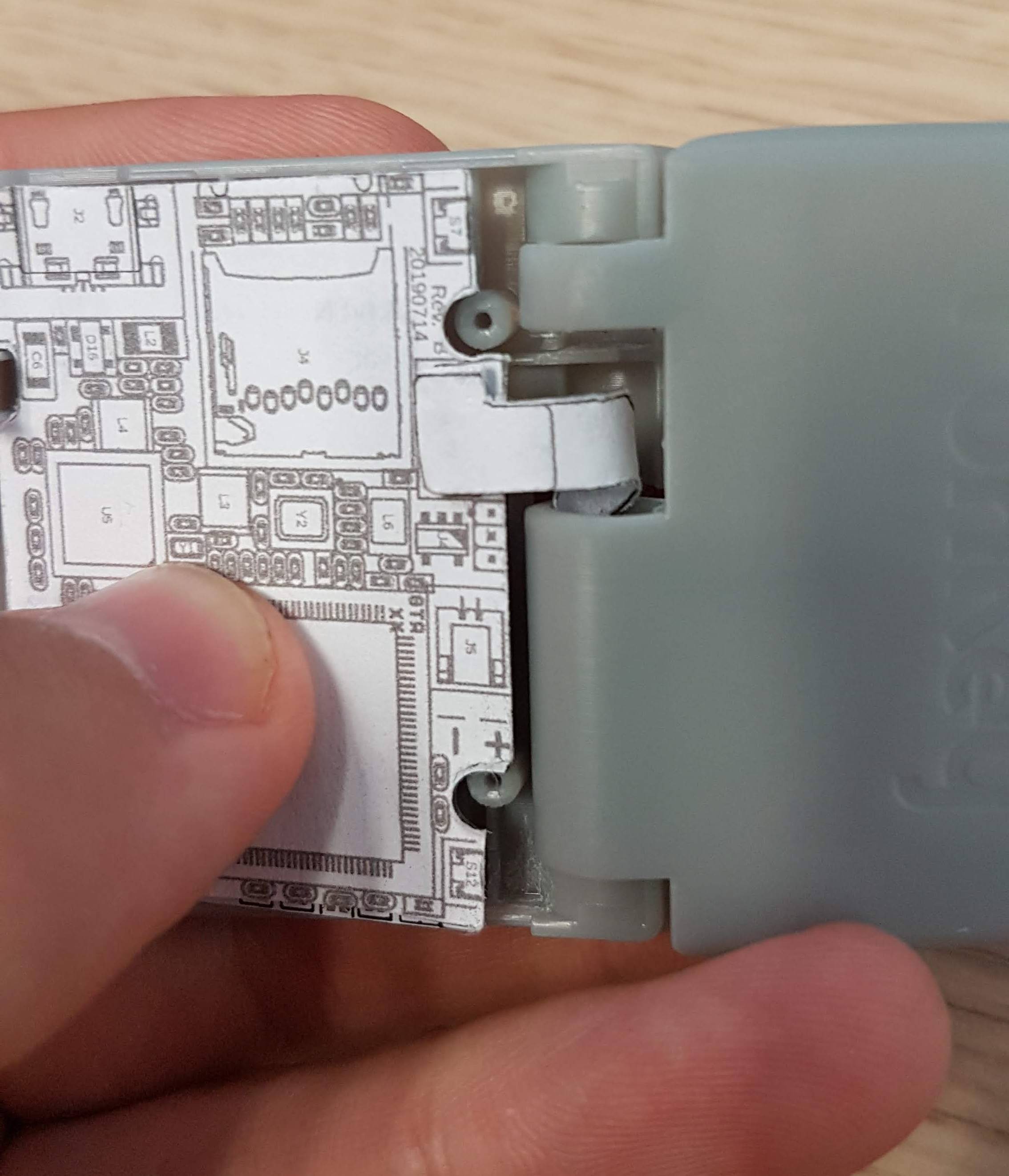
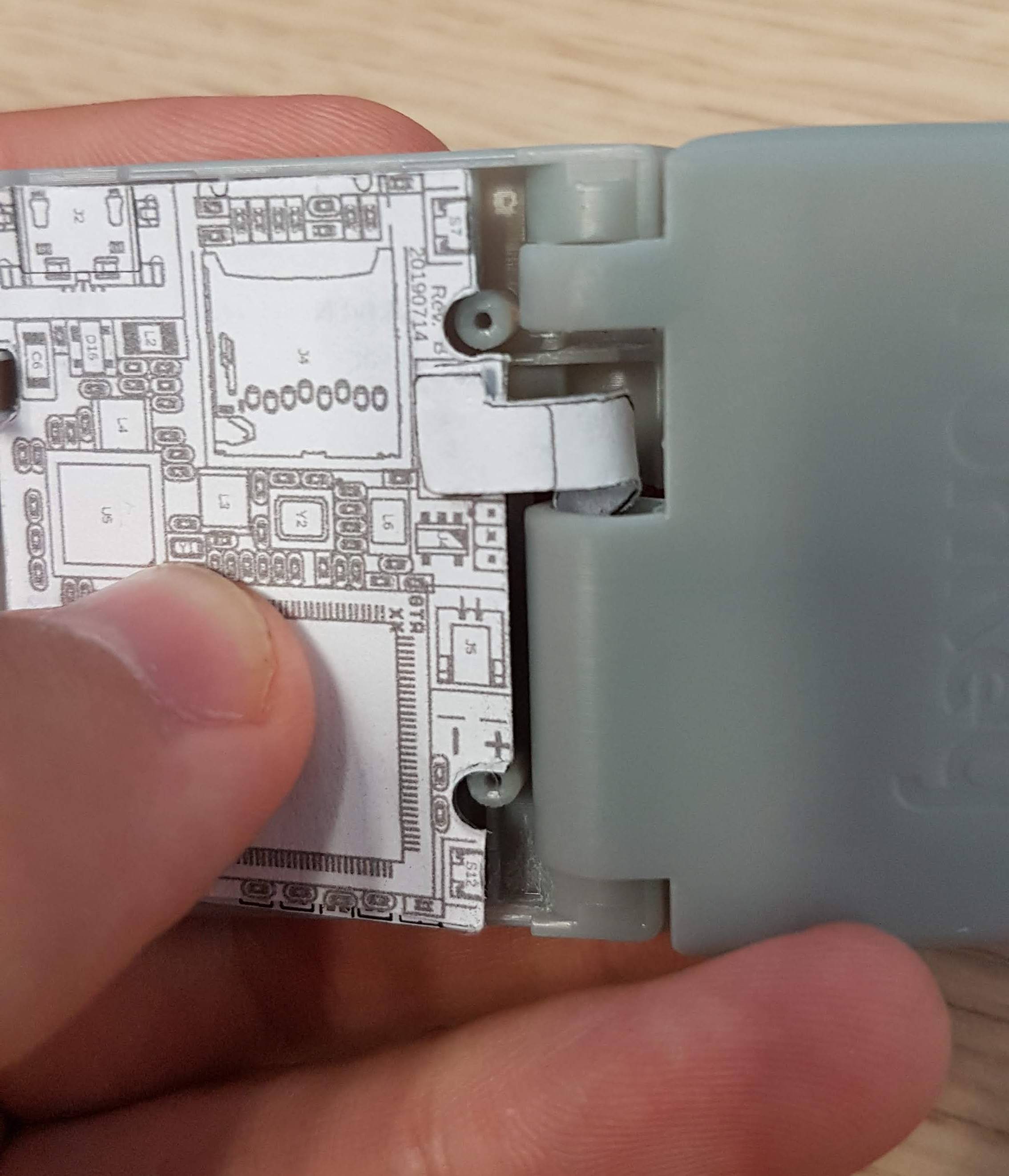
    So, back to the drawing board, we decreased the length by 2 mm, and the width to 4 mm, here is the result:

    Much better! And the behavior when opening / closing the lid is also improved:

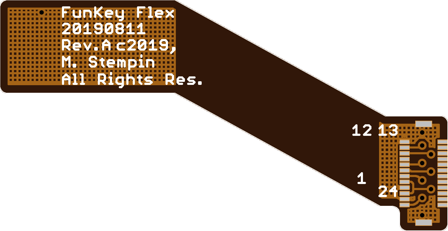
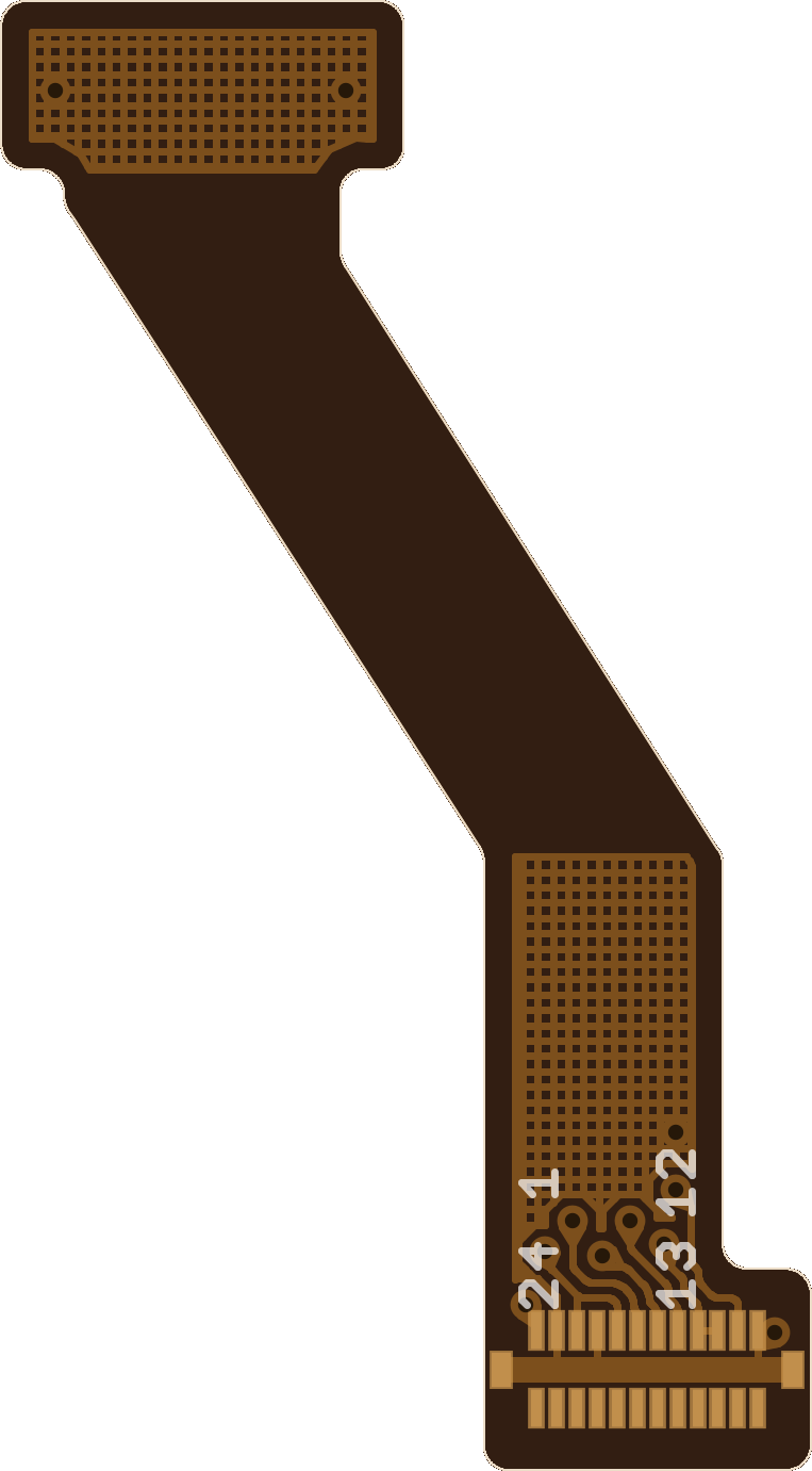
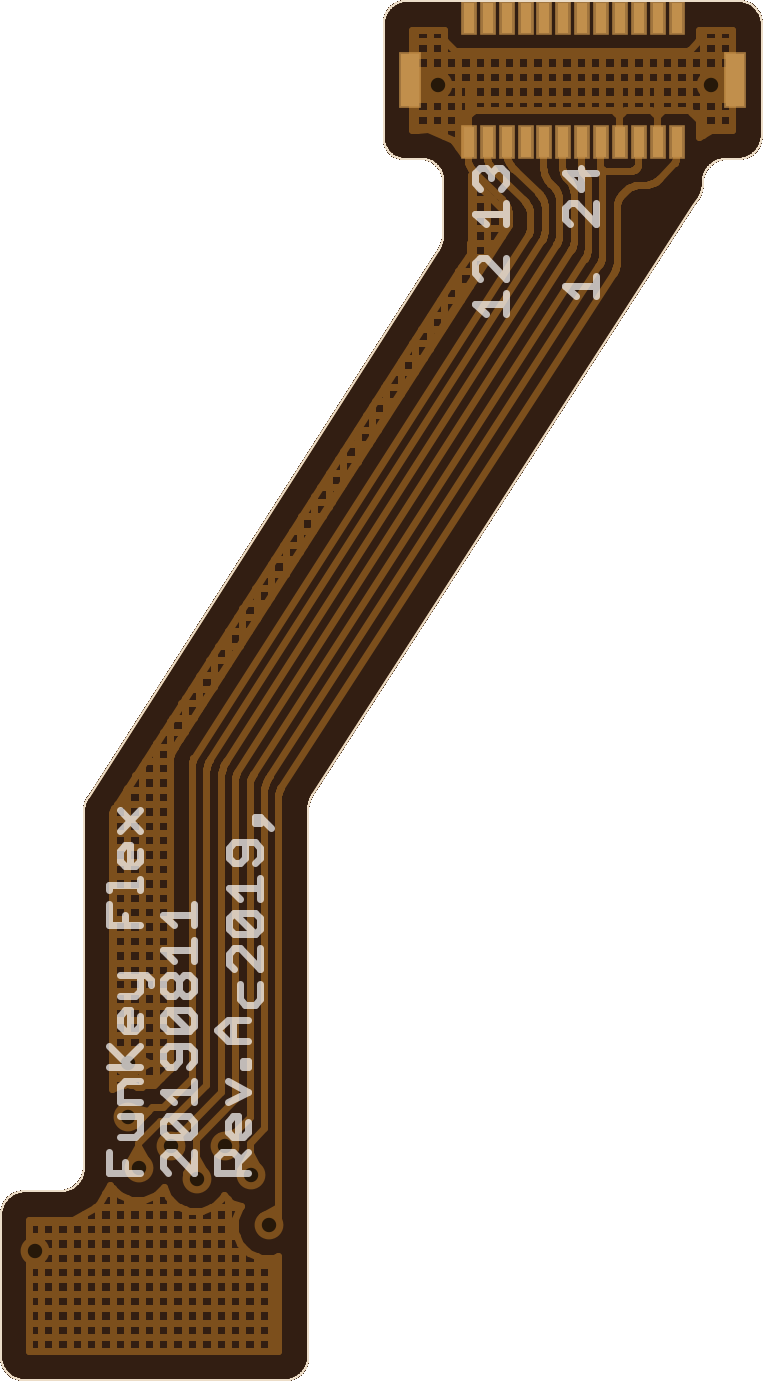
    Here are the corresponding layouts:

  • Layout: Screen FPC Extender

    Squonk4208/12/2019 at 21:11 0 comments

    LCD Screen

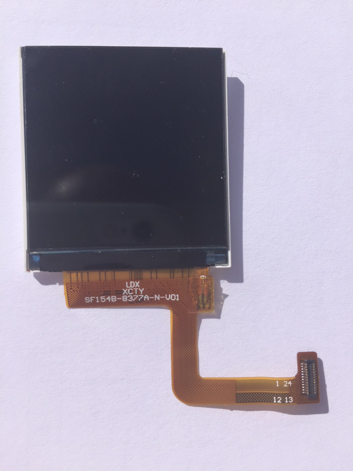
    The chosen LCD screen for the FunKey console is awesome:

    Hinge

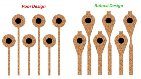
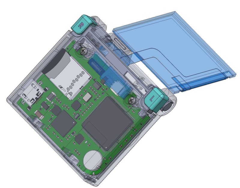
    The FunKey console uses a foldable design in order to reduce the device size when not in use, and maximize both the screen and keypad size when playing. The screen flat cable must then go into the hinge, and in order to avoid too much stress that would eventually lead to broken cables, it must be "rolled" into it like a flypaper in order to divide the stress over the longest possible length.

    Unfortunately, the stock LCD screen ribbon cable is not long enough. This is of course something that the manufacturer can customize, but this costs a fixed tooling fee of $800... We plan to go this way for mass production, but this sounds like a lot of money for the prototyping phase only.

    FPC Extender

    So, we decided to use cheaper alternatives for our prototypes:

    • for the Revision A, we used individually soldered thin enameled copper wires and an ultra small PCB placed into the hinge: definitely not something to use for more than 2 boards!
    • for the Revision B, we decided to invest some money into a customized FPC (Flat Printed Cable) as we can get 5x FPC prototypes for ~$100 at PCBWay

    The problem is: I never designed FPCs before ;-)

    I got some basic hints from one of my colleague:

    • the copper density must be as constant as possible
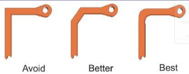
    • the traces must use smooth curves instead of sharp angles to avoid tearing during flexion

    However, a few questions remained unanswered:

    1. what material and thickness to use for the stiffeners?
    2. what material and thickness for the flex itself?
    3. which stack-up?

    I decided to crawl the Web for more information, and here is what I found, I hope this may help some other PCB designers:

    Stiffeners

    Stiffeners are used over some parts of the FPC cable for various reasons, and I found this page very informative. Basically:

    • stiffeners in FR4 (epoxy) material are added below components to protect solder joints: this is exactly what we will need for our connectors!
    • stiffeners in polyimide (yes, this is the famous "PI" acronym that you meet everywhere, including on the SAEF screen datasheet!) are used to bring thickness to a given value in order to meet the ZIF (Zero Insertion Force) connector requirements
    • aluminum or metallic stiffeners are used as heatsinks in order to dissipate temperature from power components

    The stiffener thickness is variable, but is generally between 0.2 mm and 2 mm. I chose FR4 stiffeners with a 0.2 mm thickness as it is the thinnest, but also because this is the thickness for the original SAEF screen stiffener, too.

    Flex

    For the flex cable itself, I found this slideshow containing a lot of details.

    I learned that:

    • a flex is made up of Polyimide ("PI", aka Kapton which is a trademark from DuPont)
    • Pyralus is another trademark from DuPont for the sandwich including the PI film, the glue and copper laminate, the glue and the PI "Coverlay" (for "Coating Overlay")
    • the copper can be in rolled Annealed ("RA") form, or obtained by electro-deposition ("EP"), the former being more common and cheaper
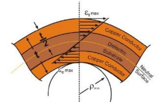
    • for a single or double-sided flex, the minimum bend radius is 6x the total thickness, 12x when using more layers
    • indeed, using curved traces is better that sharp-angled ones!
    • vias should feature "teardrops" to avoid problems with the larger drill / copper / coating registration tolerances for FPCs
    • a hatched ground plane is recommended in order to reduce weight and increase flexibility

    With all these elements now clear, I decided to use PI with rolled-annealed copper foil ("RA") to reduce costs.

    Stack-Up

    For the layer stack-up and dimensions, I found these...

    Read more »

  • Meet the team

    c.Invent08/12/2019 at 09:00 0 comments

    I tried different angles to approach this log, and writing about us from a third person's point of view simply wouldn't work. It was too detached for my taste and it felt hypocritical writing things about myself as another's POV. Instead I chose the 1st person narrative to talk about our team, "I" meaning "Vincent" in this case. It feels more genuine, and I get to really "tell" our story this way.

    FunKey's project is currently composed of three people which, by order or arrival in the team, are: Vincent (myself) Michel and David. Since we are a small team, the best way to present all of us is simply through FunKey's story, so here it goes:

    Vincent

    As some of you may know Funkey started out as a project submitted during the 2017 Hackaday Prize called Keymu. Before explaining why I undertook such a project, let me quickly go over some of my background. 

    Originally, I studied telecommunications during my master's in France. Telecommunications is a vast topic that encompasses many areas such as informatics, electronics, networking, signal processing... I specialized in the latter, and during my last year abroad, I quickly drifted towards computer vision, a topic that never ceases to amaze me. After the master's, I actually continued in this branch during my PhD. 

    So, yeah, I was a research scholar, in Computer Vision and Machine Learning at the time, pretty far from electronics... 

    Something always felt missing though, all this high-level knowledge felt shallow without the low-level one. Computer vision is often used on embedded products, allowing them to "see" the world and understand it for us, faster than us. I simply felt the need to know how to build the machines for which we developed these algorithms, in order to understand the whole chain. After my PhD then, I started working as an embedded engineer for a company in France. This is where I met Michel and David for the first time. 

    When, a few months later, Hackaday published an article about SpriteTM's tiny console, it was love at first sight. I wanted very badly to build one, not just to own it but because it called to my inner retro-gamer instincts and it was a great way to learn about electronics and embedded software. At the time SpriteTM did not release yet any of the code or designs, hence Keymu was born.

    I quickly realized, I undertook something way bigger than expected for a first "side project". It was completely different than SpriteTM's design: it was based on a computer module, I needed to develop a custom linux distribution (very different code than for microprocessors, especially the drivers), the mechanical hinge was harder than expected...This is when Michel entered into play. 

    Michel

    It is safe to say that Keymu might have never hatched without him. Apart from helping me with the electronical design, every roadblock I met seemed only small bumps before his incredible experience. He followed the design and all the new ideas from the start, started himself installing the environment for developing the Linux distribution with Yocto, proposed solutions to many encountered problems... All in all, he was already part of the team from the start, he apeared only "officially" in the team during our next project: FunKey Zero but it is simply formalities.

    For the purpose of this log, I have asked my partners to present themselves through small bios. Since I started this first narrative point of view, it feels only logical to keep it throughout the log, that is why I prefer to restranscribe their bios as they've been provided. 

    Here is Michel's:

    I started my engineering experience at age 2 (back in 1968) by inserting...
    Read more »

  • FunKey Revision B is out and ordered!

    Squonk4208/04/2019 at 17:55 0 comments

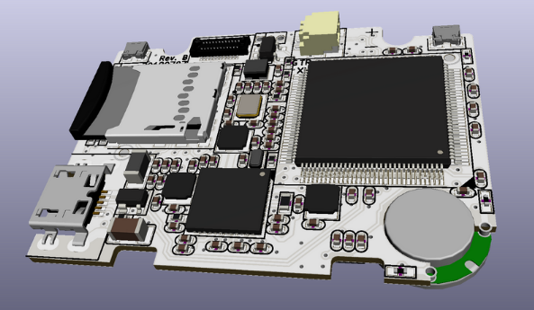
    The FunKey Revision B is eventually out!

    You can download the corresponding design file ZIP and schematics in PDF from the "File" section.

    FunKey Revision A Board

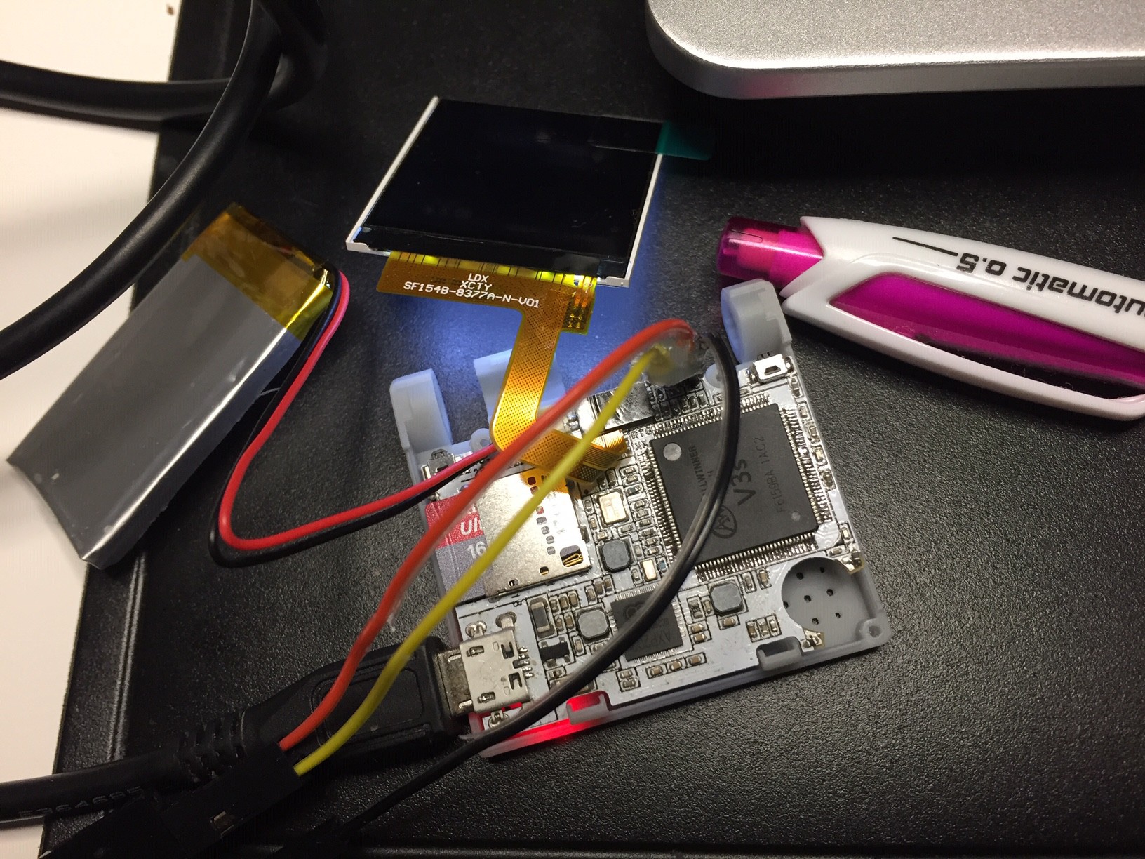
    We consider FunKey Revision A board as an "alpha test" board. We built 2 units using manual pick & place and a small T962 reflow oven.

    Except for a few bad solder joints, the only real problem we encountered is a wrong value for the R11 DDR RAM equalization resistor (was 240k instead of 240R). Another minor problem was a wrong footprint for transistor Q1 (was SOT323 instead of SOT23)

    We can consider it as a success, as the boards worked (almost) out of the box and we were able to mount them into a 3D-printed case and make some nice videos out of them.

    However, assembling this board manually doesn't scale up very nicely: as these are dual-sided PCBs, the boards needs to go twice in the oven, using solder paste with different reflow temperatures, and just placing the 175 components on each board takes hours and a lot of patience...

    We thus decided to move to...

    FunKey Revision B Board

    The goals for this revision were:

    • correct the Revision A bugs
    • make some mechanical adjustments required to ease the FunKey assembly into the case
    • replace some components to reduce the BOM cost
    • add test pads for a better testability
    • outsource the PCB Assembly (PCBA)
    • avoid over-engineering a working board!

    Bug Corrections

    As discussed above, the only physical changes were to replace the value for the R11 DDR RAM equalization resistor (was 240k instead of 240R) in the BOM and to change the footprint for transistor Q1 (was SOT323 instead of SOT23).

    A few quirks in the schematics were corrected:

    • the "START" and "SELECT" signal labels were swapped (now also renamed to "START" and "FUN")
    • the comment for R8 was referencing the wrong chip (U2, now U3)
    • some signal labels around U5 were not the same size as all other labels

    Mechanical Adjustments

    Although we were able to mount the Revision A PCB into the 3D-case, we found some minor assembly problems:

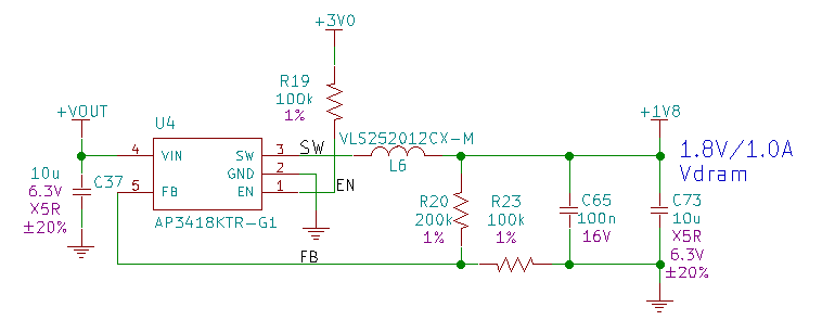
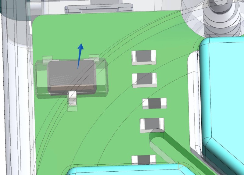
    • the 1.5 mm headroom over the PCB button side was too low over some components (the power inductor L6 and the transistor Q1): L6 has been moved to the other PCB side with all components for the DRAM Power, and the Q1 transistor was moved away from the buttons
    • the screen connector has been moved to be in front of the hinge flex opening and turned 180° to expose all the active pins to on the PCB edge side
    • consequently, the UART and battery connectors have been shuffled around, and the battery connector moved away from the screw well to provide more room to bend the battery wires
    • the 2x Omron B3U-3000P(M) rear buttons have been replaced because they were too fragile and did not provide a good feedback when pressed. We now use 2x Panasonic EVP-AVAA1A, which are the right-angle equivalent of the EVP-BB2A9B000 we have for the top buttons. These buttons are backed by the PCB edge so they have no chance to break if pushed too hard, and their haptic feedback is really good
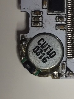
    • the speaker mounting was tedious: we tried to avoid having to solder wires, but the PCB thickness of 0.8 mm was too important to provide a way to bridge the gap between the trace and the speaker pad with a solder blob, we had to use some TH resistor wire to do the connection:
      We changed the design to use castellated pads ("half-moon" plated holes on the PCB edge) positioned farther just over the speaker pads, so the distance between the PCB copper pad and the speaker pad is now zero and allows soldering the speaker with just a small solder bridge

    Component Sourcing

    The FunKey Revision A board used mostly components available from major online distributors, ( we ordered them from Mouser,...

    Read more »

  • FunKey gets social ! (Website, newsletter and social networks)​

    c.Invent07/15/2019 at 12:55 0 comments

    The Funkey team is proud to announce FunKey's official website

    We have also setup a newsletter to start building a community and keep everyone informed about FunKey's updates and most importantly its release date. You can subscribe to the newsletter directly on the website.

    Official web site : http://www.funkey-project.com

    Also, we have settled on a date for the crowdfunding campaign: Q4 2019 on KickStarter.

    Again: don't hesitate to subscribe our newsletter directly on our website !

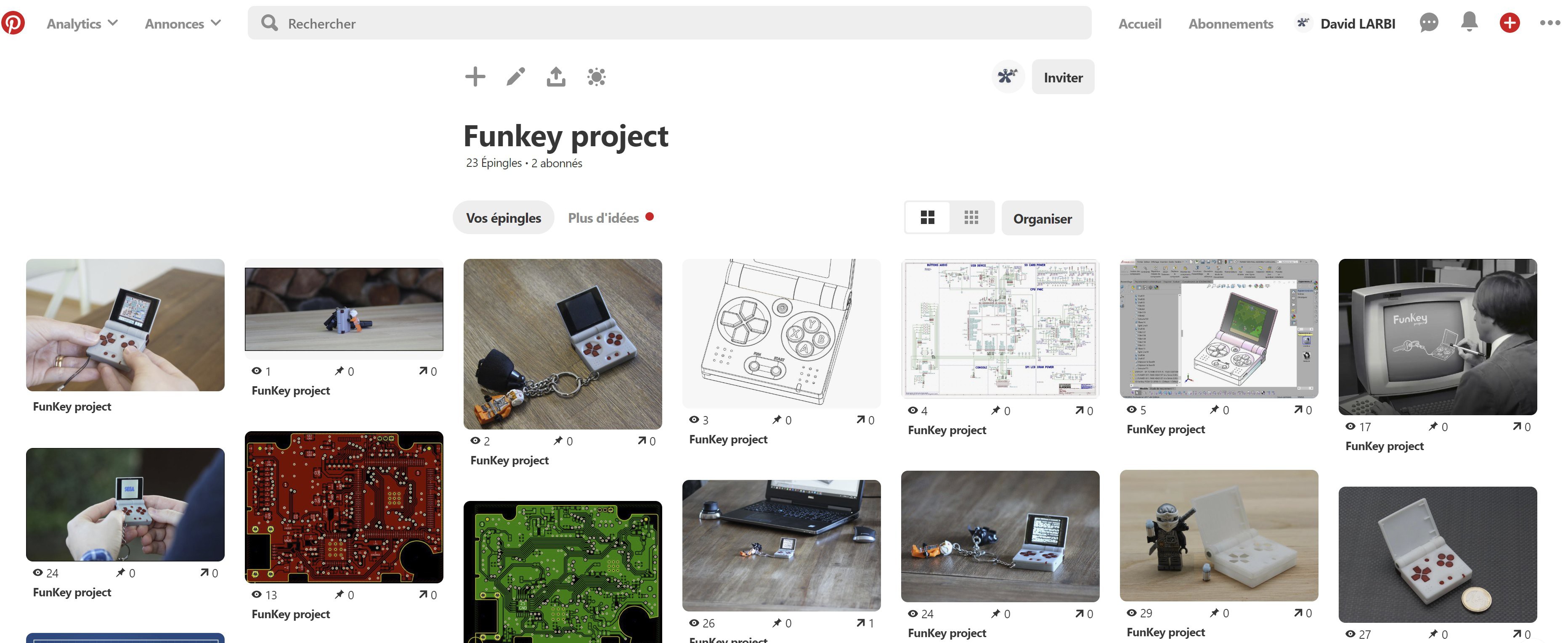
    You can also follow us on our social media pages:

    Twitter

    Facebook:

    Instagram:

    Pinterest

    Youtube

    Grabcad

    Thingiverse

  • FunKey vs. RPi Zero

    Squonk4205/29/2019 at 21:15 0 comments

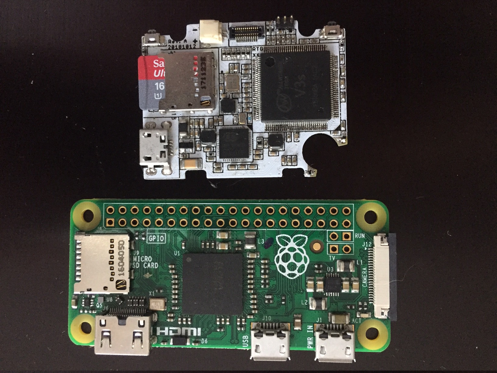
    Can you spot what the 2 boards have in common?

    They are both small, but this is not the only common point...

    • It is not the HDMI  connector (FunKey doesn't have HDMI output),
    • not the USB connectors (FunKey has a low-profile PCB edge mid-mount model),
    • not the CSi camera interface (FunKey does not have it either, although its CPU has this capability)
    • CPU is of course different, since the RPi Zero BCM2835 is not available for retail
    • DRAM integration? Yeah, but not quite: the RPi has a PoP( Package on Package) Elpida B4432BBPA-10-F 4GB DDR2 DRAM, the FunKey has an unknown SiP (System in Package) 512MB DDR2 DRAM

    ... Yes it is: the microSD Card connector! Both boards are equipped with a Molex ref. 104031-0811.

    It is a pure coincidence, though. Our primary motivation for choosing this (rather expensive) connector was its low profile: only 1.42 mm height, whereas most common connectors are ~1.9 mm height. And overall size too: only 11.95 mm x 11.40 mm, while common ones are more in the 14.70 mm x 14.50 mm ball park.

    It is just a simple manual "PUSH/PULL" type (i.e. no bi-stable "PUSH/PUSH" mechanism that would take more space), but we don't care, as in the FunKey, the micro SD card is not meant to be removed anyway.

  • Schematics: Power

    Squonk4205/21/2019 at 17:45 0 comments

    Capacitor Usage

    So far, we already encountered capacitors for many different usages:

    Load Capacitors

    We have seen load capacitors used with the 2 crystals in the discussion about CPU.

    A quartz crystal always provides both series and parallel resonance, the series resonance being a few kilohertz lower than the parallel one.

    Crystals below 30 MHz like ours are generally operated between series and parallel resonance, which means that the crystal appears as an inductive reactance in operation, this inductance forming a parallel resonant circuit with externally connected parallel "load" capacitance. Any small additional capacitance added in parallel with the crystal pulls the frequency lower in the range between the series and parallel resonance frequencies, insuring crystal startup and stable operation.

    For modern circuits, these load capacitors have a typical small value < 20 pF.

    Bulk Capacitors

    Bulk capacitors are used to prevent a power supply from dropping too far during the periods when current is not available. At the same time, they help to reduce the power supply voltage ripples by smoothing their output voltage.

    Many such capacitors are used at both the input and output of the numerous linear and switched mode power supplies in the PMIC discussion

    The main bulk capacitor value is generally high (some µF), but there may be smaller parallel capacitors added for stability.

    Coupling Capacitors

    As you probably know, capacitors are made of 2 parallel conductive electrodes separated by a (thin) isolating dielectric material (even if these electrodes are rolled or layered to reduce the component size). Thus by construction, no DC (Direct Current) can flow from one electrode to the other, but by influence using the electric field, AC (Alternative Current) still can go through. This is how coupling capacitors are used to link 2 circuits while removing any DC bias voltage on one side or the other of the capacitor.

    We use such a coupling capacitor in the Audio schematic description for feeding the audio power amplifier from the CPU audio output.

    Filter Capacitors

    We have seen many examples where capacitors are used within passive filter circuits along with resistors or inductors, mainly to remove unwanted frequencies from a power supply or a signal.

    Decoupling (Bypass) Capacitors

    We have already seen some decoupling capacitors when looking at the buttons circuit.

    Active components such as transistors and chips are connected to their power supplies through conductors featuring a (small) common impedance made up of complex (resistive, capacitive and inductive) value. Because of these parasitic components, a device that suddenly draws some current in spikes will generate a drop in its voltage power supply. If many devices are sharing the same power supply and impedance, the state of one device will be coupled to the other ones through the common impedance of the power supply conductors and may affect thir operation.

    In order to decouple the devices, capacitors placed as close as possible to the device power supply input pins are used, which act as local energy storage. These capacitors are also named "bypass capacitors" as they shunt transient energy from the power supplies past the device to be decoupled, right to the GND return path.

    There may be different capacitors values placed on the same power supply pins in order to filter transients at different frequencies: the bigger the capacitor value, the lower the frequency. A typical value is 100 nF, and values from 1 µF to 10 µF are used for lower frequencies and / or higher current draws, while lower values of a few nF are used for filtering higher frequencies.

    In essence, decoupling capacitors are not very different in their function from bulk capacitors: the only difference is one of scale, both of current and of transient duration. Bulk capacitors deal with large currents and periods of 10s of ms, whereas decoupling capacitors are used for...

    Read more »

  • Schematics: SD Card

    Squonk4205/19/2019 at 10:15 1 comment

    The FunKey game console uses the SD Card both as its boot device and its only storage device, so a good operation of this interface is absolutely mandatory.

    The Allwinner V3s provides 2x 4-bit MMC / SD Card / SDIO interfaces. In the FunKey, only interface #0 is used.

    If you look on the Web, you will find many contradictory SD Card interface designs, with a combination of pull-up / pull-down resistors, ESD devices and power supply filtering, with all pins wired or not, such that it is very difficult to know what is really required. To better understand the situation, we need to go back to the specifications.

    Specifications

    The SD Card physical interface is provided in the "SD specifications, part 1, Physical Layer Specification version 2.00, May 9, 2006", for which a simplified version is available here.

    The MMC phyiscal interface can be found in the "Multi Media Card System Specification version 4.3, JESD84-A43, November 2007", available here (registration required).

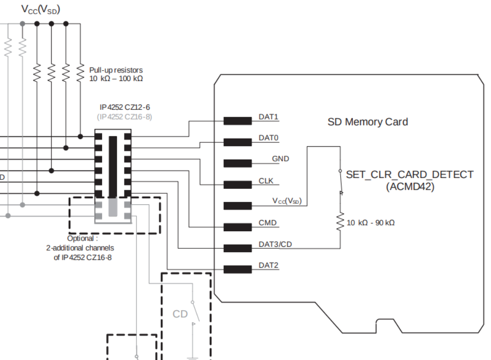
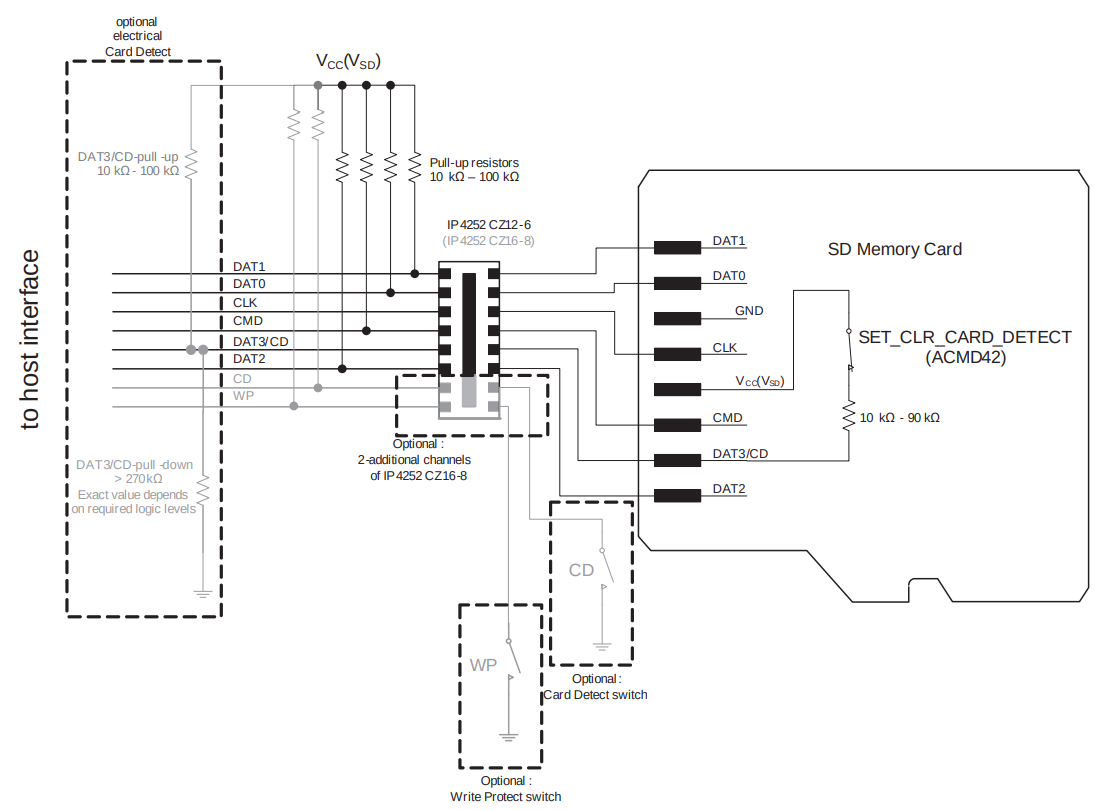
    But a good summary of the requirements is given in the "AN10911 SD(HC)-memory card and MMC  Interface conditioning" application note from NXP, from which this schematic is taken:

    Note: This schematic does not include details concerning card-supply and typical power-supply decoupling capacitors.

    Write Protect (WP)

    A write protect mechanical switch is provided in the full-size SD Card, but not in the mini or micro SD Card form factor. As we plan to use a micro SD Card only, it is not used for the FunKey, along with its pull-up resistor and ESD protection.

    Card Detection (CD)

    As the SD Card is required to boot the FunKey, is always inserted and opening the device is requried for its removal, we don't need the optional card detect mechanical switch feature (even if the chosen connector provides it) and its related pull-up resistor and ESD protection.

    The SD Card specification provides another mean to detect the card using a card built-in pull-up resistor on its DAT3 signal, that can be later disconnected during normal operation using he SET_CLR_CARD_DETECT (ACMD42) command. In order to correctly detect if the card is inserted, a high value external pull-down resistor (> 270 kohms) is required to drive the detect signal low when no card is inserted, while the card built-in 10-50 kohms resistor will drive this signal high when inserted.

    However, this feature is not compatible with MMC cards, so its usage should be avoided and the mechanical detection is preferred.

    Pull-Up Resistors

    Both the SD Card and MMC specifications require not to leave the interface signals floating, except for the CLK signal, where a pull resistor would cause significant signal distortion because of the required high speed and short rise/fall times. OTOH, it is recommended to add a series resistor on this CLK signal as close as possible to the clock source (the CPU) to avoid ringing, as we already discussed it in the log about the CPU.

    Hopefully, the Allwinner V3s CPU provides internal pull-up resistors for all these signals, so we don't have to add external pull-up resistors. These resistors are given with a typical value of 100 kohms (50 min, 150 max). Unfortunately, the CMD signal for MMC card features an open-drain output mode, and its value should be undercut (down to 4.7 kohms) to guarantee a sufficiently short rise time in this mode.

    Schematics

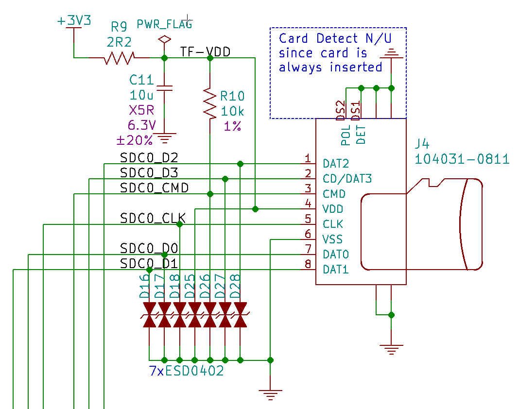
    The FunKey SD Card interface schematic is the following:

    Even if in the FunKey device the SD Card and its connector are not accessible without opening the enclosure, there may be some situations where the user may decide to do so. We thus attach an ESD protection TVS diode (D16, D17, D18, D25, D26, D27, D28) on each signal to avoid any ESD hazard.

    As discussed above, a single pull-up resistor R10 is used on the CMD signal for MMC compatibility.

    The micro SD Card connector built-in card detection switch is not used, since the card must always be inserted for the FunKey to boot,...

    Read more »

View all 26 project logs

Enjoy this project?

Share

Discussions

Samuel David wrote 05/15/2023 at 16:15 point

Hi there ! Great Job , its very i want to use this on my website https://faceitfinder.com/

  Are you sure? yes | no

baicker.009 wrote 04/07/2022 at 02:04 point

good job

  Are you sure? yes | no

singhm081085 wrote 02/06/2022 at 05:31 point

Wow I orginally saw keymu back in 2017.  I logged back in today and saw it and it led me here.  You guys have come a long long way.  Amazing.  I might have to buy because it's gotten too complicated for me to build my own.

  Are you sure? yes | no

utopcell wrote 06/20/2020 at 07:04 point

This is a fascinating project and the build log is by far the most detailed I have seen on an open-source project. I am very curious how you prototyped the part that sits on top of the LCD. Is it actual glass ?

  Are you sure? yes | no

seilerjacinda925 wrote 11/19/2019 at 15:34 point

Hi

Nice to meet you after viewing your profile i am Jacinda, from (jakarta) indonesia,

i have a project discussion with you please email me on: (jacinda.seiler@yahoo.com)

  Are you sure? yes | no

PixelDud wrote 05/04/2019 at 02:58 point

What is the top center button for?

  Are you sure? yes | no

David.Larbi wrote 05/04/2019 at 05:55 point

It's power on/off button. why here ; to protect it when the console is closed on the keychain.

  Are you sure? yes | no

PixelDud wrote 05/04/2019 at 15:08 point

Is that also what it was for on the GBA SP?

  Are you sure? yes | no

Squonk42 wrote 05/04/2019 at 18:31 point

This button was a "Screen Light On/Off" switch on the GBA SP:

https://www.nintendo.com/consumer/downloads/agsmanual_english.pdf

  Are you sure? yes | no

PixelDud wrote 05/04/2019 at 18:53 point

@Squonk42 Thanks.

  Are you sure? yes | no

J. Ian Lindsay wrote 05/04/2019 at 00:37 point

Ha! This is awesome! And timely, because I need such a screen.

  Are you sure? yes | no

DeanChu wrote 04/25/2019 at 04:13 point

Amazing design!!! Start to follow you guys from the funkey zero project and this one is THE game console in my dream. Can't wait to buy one.

  Are you sure? yes | no

Squonk42 wrote 04/25/2019 at 08:53 point

We made a lot of improvements since then!

Patience is still required, in the meantime you can read our logs and check our files to see our progress!

  Are you sure? yes | no

Paul Berkley wrote 04/24/2019 at 15:55 point

As dumb as it sounds: Take my money! I need this in my life!!!!

  Are you sure? yes | no

c.Invent wrote 04/24/2019 at 15:58 point
Sounds  perfectly fine to me ;)

A bit of patience is still required though, but it's coming!
  Are you sure? yes | no

Paul Berkley wrote 04/24/2019 at 16:04 point

I will be patiently watching and waiting

  Are you sure? yes | no

Papá Tortilla wrote 04/18/2019 at 23:26 point

Any chance of start selling them?

  Are you sure? yes | no

Squonk42 wrote 04/19/2019 at 07:12 point

FunKey is still under heavy development, but we plan to make it available to the public as soon as the team can have it ready!

Our participation to the Hackaday Prize 2019 is a good way to boost this project to turn it from a concept into an industrialized product.

  Are you sure? yes | no

Shranav Palakurthi wrote 04/17/2019 at 15:08 point

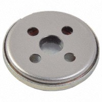
Have you thought about using a piezo speaker/buzzer? Should be cheaper and waaaay thinner (sacrificing a little bit of audio quality). For chiptunes, though, it should be fine.

  Are you sure? yes | no

Squonk42 wrote 04/17/2019 at 15:39 point

You are right, piezo speakers/buzzers are much thinner, but they have a larger diameter too, so they can only be placed on the bottom side.

Piezo speakers/buzzers are driven using PWM signals, which we currently don't know how to generate on the V3s using the ALSA API ;-)

And if audio quality is OK for the oldest consoles, it may be too limited for the most advanced ones like the GBA, Genesis or PS1.

  Are you sure? yes | no

Shranav Palakurthi wrote 04/17/2019 at 16:14 point

You bring up some good points. Keep up the great work!

  Are you sure? yes | no

Similar Projects

Does this project spark your interest?

Become a member to follow this project and never miss any updates