 Walter
The main PCB board will be kept, as it holds the case together. There are three plug-in modules that will be removed. On it are logic chips (some AND/OR gates and many flip-flops). Looking at the six small boards with the nixies, it becomes clear that these must remain, to hold the nixie tubes in the correct position. I cannot read the part number on the nixies but they seem to be ZM1082's. Looking at the way they are wired, it looks pin-compatible with the ZM1082 at least (pin 13 is the anode).
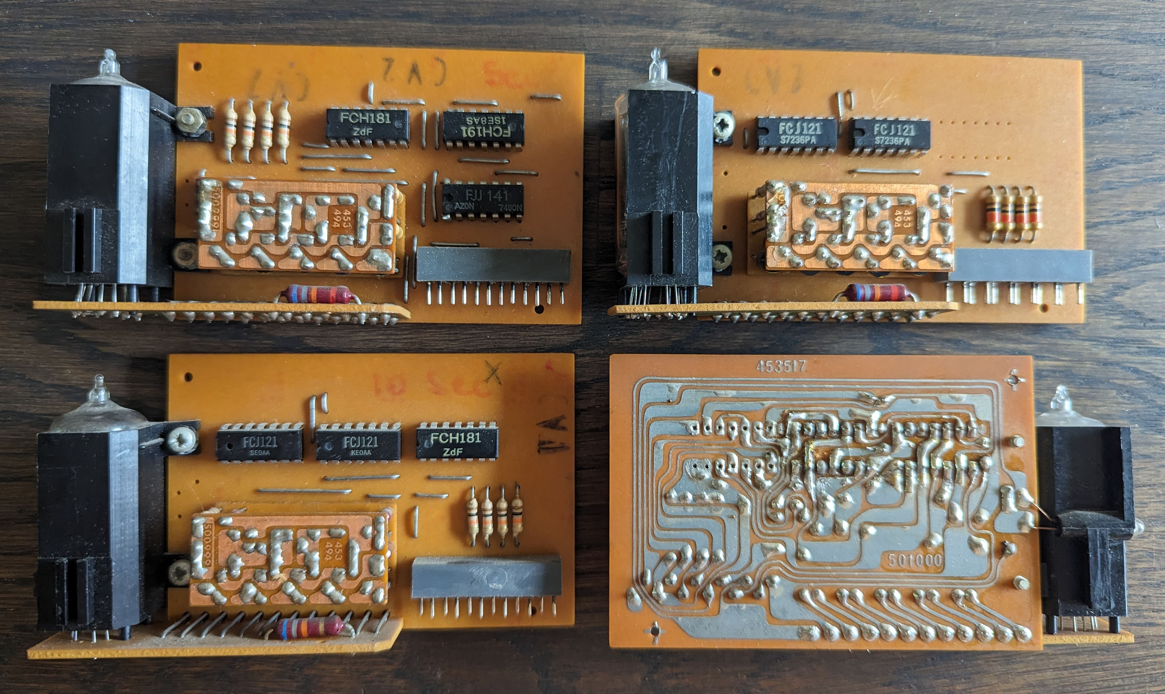
There are three different types of nixie boards but I think they are compatible. Two of the six boards have an additional little neon tube to act as a dot (see bottom right board in the picture). These, I can probably repurpose for my clock.
The TTL chips use the Mullard numbering (FC series) and seem to be sourced from different manufacturers. There's a few with a date code I can recognise: week 36 of 1972. Half a century of age on this thing!
I will cut the traces on the PCB and solder new wires on to just drive the nixie tubes and decouple the rest of the electronics on there.
Discussions
Become a Hackaday.io Member
Create an account to leave a comment. Already have an account? Log In.
That module under the TTL ICs in the photos might hold the decoder and drive transistors and convert some sort of binary or biquinary code from the IC counters and gates to 1 of 10 cathode drives. You might be able to remove the TTL ICs and feed the decoder from some sort of shift register and reduce the amount of wiring you have to take to each nixie board.
Are you sure? yes | no
Yes - it looks like that. I'll add a picture in the next posting.
Are you sure? yes | no