 Walter
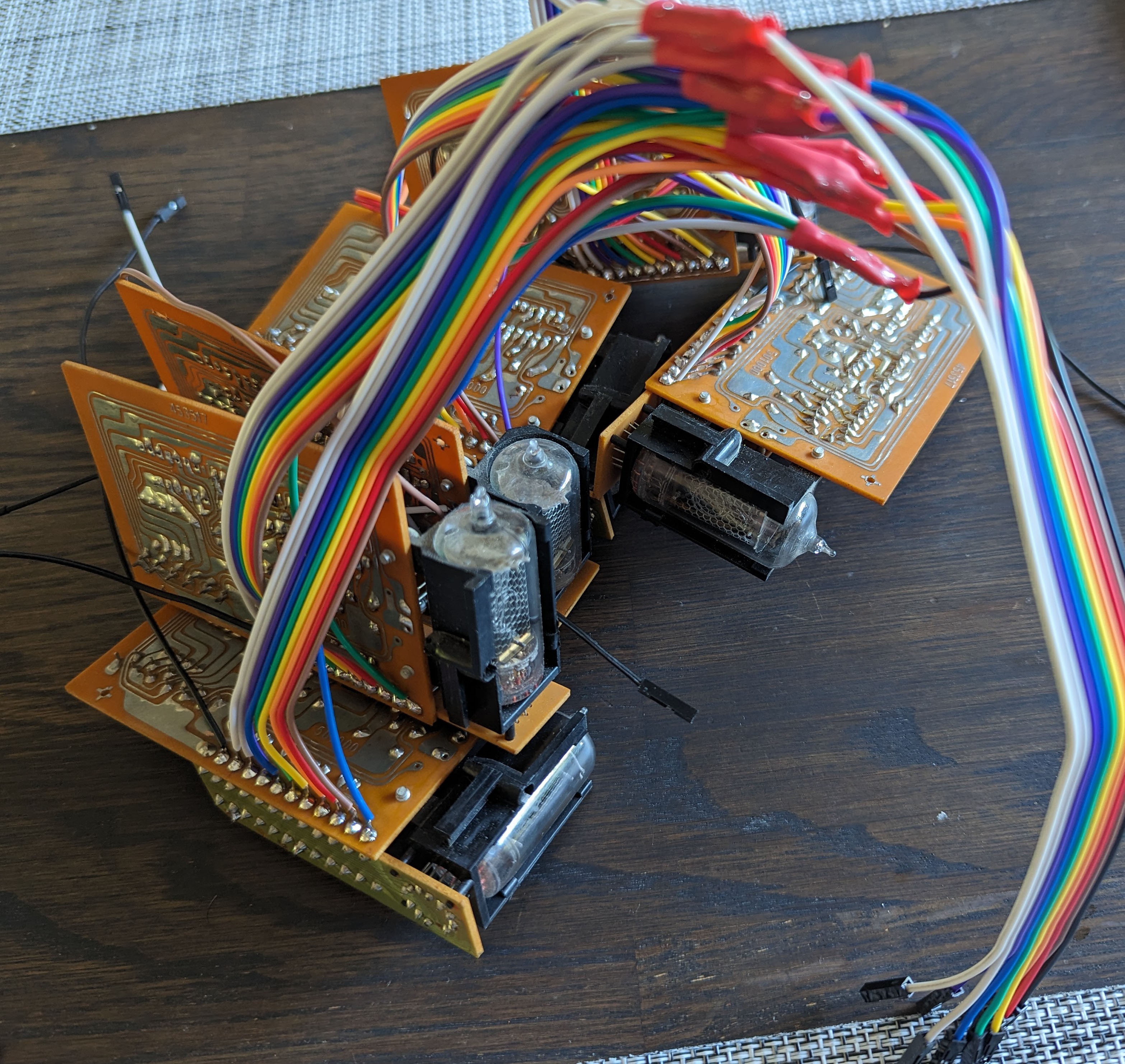
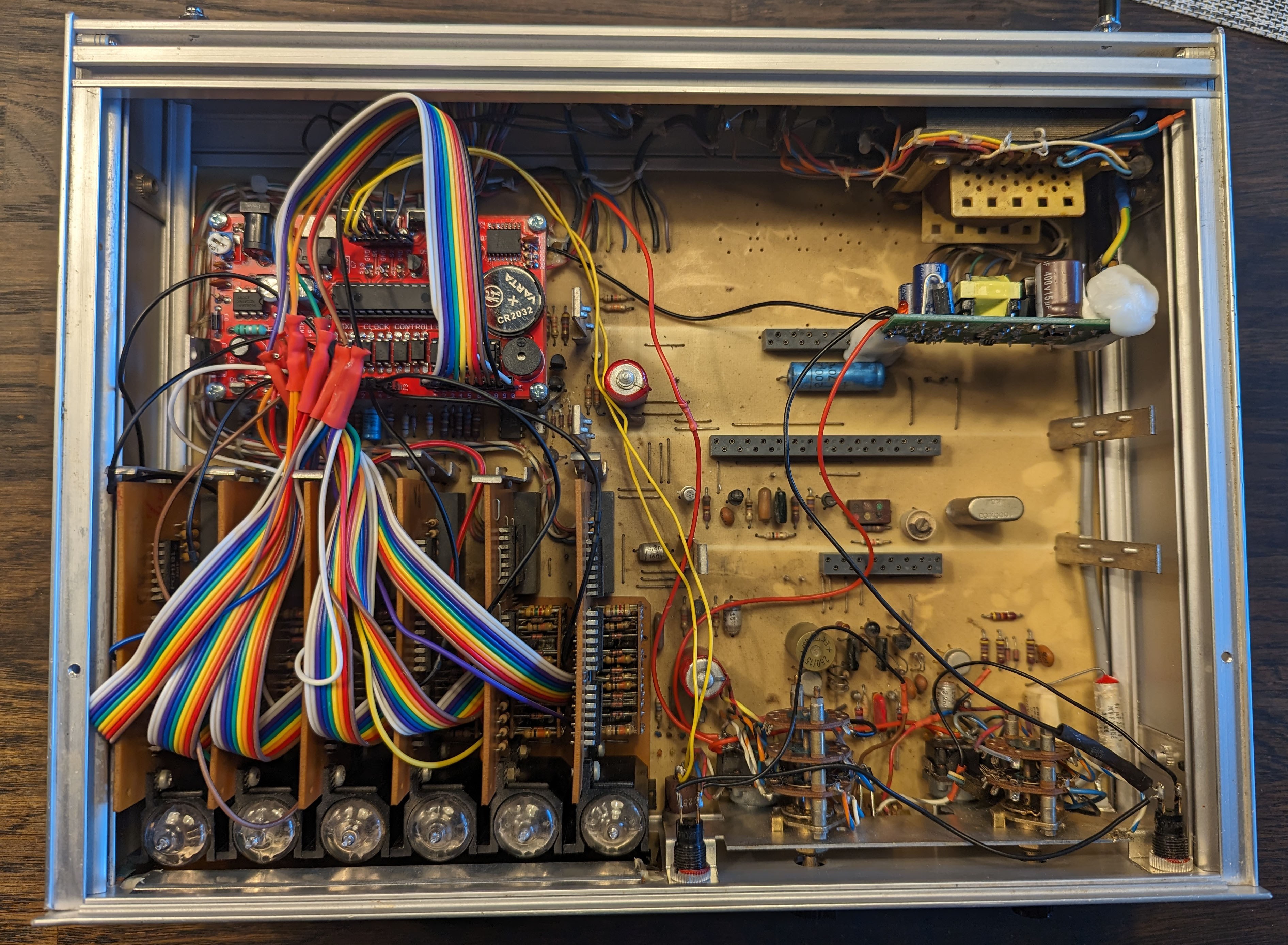
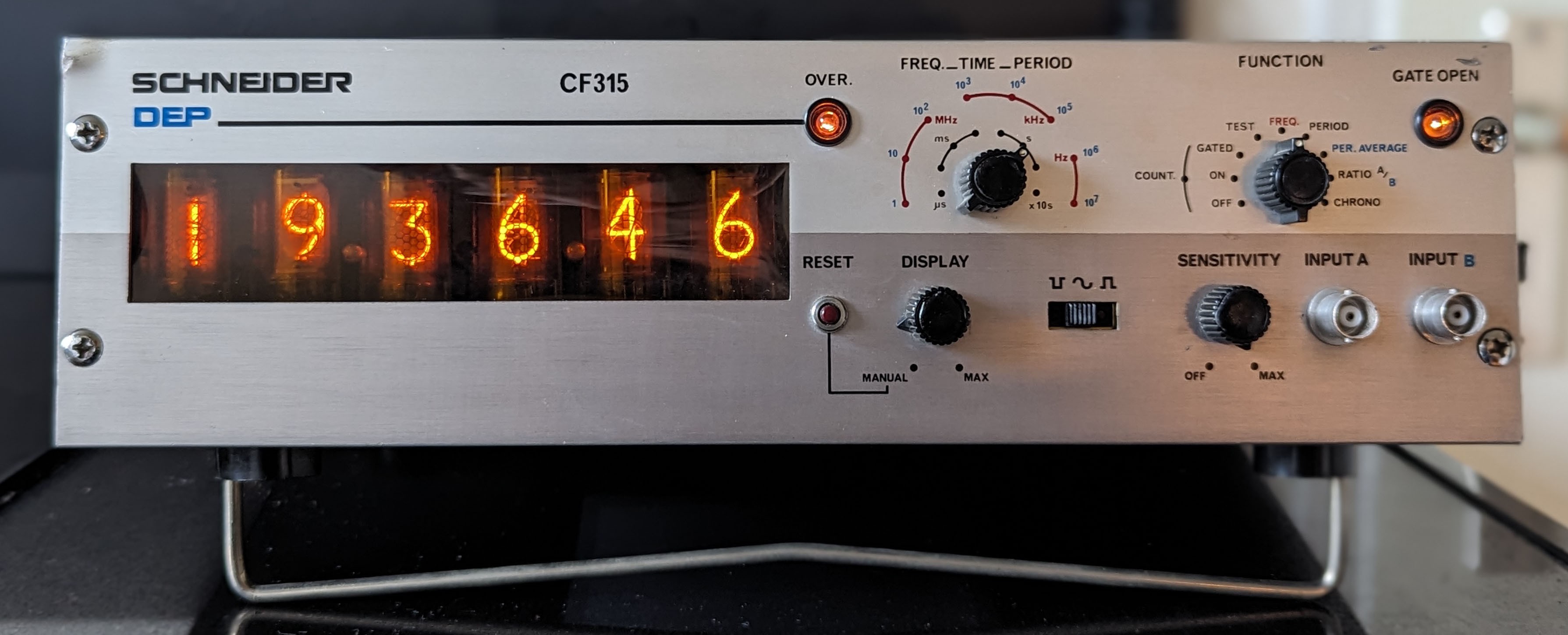
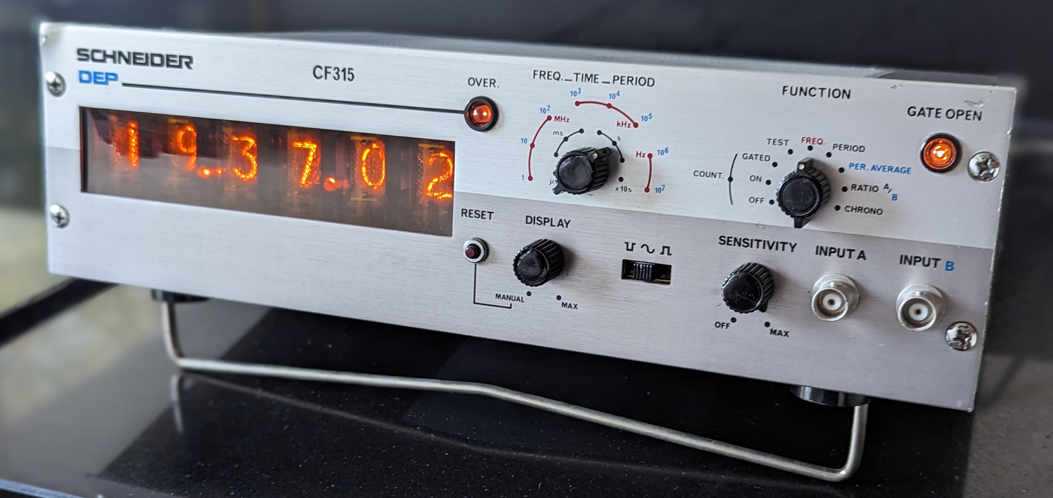
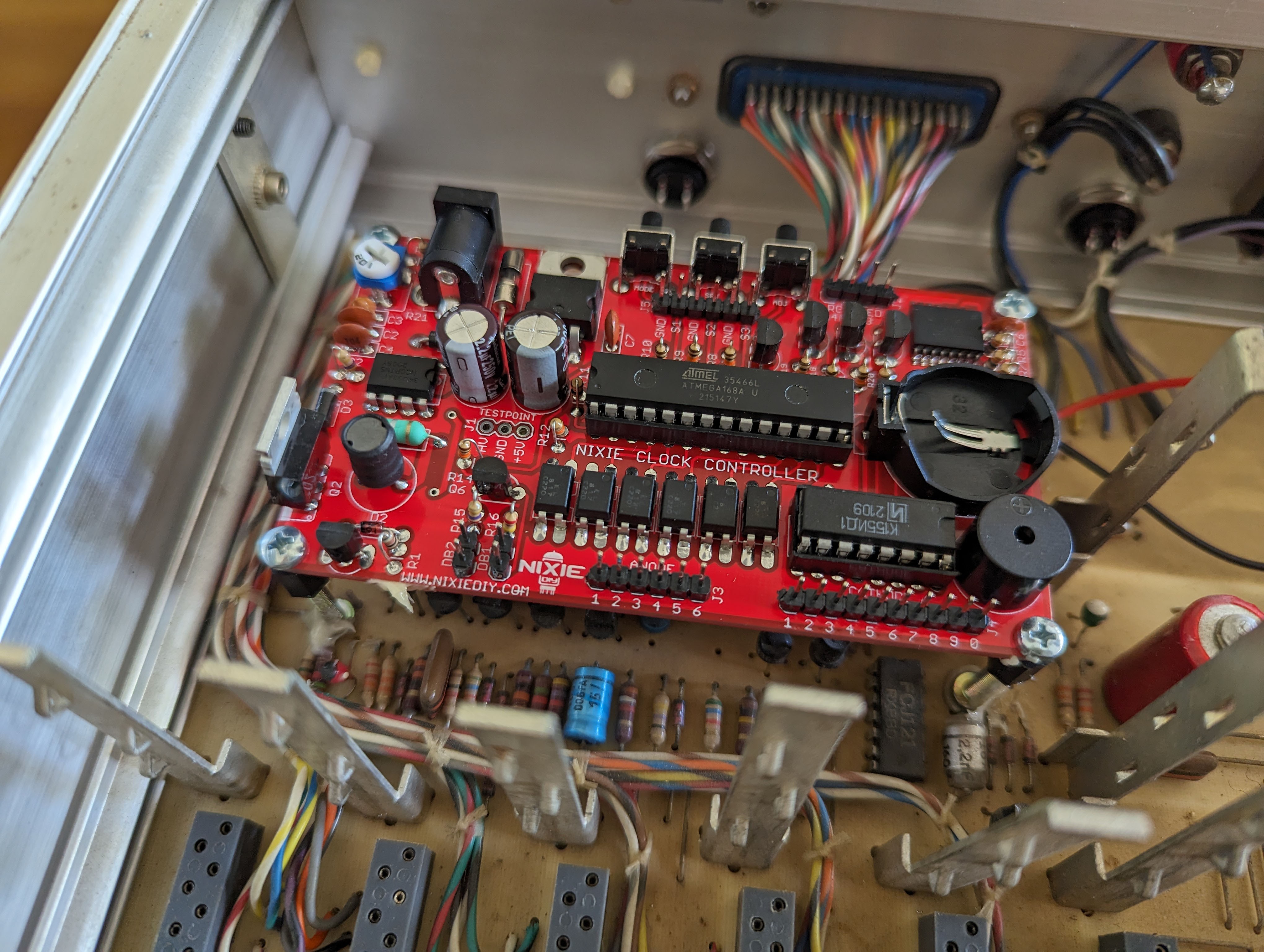
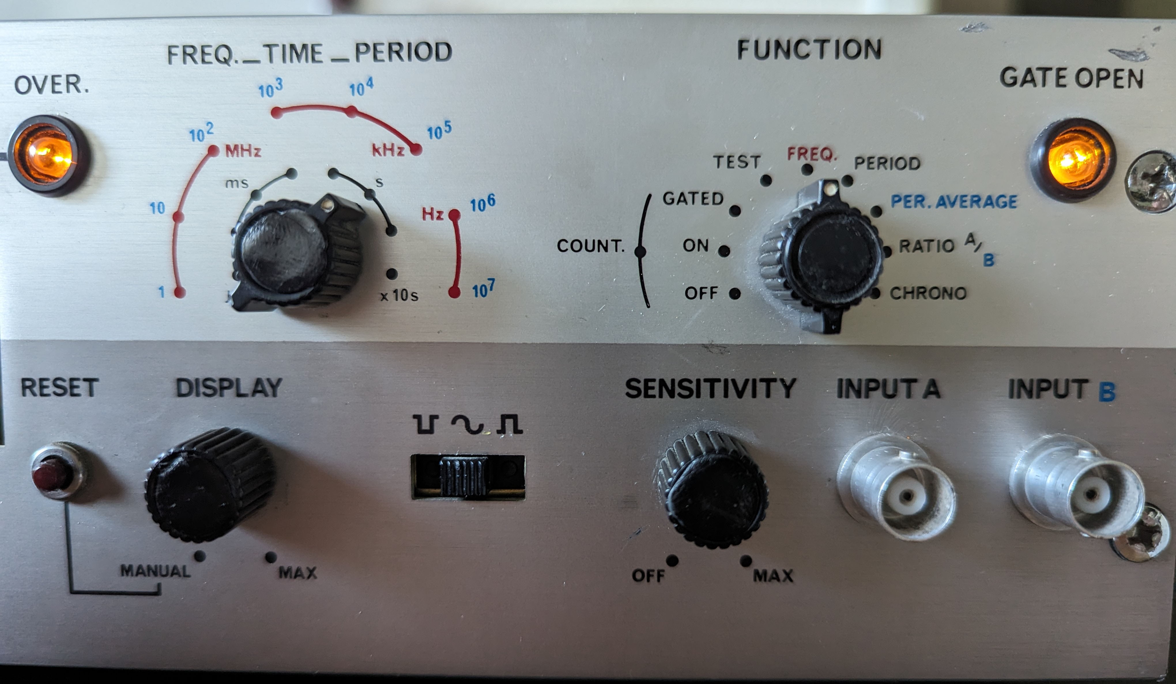
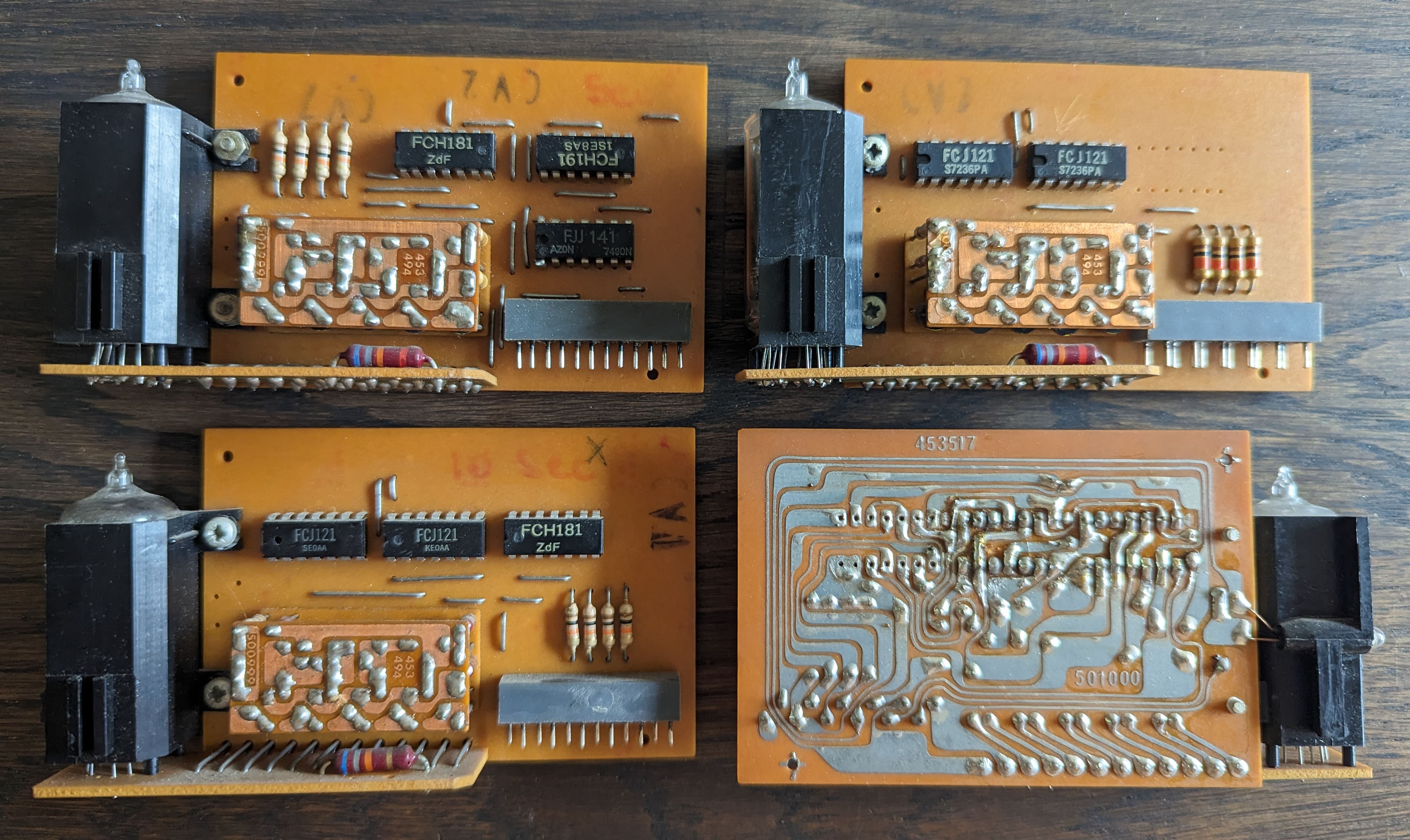
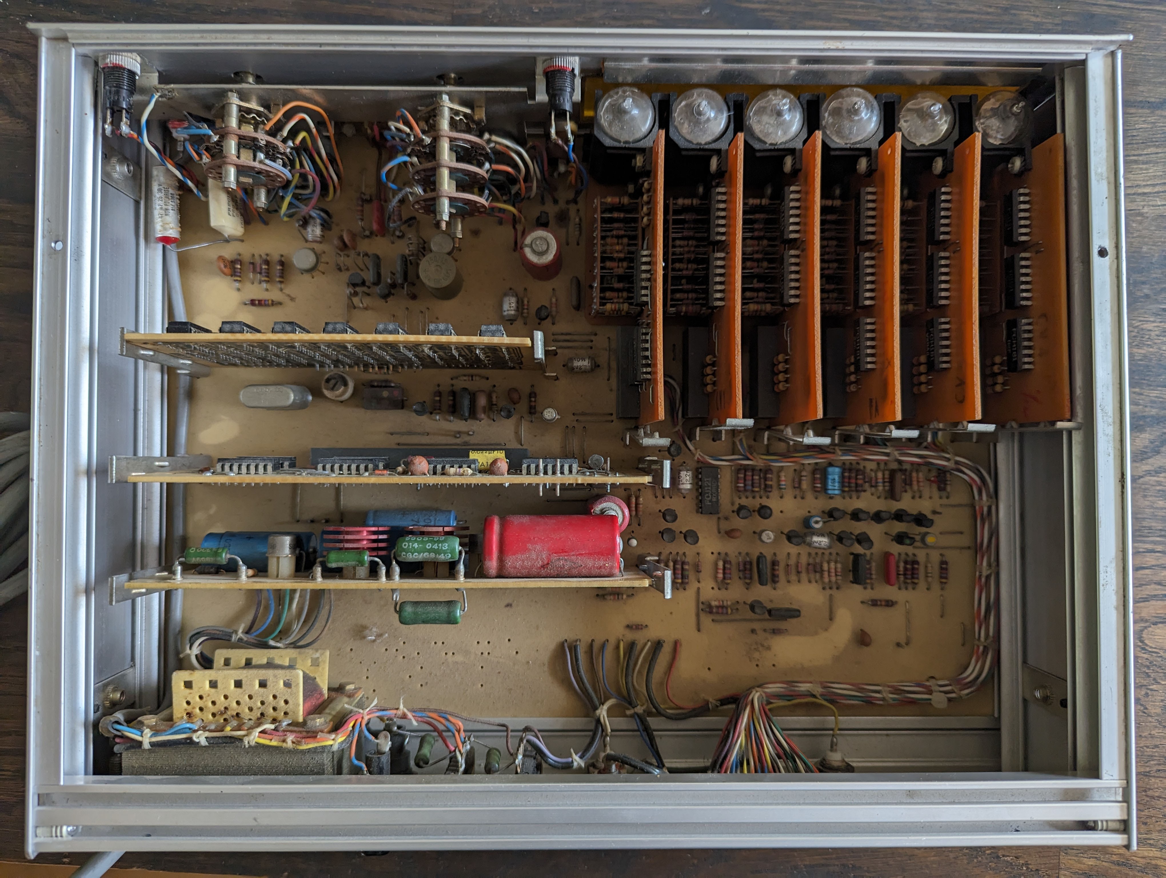
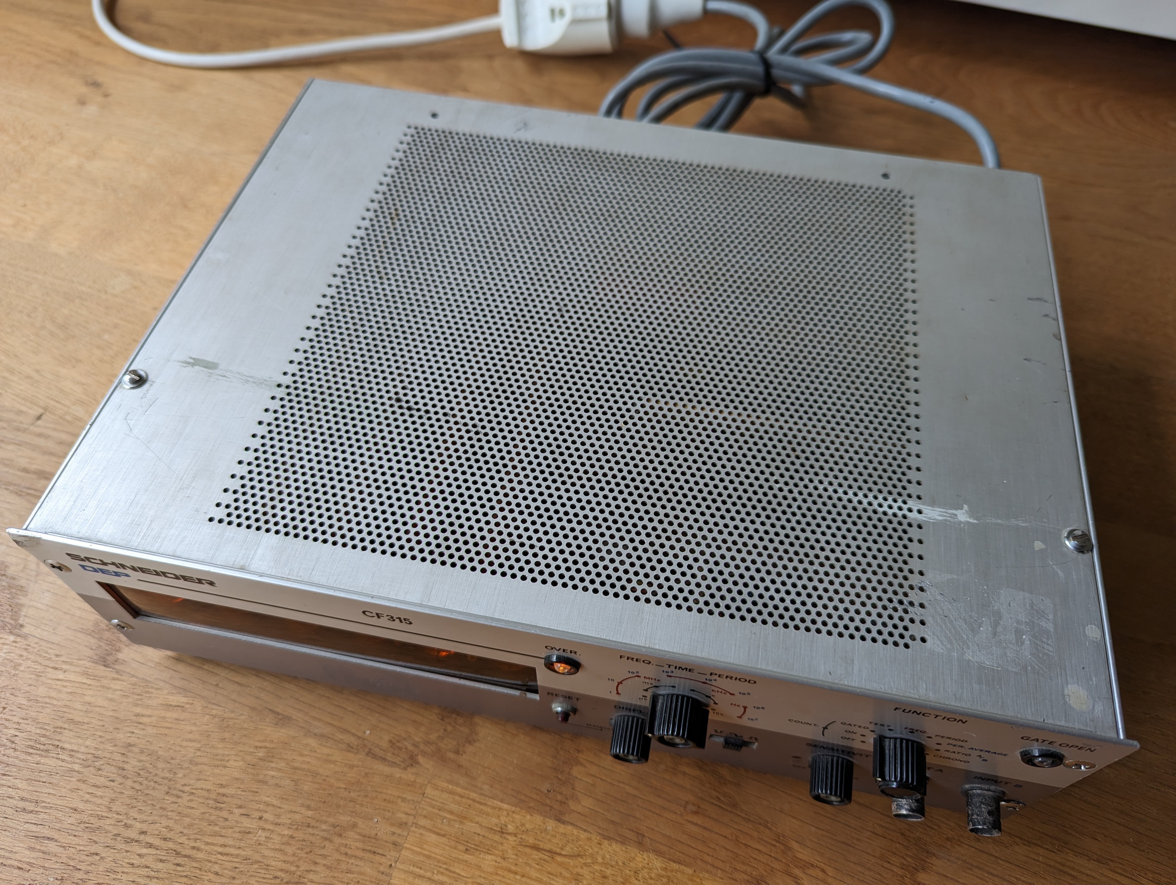
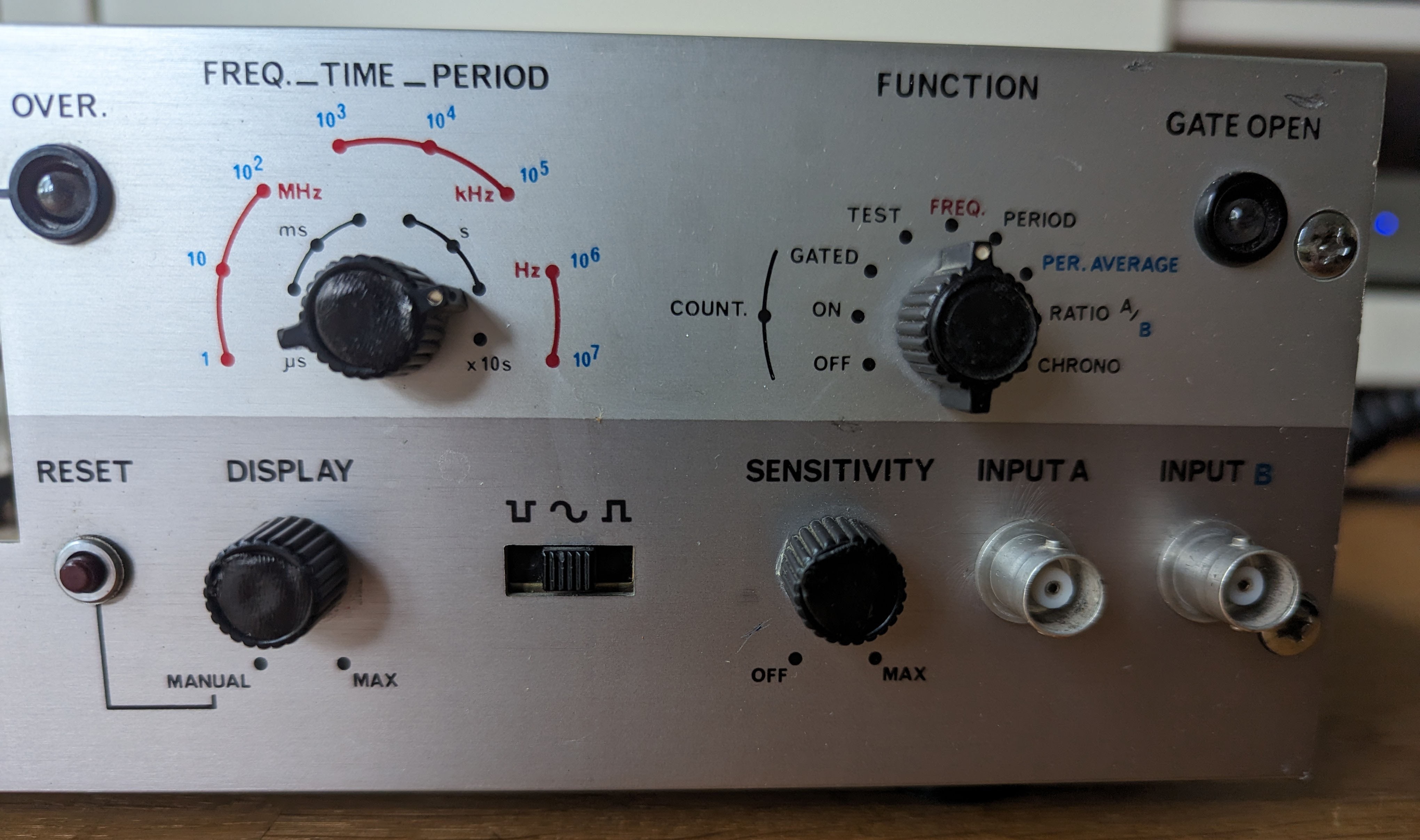
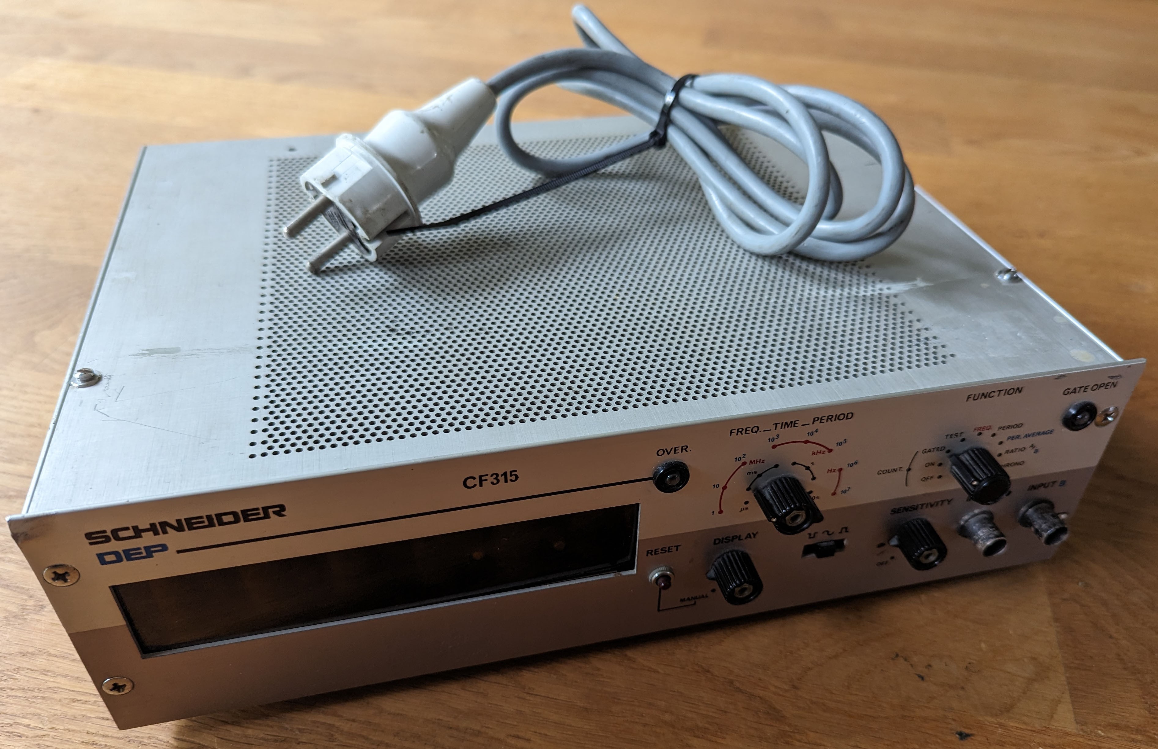
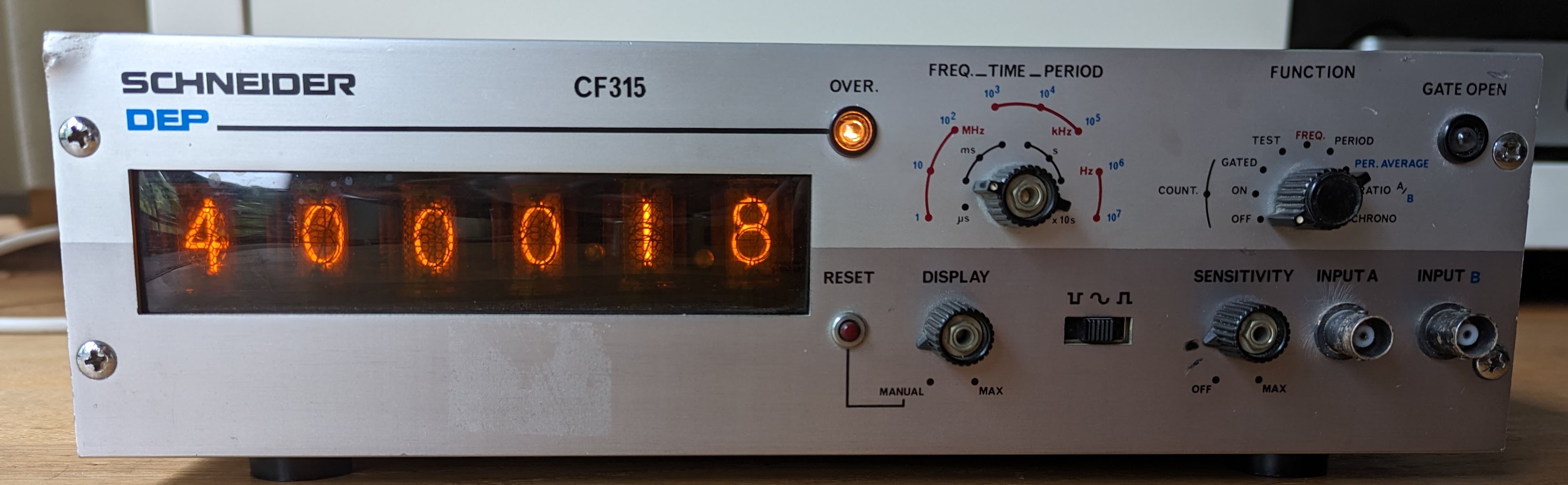
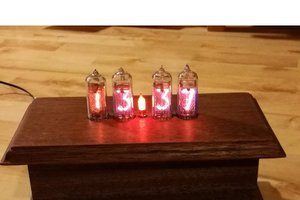
I bought a frequency counter, just because it had 6 nixie tubes. I am turning it into a clock. Plenty of similar projects have been done.
0%
0%
Frequency counter becomes Nixie clock
Turning an old device with Nixie tubes into a clock
Become a Hackaday.io member
Already have an account? Log in.
Just one more thing
To make the experience fit your profile, pick a username and tell us what interests you.
Pick an awesome username
hackaday.io/
Your profile's URL: hackaday.io/username. Max 25 alphanumeric characters.
Pick a few interests
Projects that share your interests
People that share your interests

 Spencer
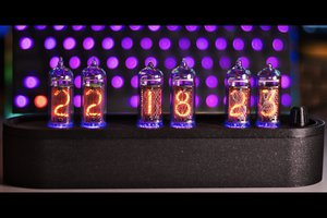
 Tobias
 Johan Winer
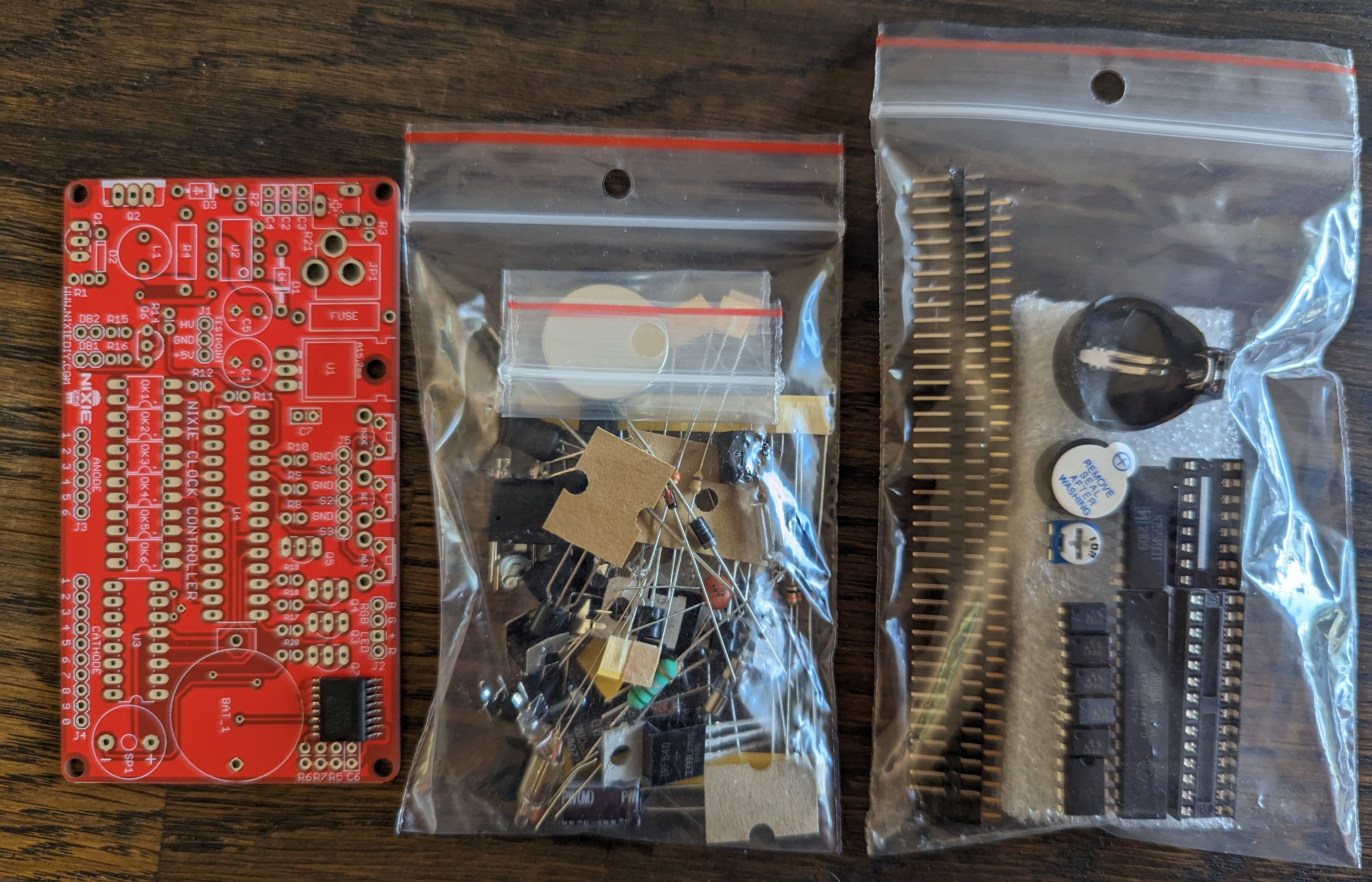
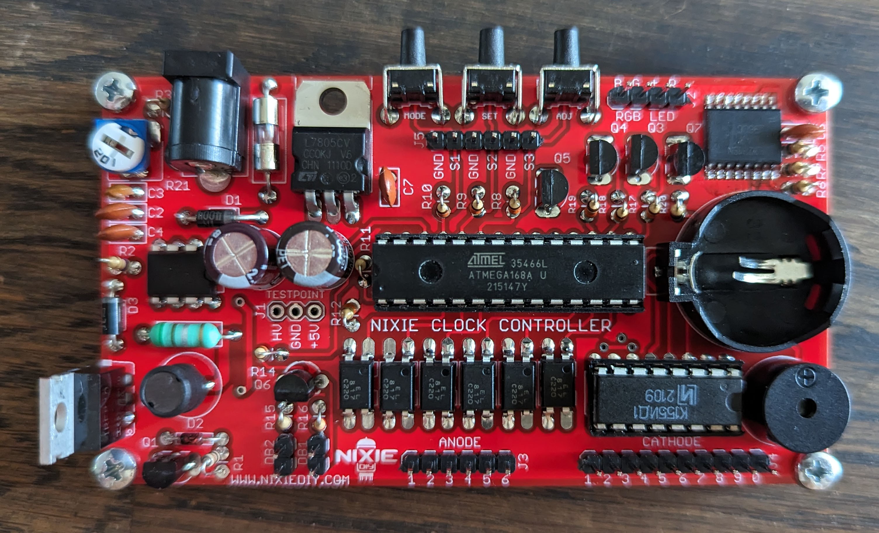
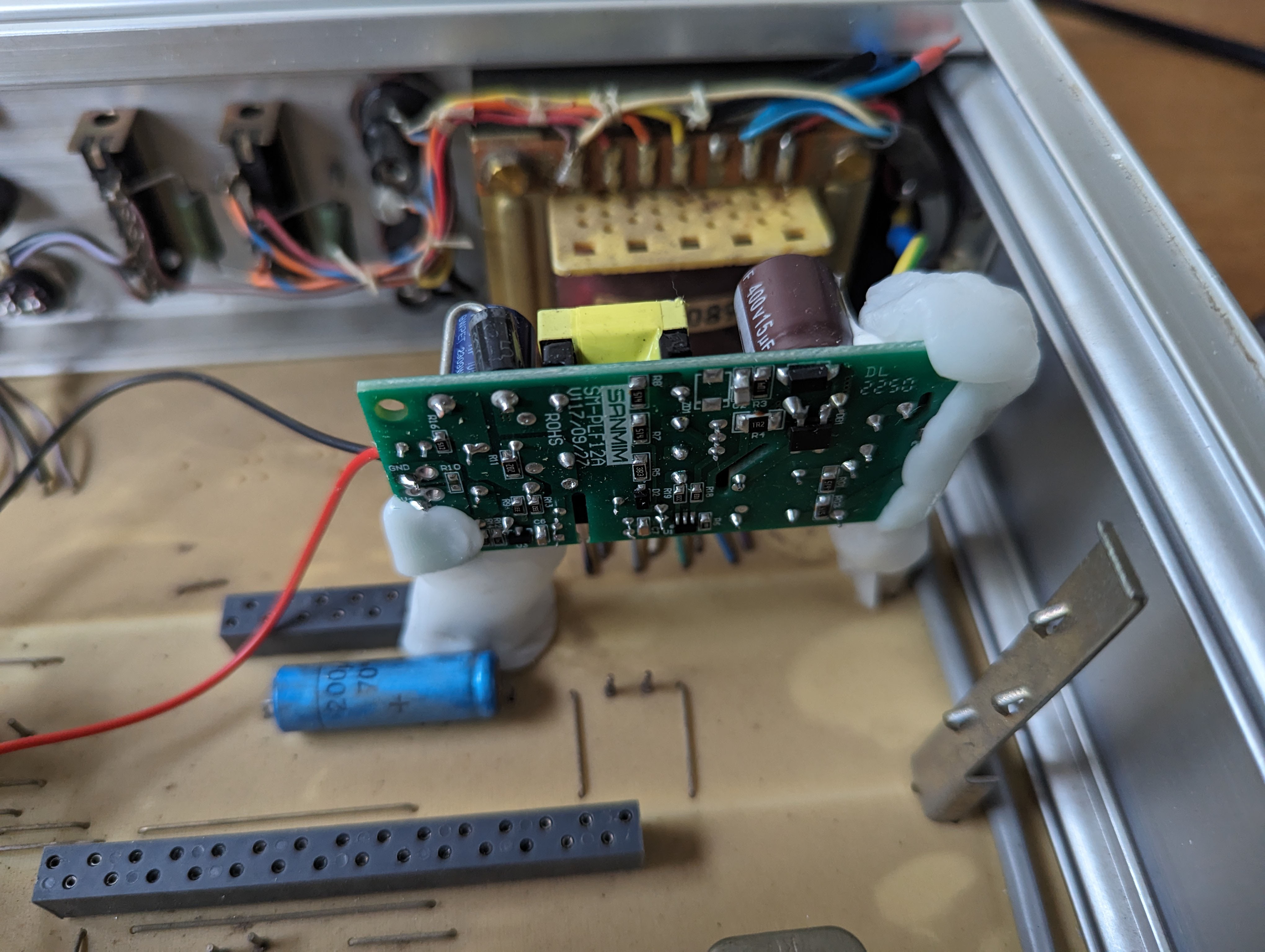
I like your approach where some of the old circuitry is saved. This project is less interesting, as I am basically just building the nixie kit and using the old enclosure. But I like to share it nonetheless.