 Walter
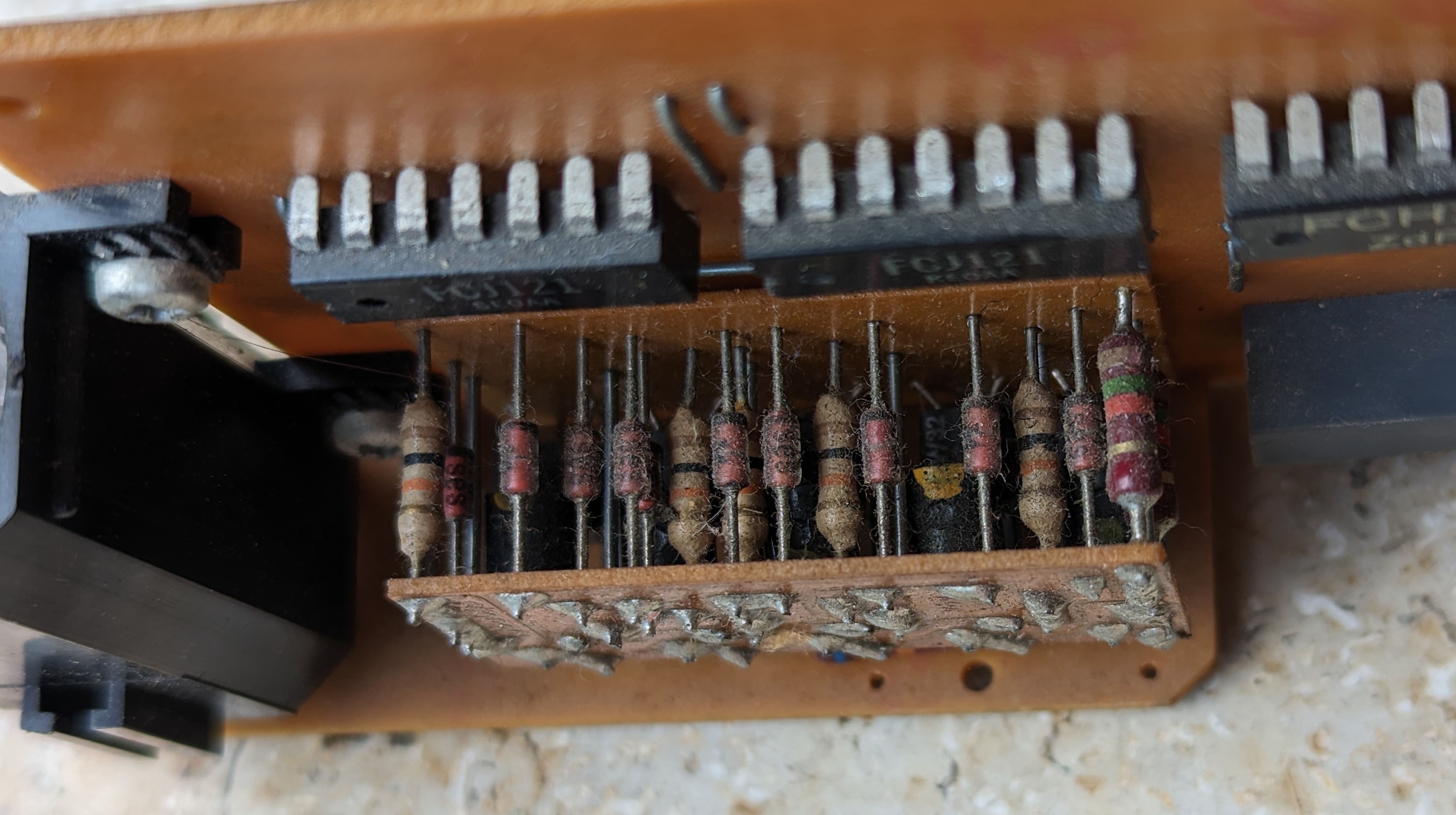
The comment on the last blog posting was that the "block" of components on the nixie boards could be the decoder. I took a picture of it, also showing the buildup of many years of dust. Indeed, we see resistors, diodes and transistors there, neatly packed together.
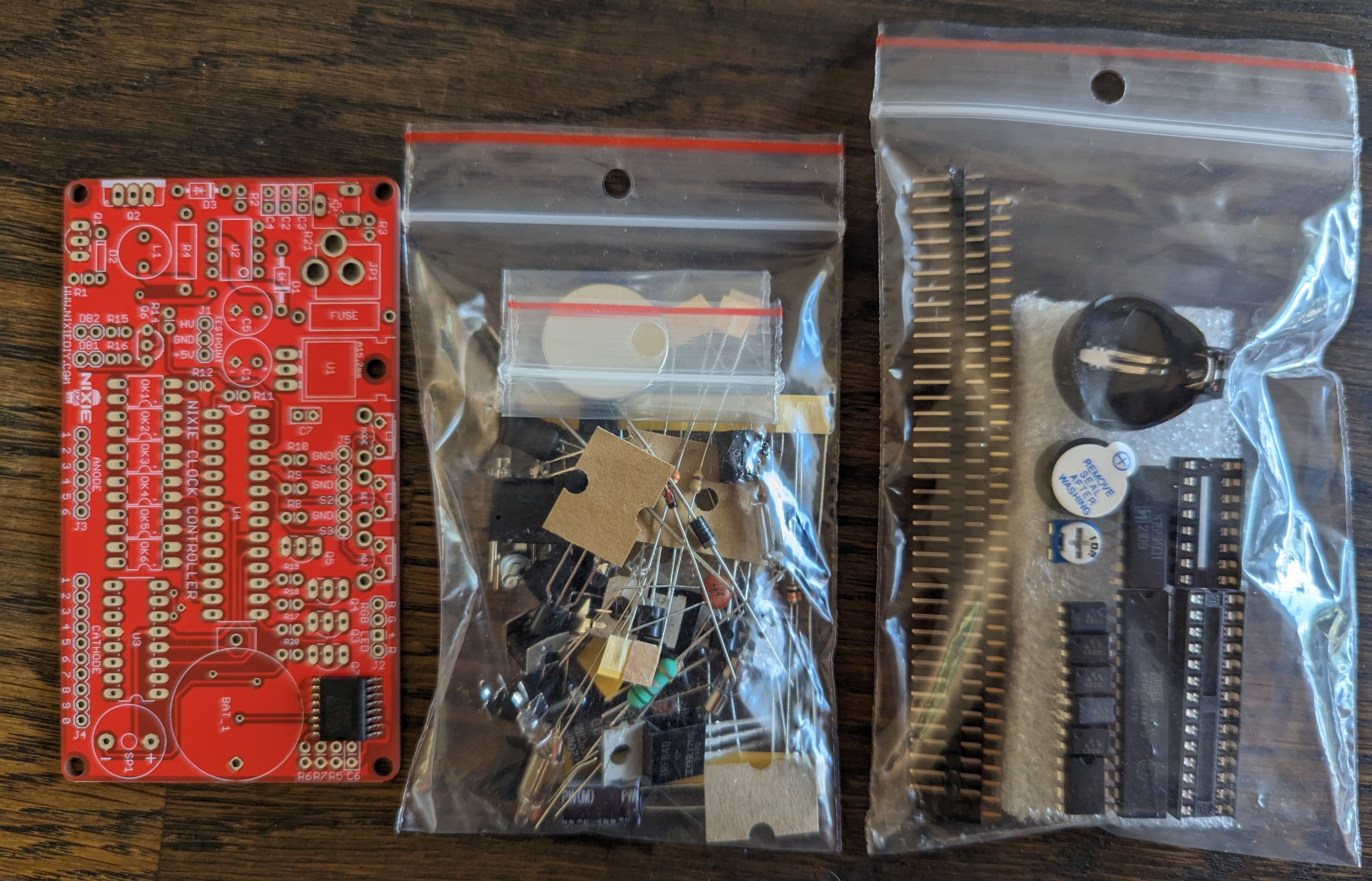
Today, the nixie kit arrived from http://nixiediy.com/. It came with a very nice manual, that reminded me a bit of the Gigatron manual I wrote.
I quickly soldered everything together and checked the voltages when hooked up to the buck converter. All was fine.
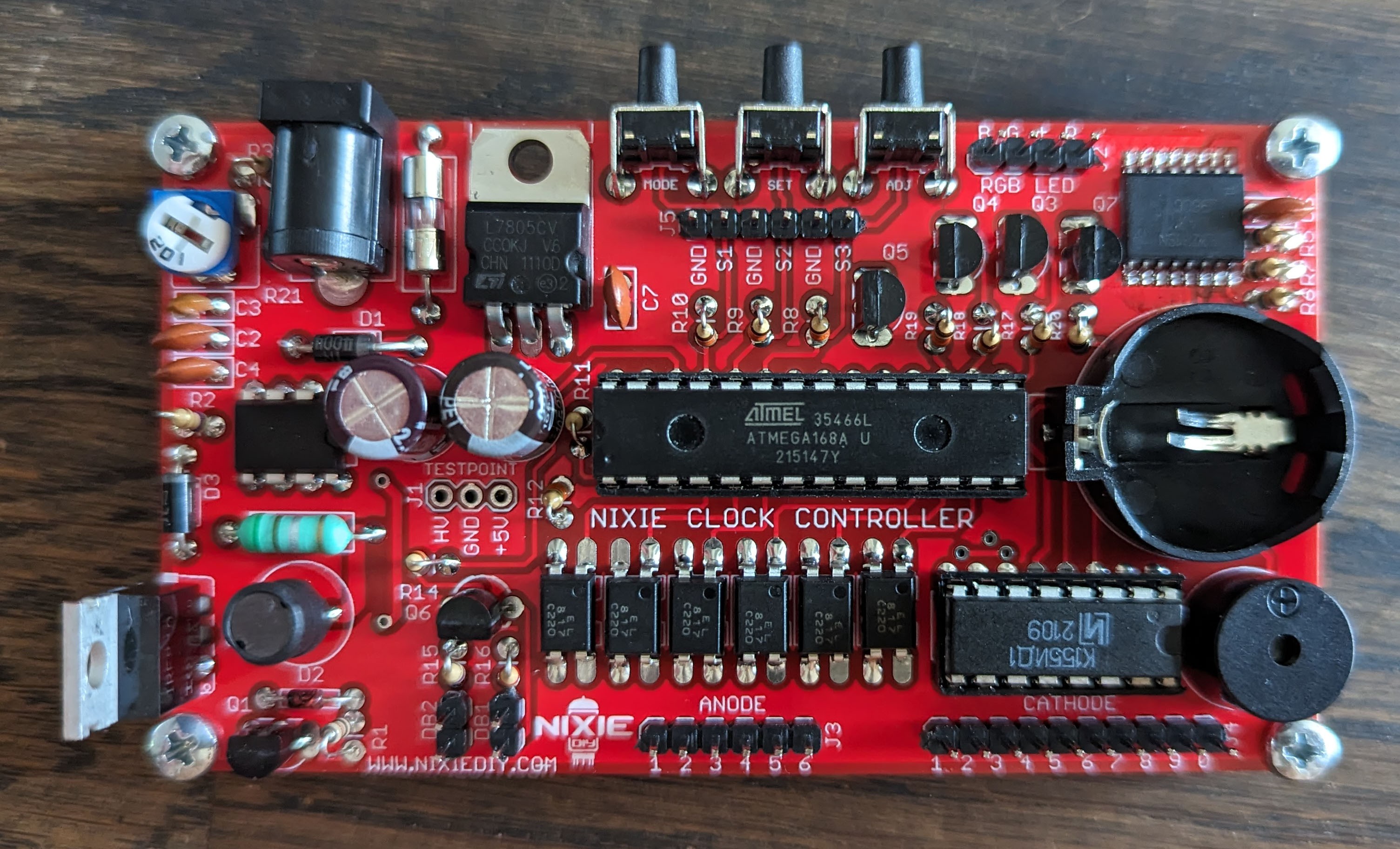
I'll insert the battery when it's fully hooked up. I am waiting for some wires to arrive to connect the tubes. But I can already start with putting this PCB in the enclosure, putting in the buttons and connecting the lights on the front panel.
Discussions
Become a Hackaday.io Member
Create an account to leave a comment. Already have an account? Log In.
Ah I see the clock board is driving the nixies multiplexed. That will reduce the number of wires to the nixies.
Are you sure? yes | no