 Int-Mosfet
Going to make 1 project log. So this was just something I made one Saturday when I should've been studying for finals (needed to work on something else) and really wanted to make an entry for the Hackaday 1K Challenge. I have some space to add on a few things like an IR receiver and a simple serial output but I knew I didn't have a chance against other competitors and had another project I wanted to finish. Also didn't build up perf-board for this as I want to use the dev board for something else.
Anyway, I'll just document the pinout here in text instead of a picture. The cap touch module has 3 lines on the back: G, V, S. As you could probably guess, G is Ground, V is volts or +3.3V, and S is signal line. Very easy to hook up. So for that module to the PIC16F18855 dev board, pinout is as follows:
G => GND
V => 3.3V
S => RA6
Next is the pinout for the Keyes relay module. Very easy again, there's a signal line (S), a 5V line and a GND line. Pinout is as follows from PIC16F18855 dev board to Keyes relay module:
RA7 => S
5V => +
GND => -
That's it, I configured the outputs in pin_manager.c on the github repository, and I'm looking for an active low signal from the cap touch IC. I turn on 4 LED's (so you could activate 4 other things besides LED's) and the relay module when cap touch module is touched.
To verify the file size, I looked at the .hex file which is what is flashed to the PIC, on the github too in the "dist/free/production" tab. It's 444 bytes. That's about all there is to say about this project.

 Sai Yamanoor
 Daniel Eisterhold
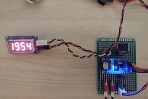
 Ken Yap
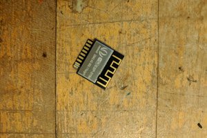
 Sophi Kravitz