 Anton Khrustalev
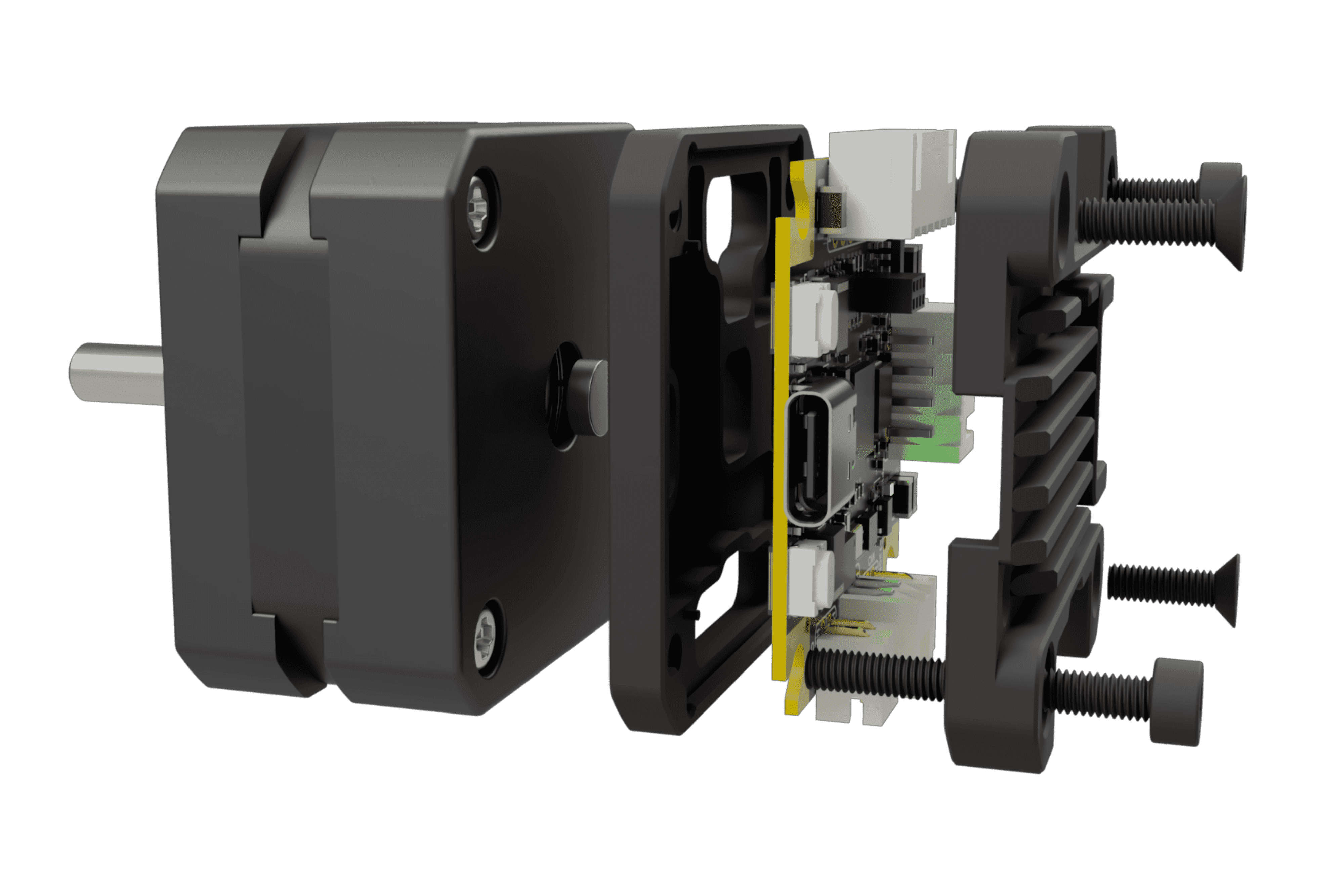
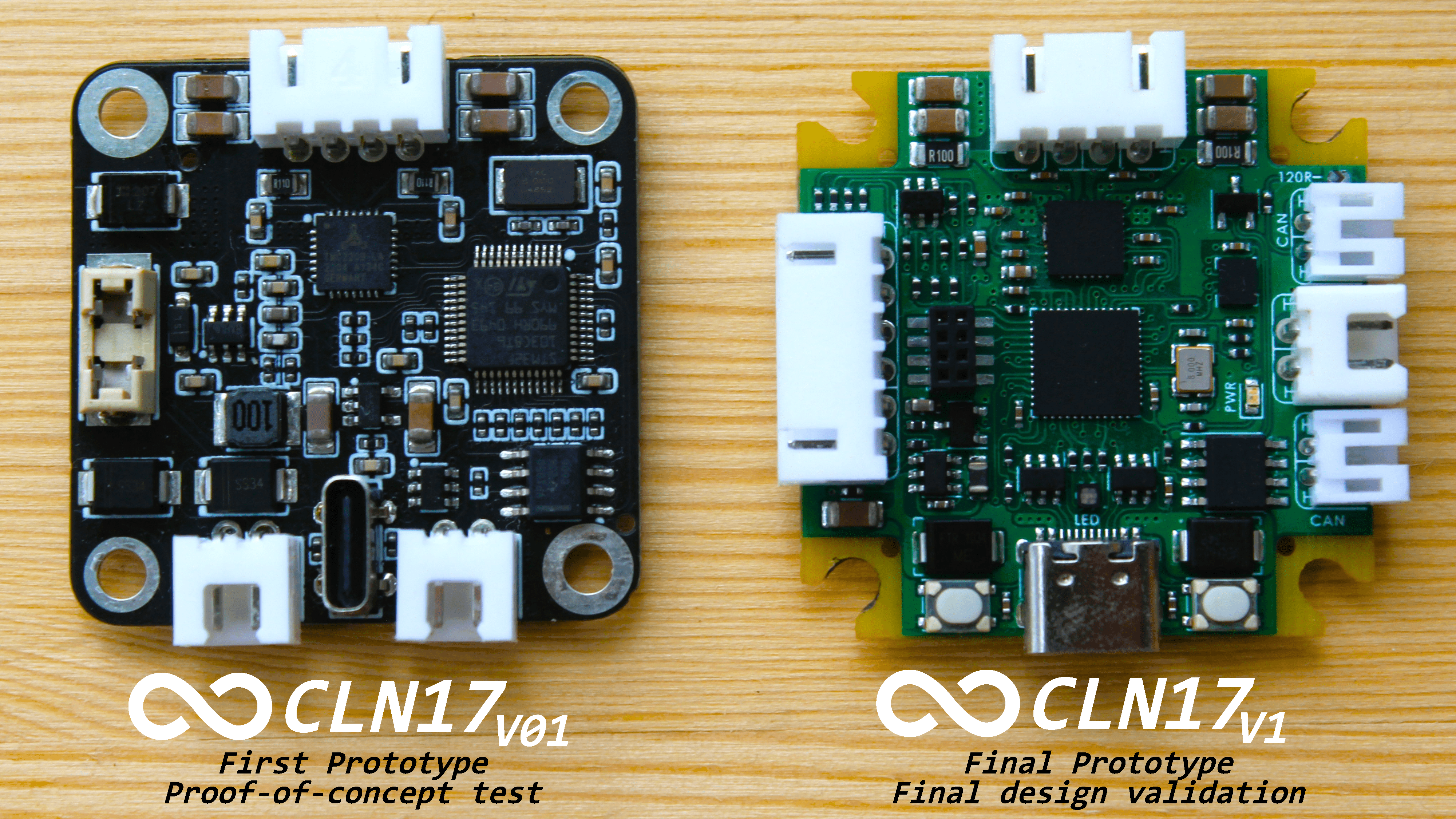
Assemly preview
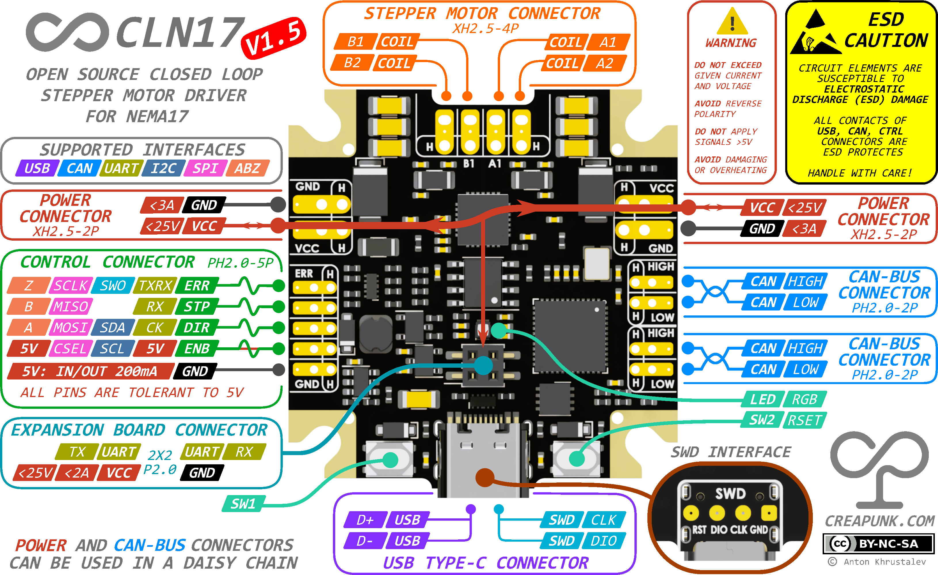
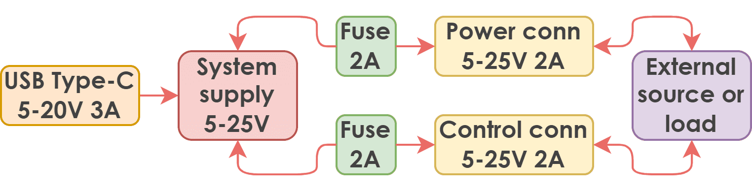
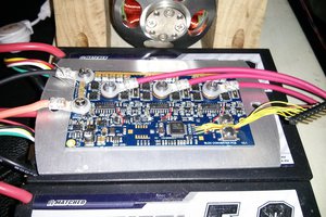
Board Diagram
Key Features | All Features
- 🕹️ Closed-Loop Control: Enables precise motion in challenging conditions.
- 💪 Adaptive Torque Control: Optimizes energy efficiency, reduces stress, and extends motor lifespan.
- 🧩 Reliable Operation and Enhanced Safety: Ensures reliable operation and protects users from potential harm.
- 🛡️ Modular Concept: Provides flexibility and cost-effectiveness through various configurations and expansion boards.
Key Specs | All Specs
- 🔌 Wide Input Voltage Range: 8-48VDC with reverse polarity and surge protection
- ⚡️ Powerful Motor Control: 1.75A RMS current per phase with up to 2A peak
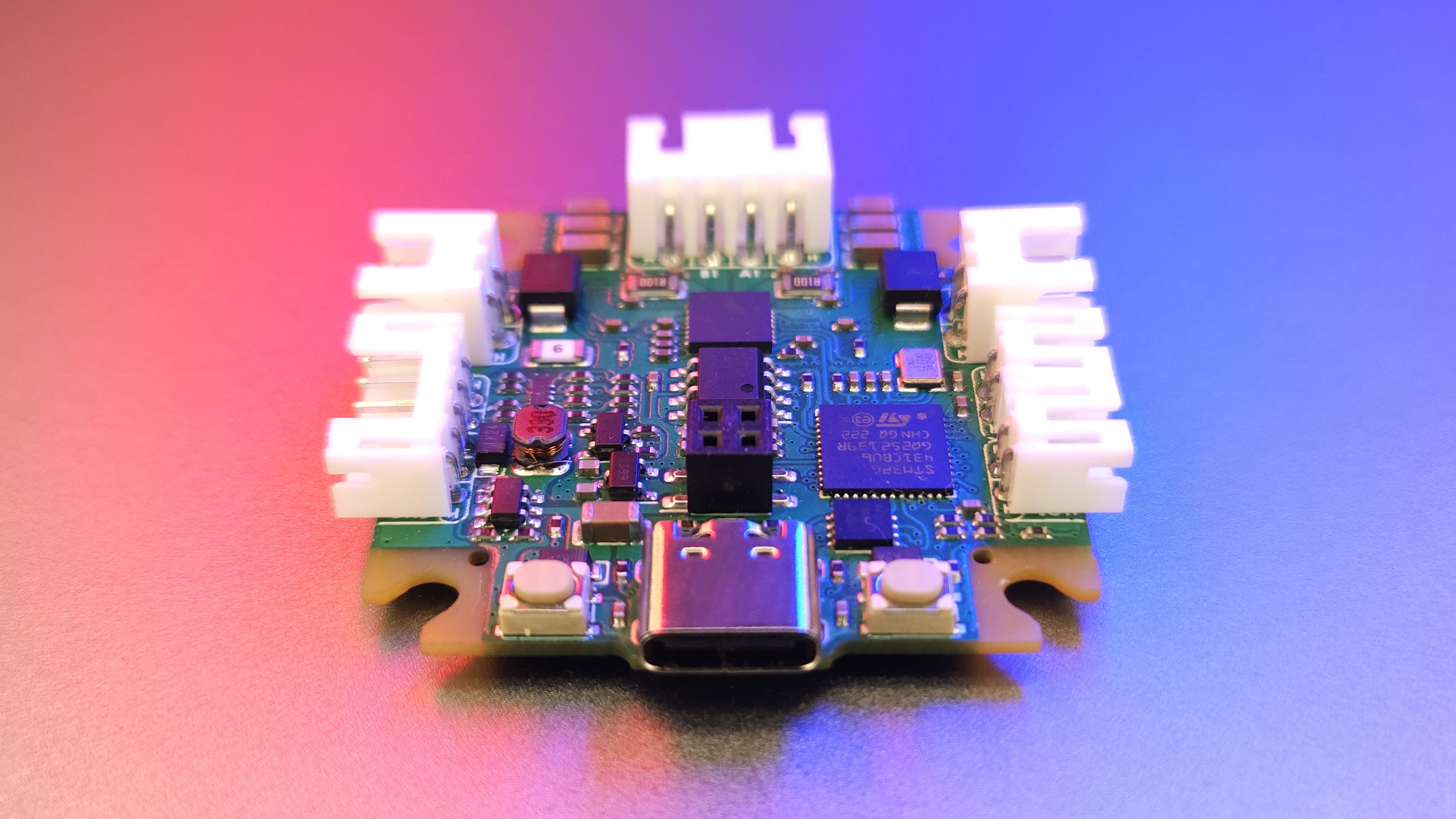
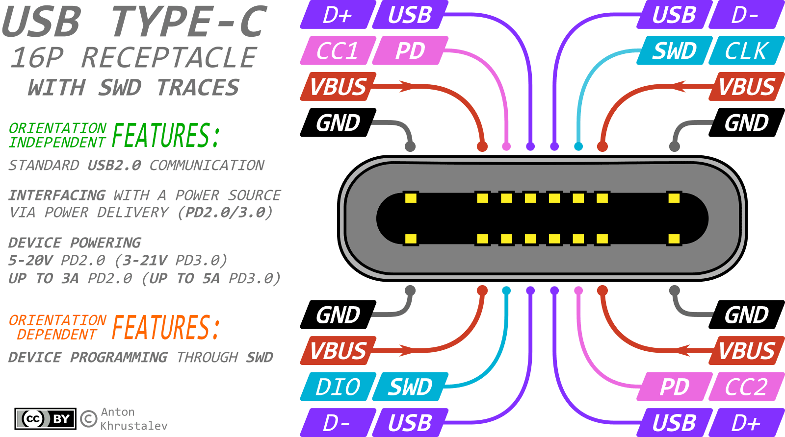
- 🚀 High-Performance MCU: STM32G431CB Arm Cortex-M4 running at 170MHz with Classic EN/DIR/STEP interface, CAN-Bus, I2C, UART and USB Type-C
- 🔒 Compact and Durable Design: 38x38mm PCB, with optional aluminum housing for heat dissipation and mechanical protection and minimal height of 7.5mm (10mm with connectors)
Applications | In-depth
- 🎓 Learning Platforms
- 🛠️ CNC Machines & 3D printers
- 🤖 Robotics & Automation Systems
- 🤝 Collaborative Robots
- 🔭 Camera & Telescope Stabilization Systems
- 🔬 Laboratory Equipment
- 🏭 Industrial Motion Control Systems
- 📳 Haptics & Force Feedback Systems
What is the project's status?
There are numerous updates planned for the documentation, including the publication of articles on related topics. Alsowill be provided insights into development process, announce new versions, introduce new features, and much more. Visit GitHub page for details!
Design Overview
To fully grasp the design intricacies of the CLN17 project, it is recommended to familiarize yourself with its foundational principles, as they provide the conceptual basis for CLN17. Also see the CC BY-NC-SA 4.0 license.


 Mark Atherton
 Chu Tien Thinh (obitvn)
 Jarrod
Hey, great project! Where can I find the code it is not on gihtub.