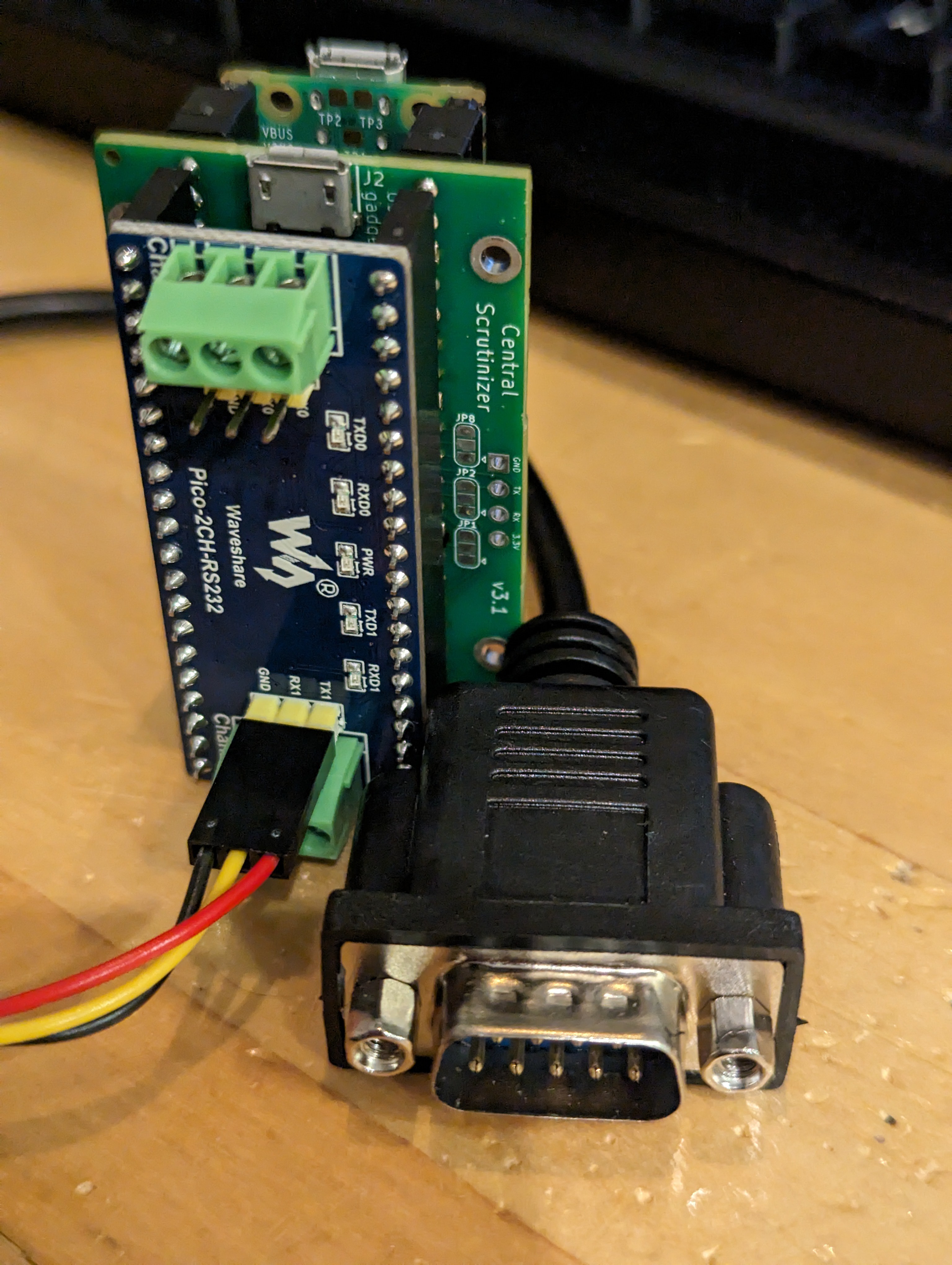
The Central Scrutinizer provides a low-level serial port over USB to operating system developers hacking on fruity hardware, which is useful when you cannot count on display/keyboard to be available (headless machine), or need to log information but can't use any local storage.
If you're using MacOS on your Apple Silicon machine, you probably don't need the serial console aspect, but the reboot feature can prove useful if you crash the machine and need to remotely reset it.
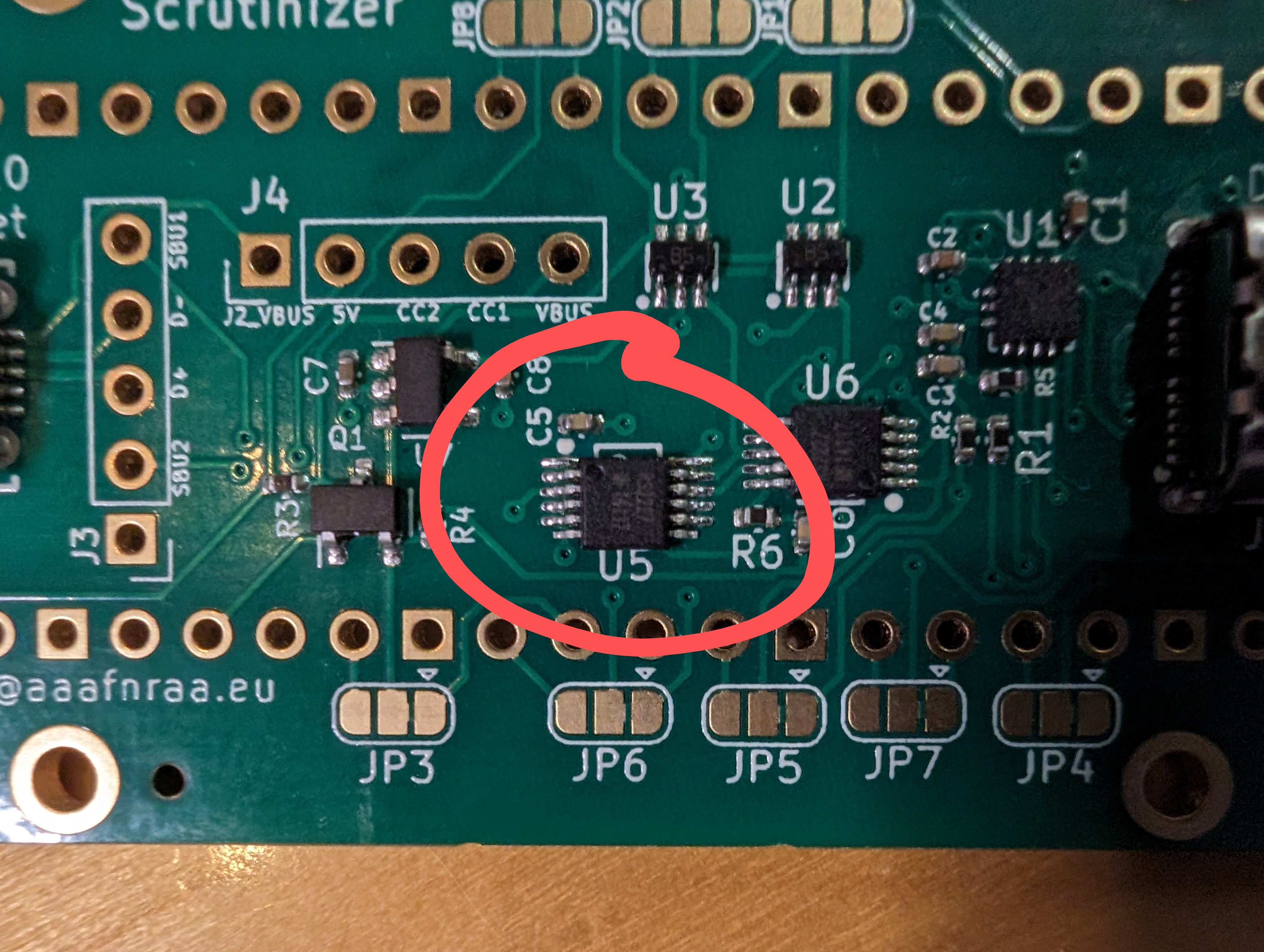
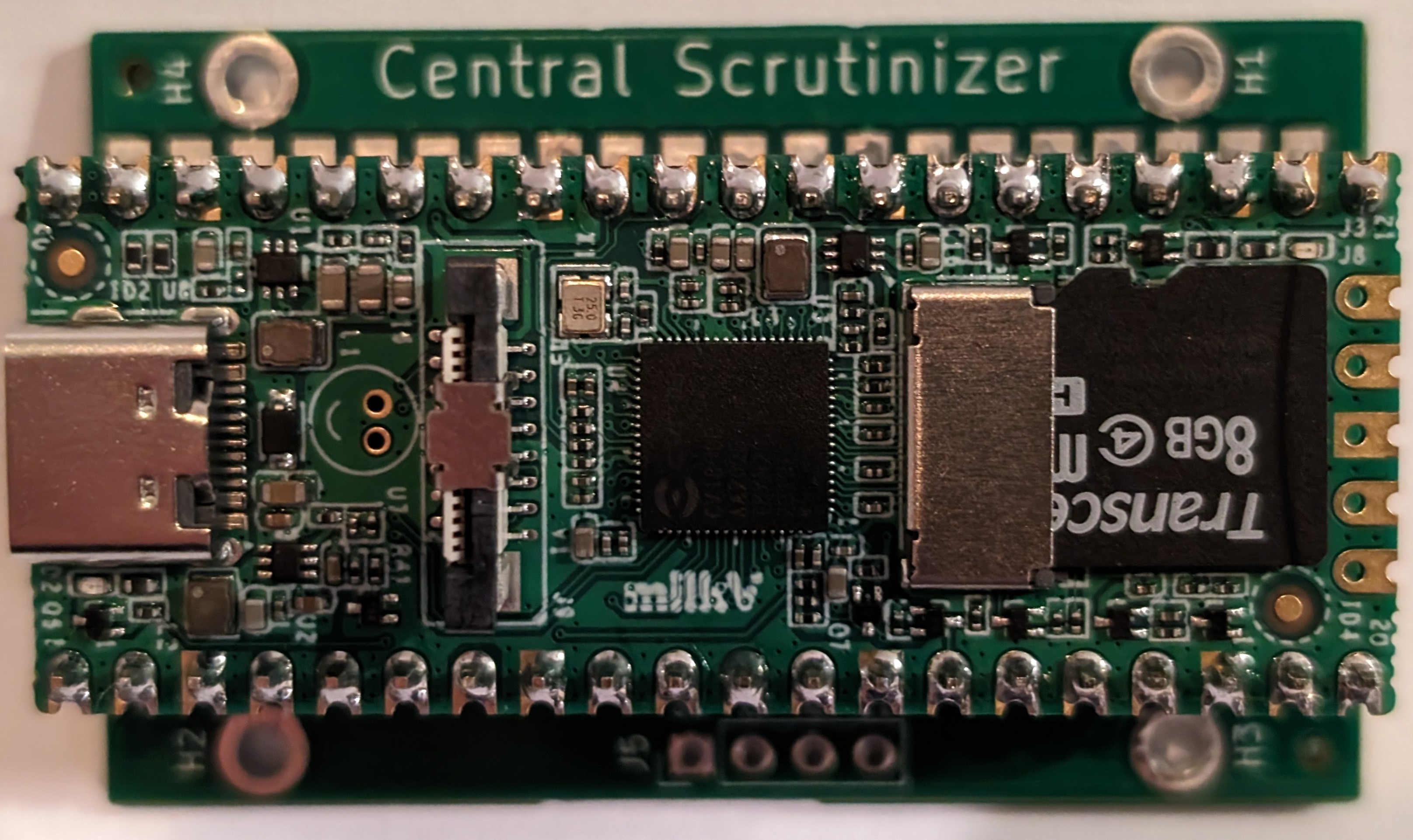
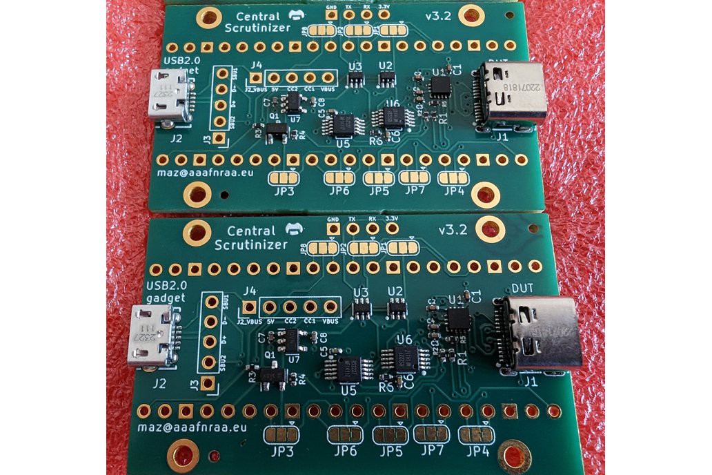
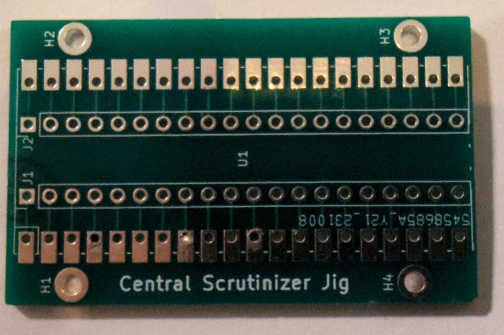
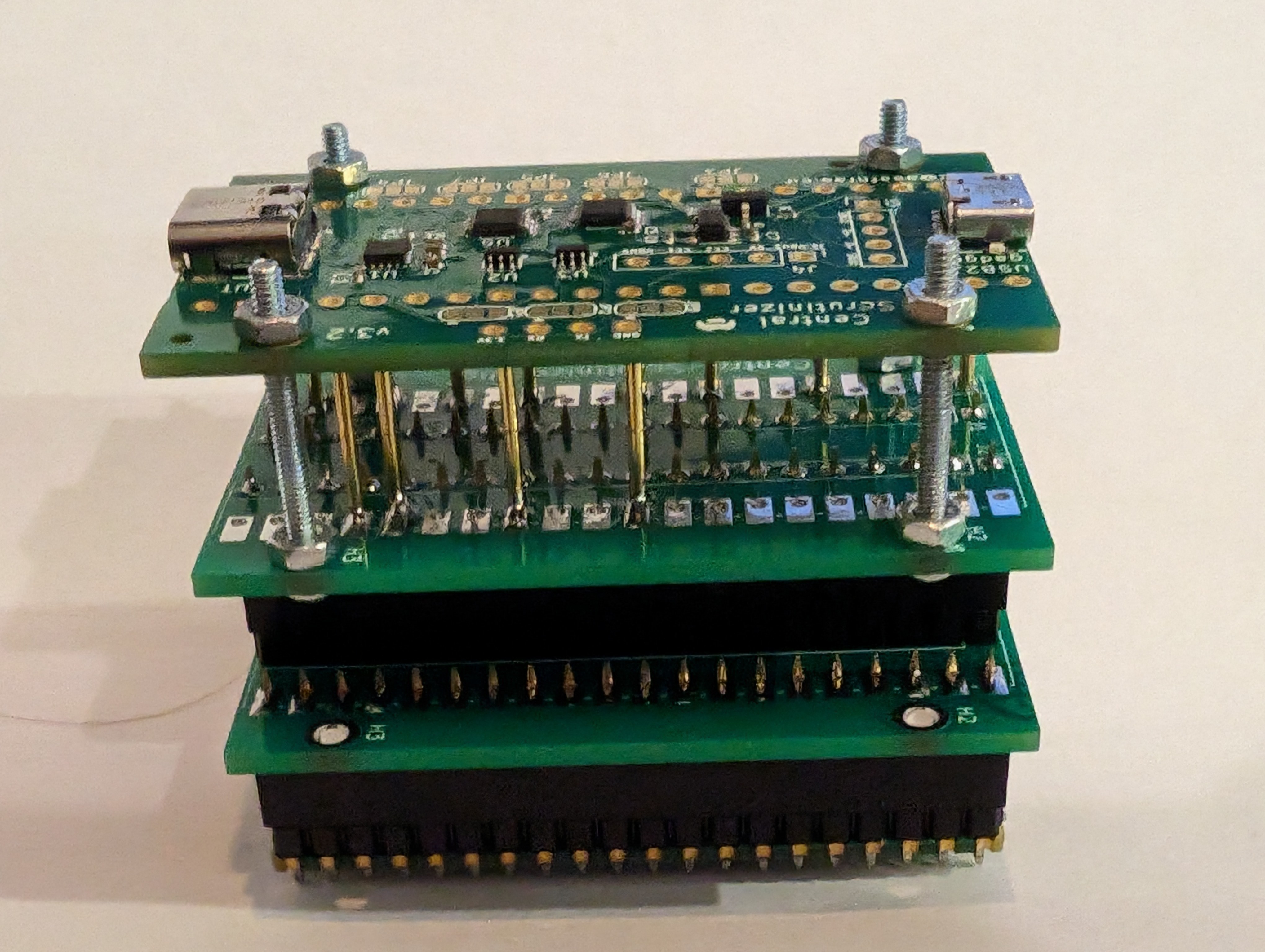
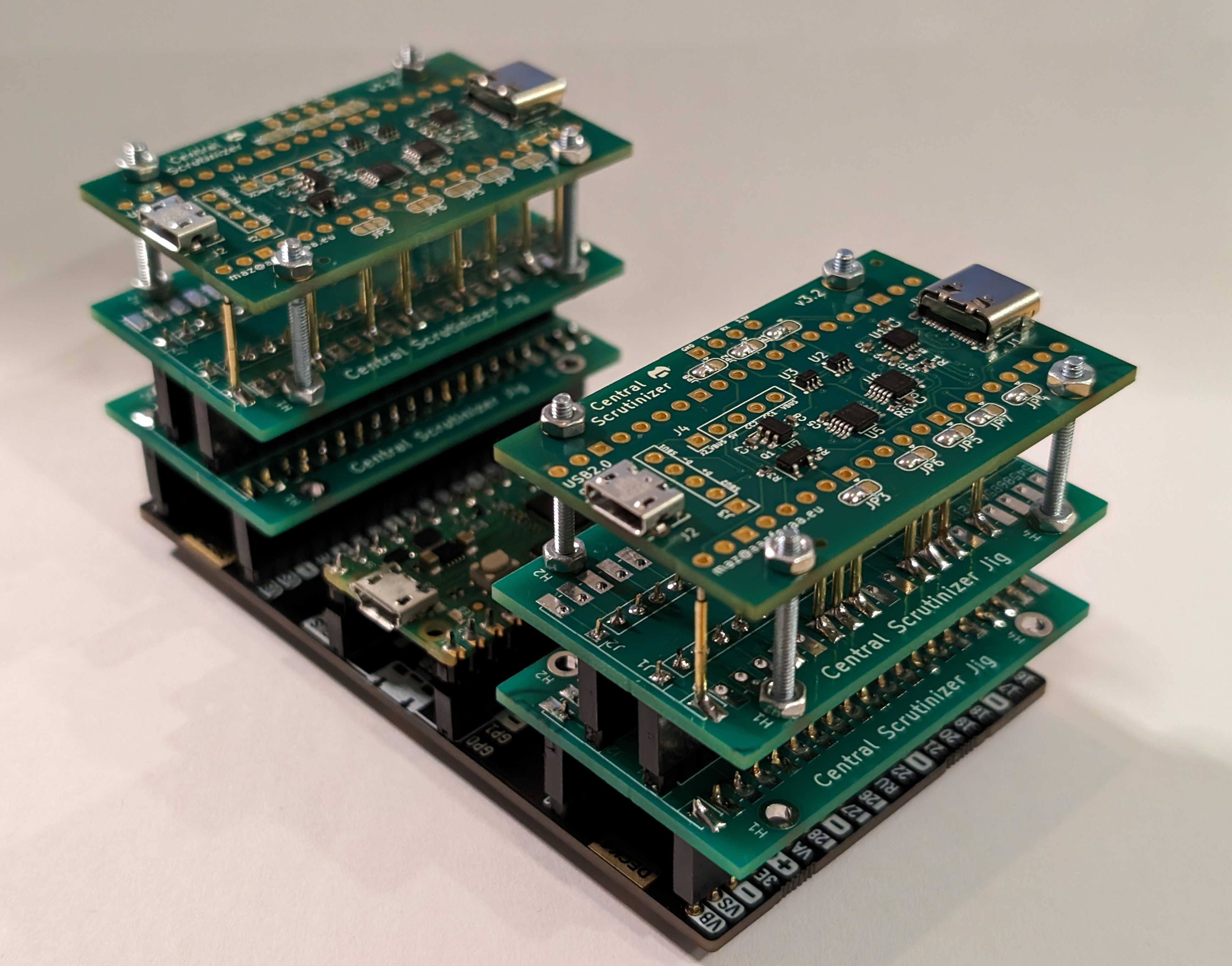
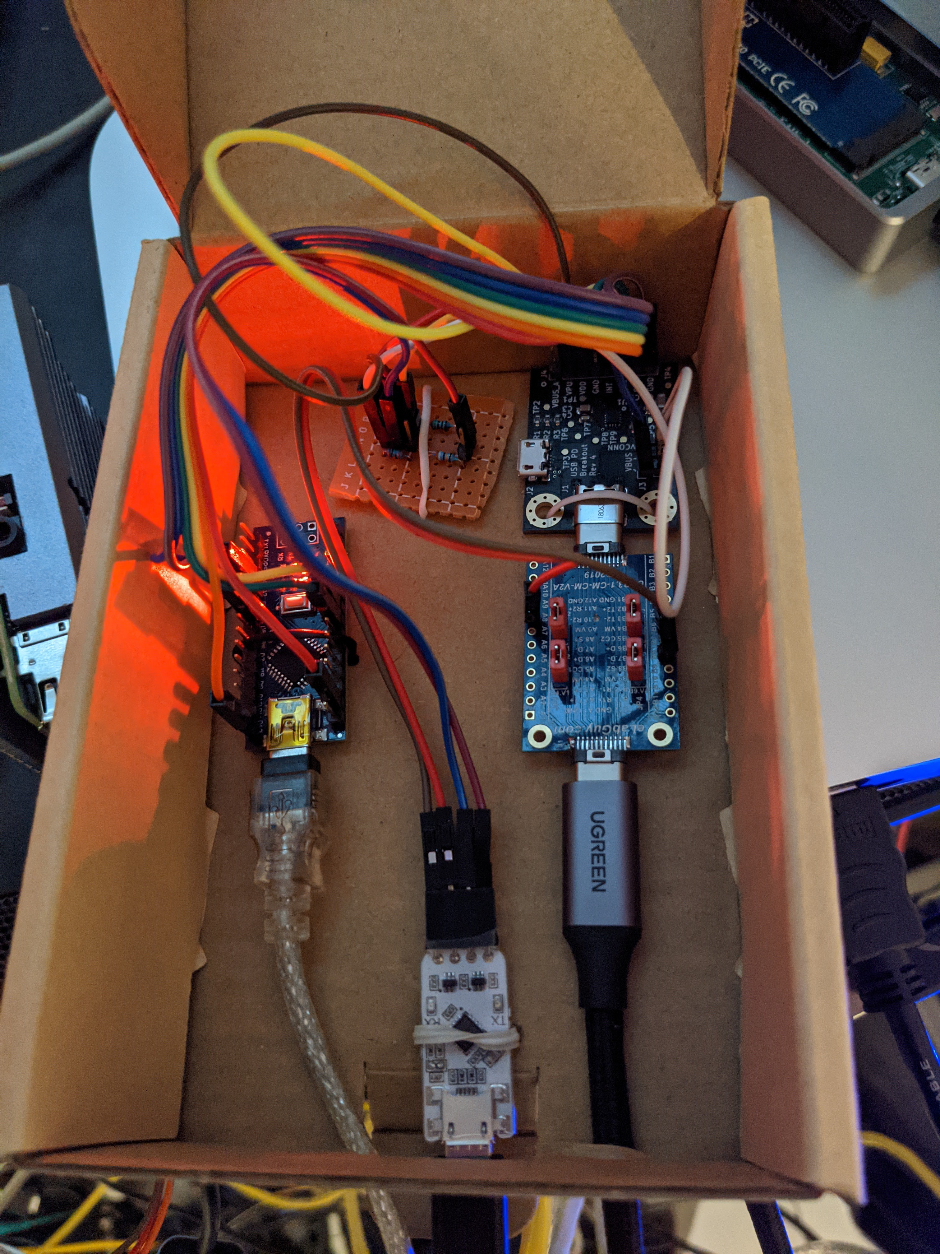
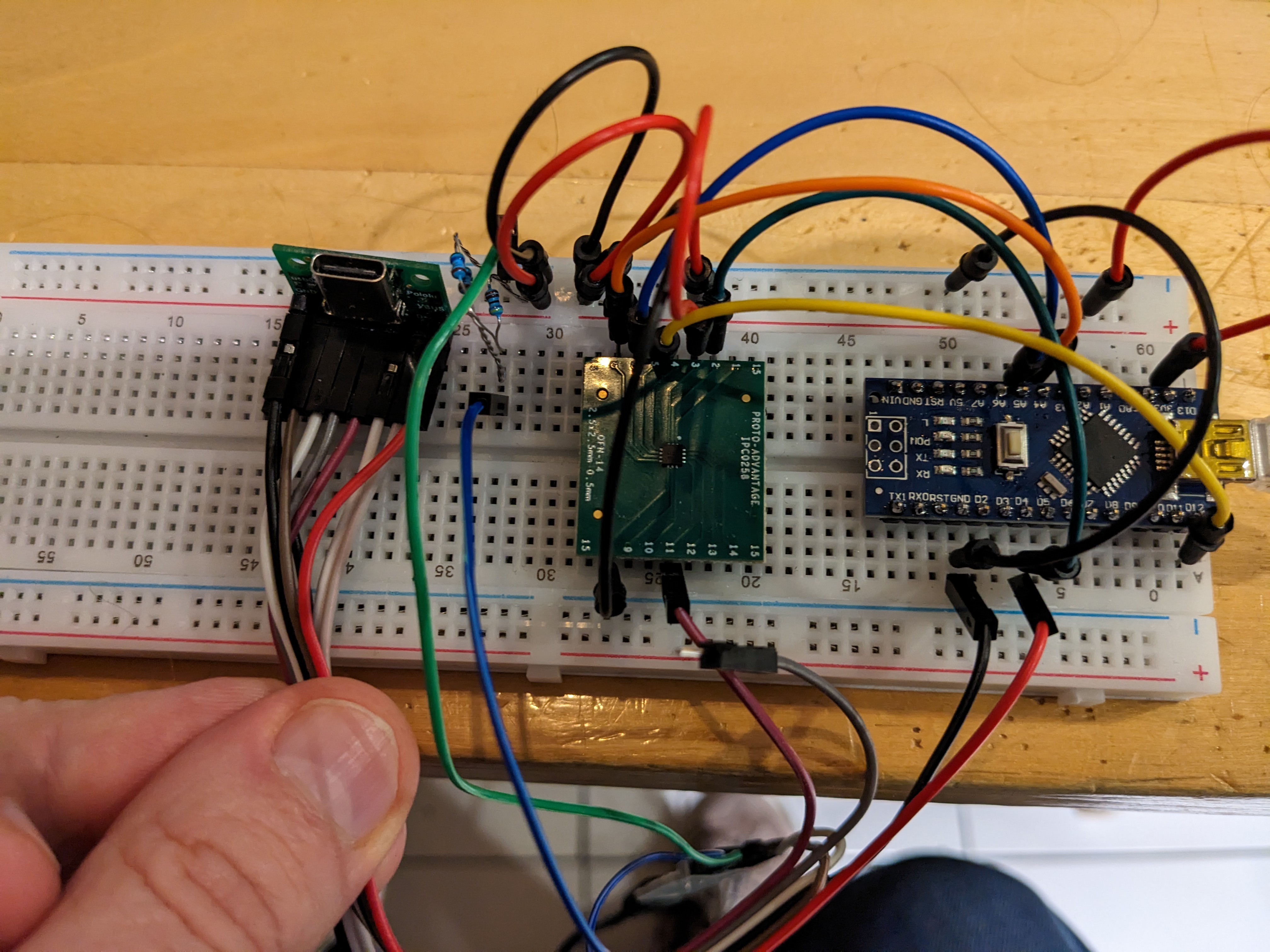
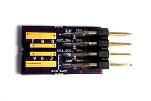
It is build with a small PCB of my own design, coupled to a RaspberryPi Pico that runs the control firmware.
Plenty of extra information in both git repositories (see the left sidebar for links to the KiCad files as well as the firmware source code)!
Want to see an M1 booting Linux over the serial port? Here's one!
Being an open-source project, I'm always happy to take patches and suggestions.
 ajlitt
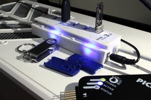
 Jarrett
 Daniel Grießhaber
 lpaseen