 Anton Khrustalev
This page will be updated soon
New media, reference designs, project source files, and firmware instructions will be available soon!
An enhanced version will be developed if there's significant interest in the idea. Subscribe to the community server to stay updated on project news!
Usage configurations
1. Classic Programmer
Usage similar to the classic ST-Link
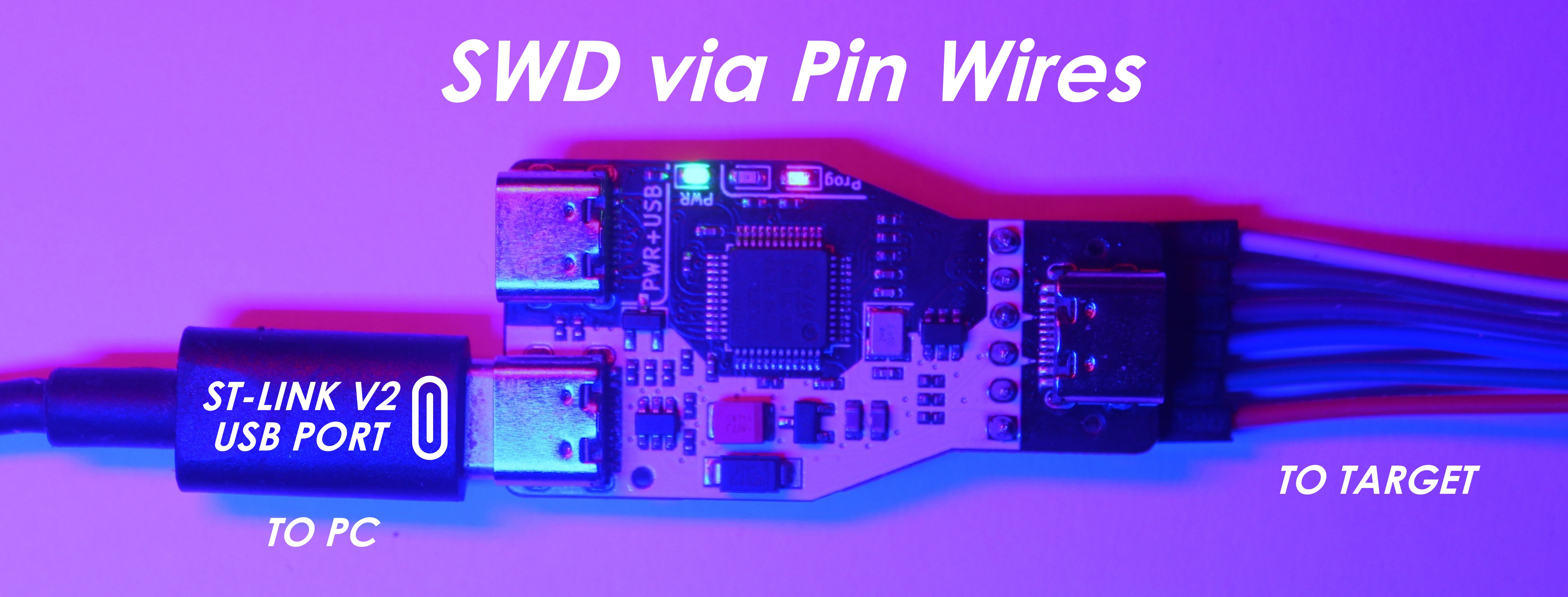
Connection to the computer:
- Programmer connector via Type-C that supports USB2.0.
Connection to the target:
- SWD interface pin ribbon.
2. Classic Programmer with USB2.0 and PowerDelivery Line Transit
For simultaneous firmware updates and debugging
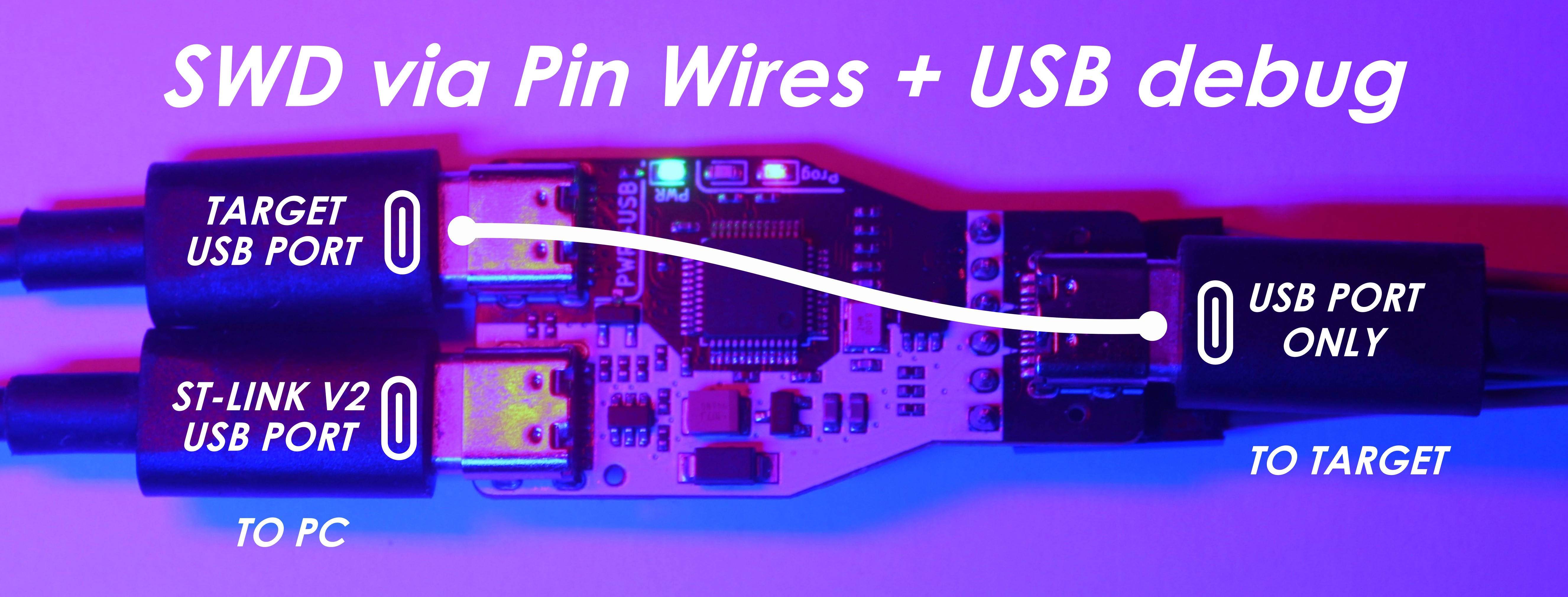
Connection to the computer:
- Programmer connector via Type-C that supports USB2.0.
- Target connector via Type-C that supports USB2.0 and PowerDelivery (if required by the target).
Connection to the target:
- SWD interface pin ribbon.
- Target connector via Type-C that supports USB2.0 and PowerDelivery (if required by the target).
3. Programmer over Type-C with USB2.0 and PowerDelivery Line Transit
For simultaneous firmware updates and debugging via single USB Type-C Cable
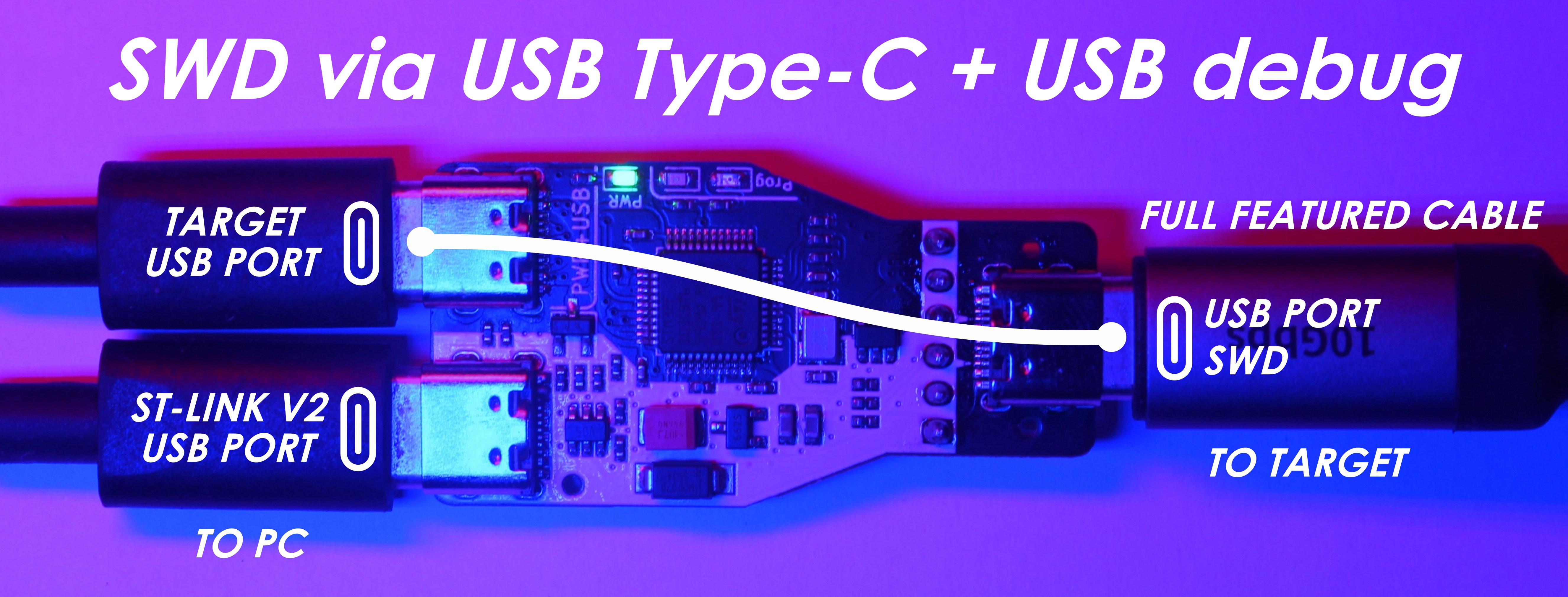
Connection to the computer:
- Programmer connector via Type-C that supports USB2.0.
- Target connector via Type-C that supports USB2.0 and PowerDelivery (if required by the target).
Connection to the target:
- Only the target connector via Type-C that supports USB3.0, PowerDelivery, and SideBand channel (Full Featured Cable).
Note1: a cable with SBU contacts is required. All cables supporting Alternate Mode, for instance, DisplayPort, have these lines.
Note2: SBU1 and SBU2 depend on orientation, thereforeit's crucial to orient the cable correctly.
Is it legal?

In terms of compatibility, the Type-C standard dictates that the impedance of inactive SBU lines should exceed 950kOhm. With CMOS-based communications (like UART and SWD), this specification is almost always met. Additionally, if a Type-C cable lacks USB3.0 support, it likely won't carry SBU signal lines, eliminating potential concerns. And given the resilience of UART and SWD protocols, coupled with their data integrity checks, inadvertent mishaps are unlikely.
Advantages:
- Single connector on the board, ensuring reliable contact.
- Eliminates the need for bulky programming pads, especially in micro-projects.
- Debugging flexibility with extended cables.
- Firmware updates without having to disassemble the device.
Drawbacks:
- Mandatory attention to Type-C orientation since signaling is orientation-specific.
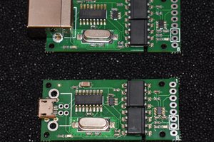
Schematic

 Łukasz Przeniosło
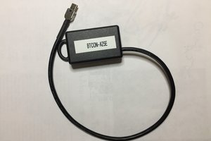
 ZeptoBit
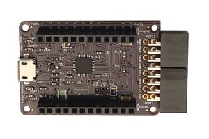
 Pattern Agents