 Supplyframe DesignLab
-
1Overview
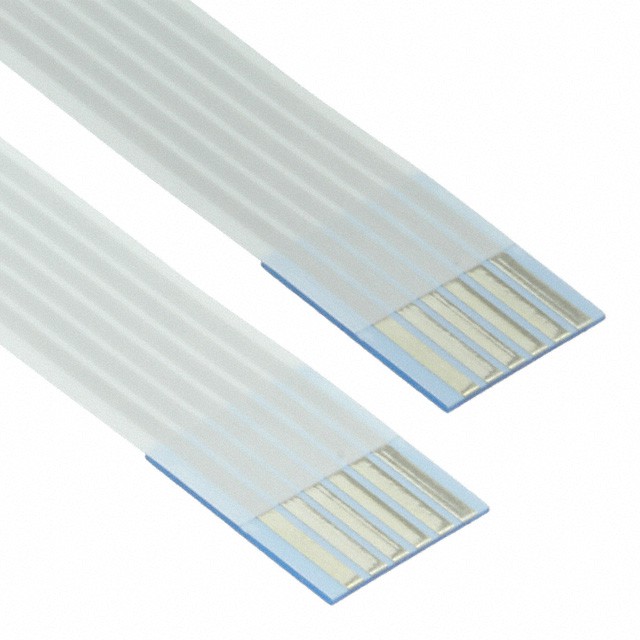
Controller and Lamp are connected with a ribbon cable (see Data Sheet). There are two available cables: 6 and 10". Depending on your design, you may choose one or the other.
![]()
The same goes for the four Lamp Board shapes. All have the same components. Please choose the one that better fits your design concept.
![]()
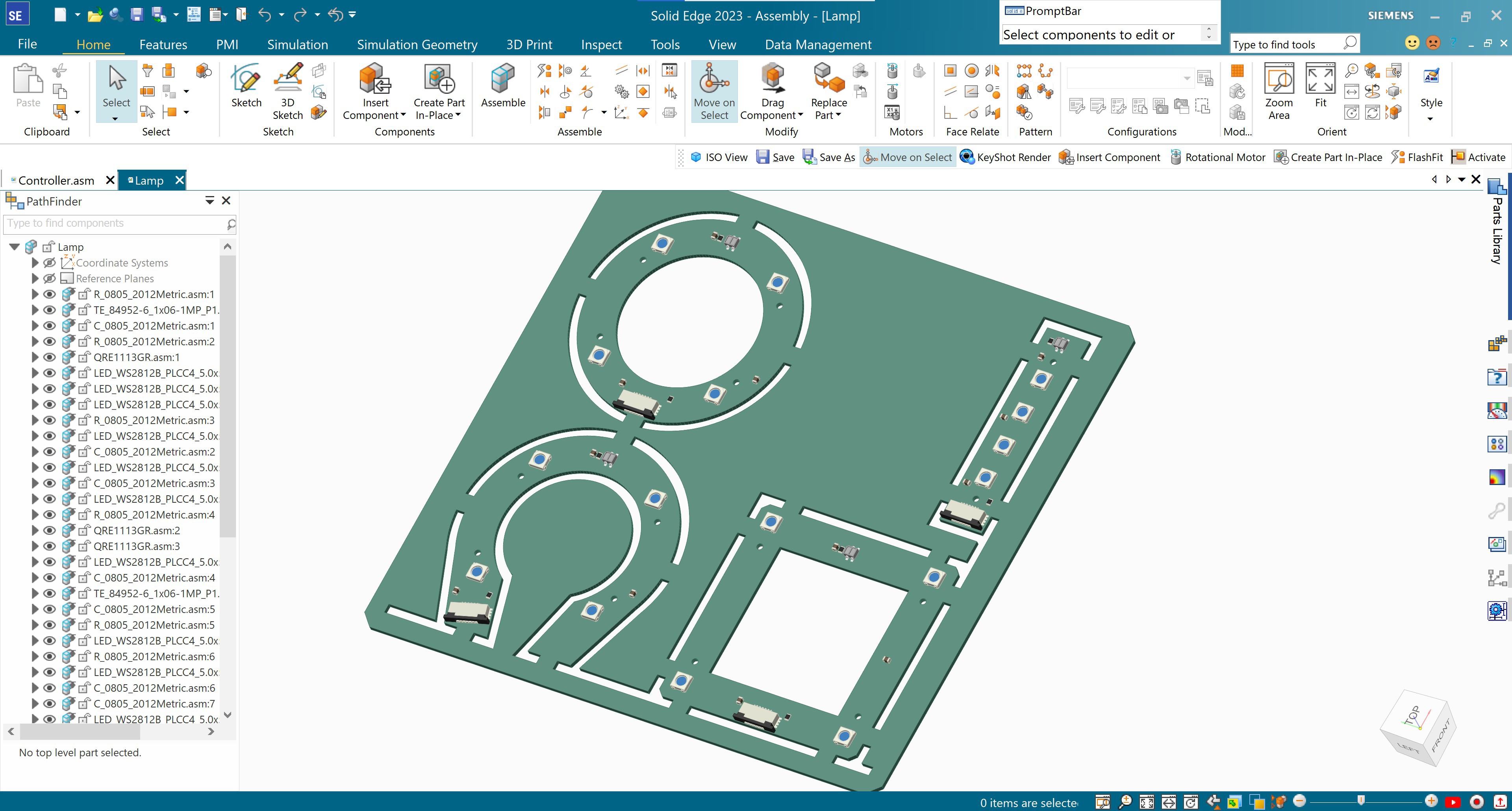
There is only one Controller Board shape. this is where the BLE Sense and batteries are located. However, your design will inform where the battery holders are placed. Please do not solder the battery holders to the board until you have read all the remaining steps! There are a few important considerations to define first.
![]()
-
2Controller Board
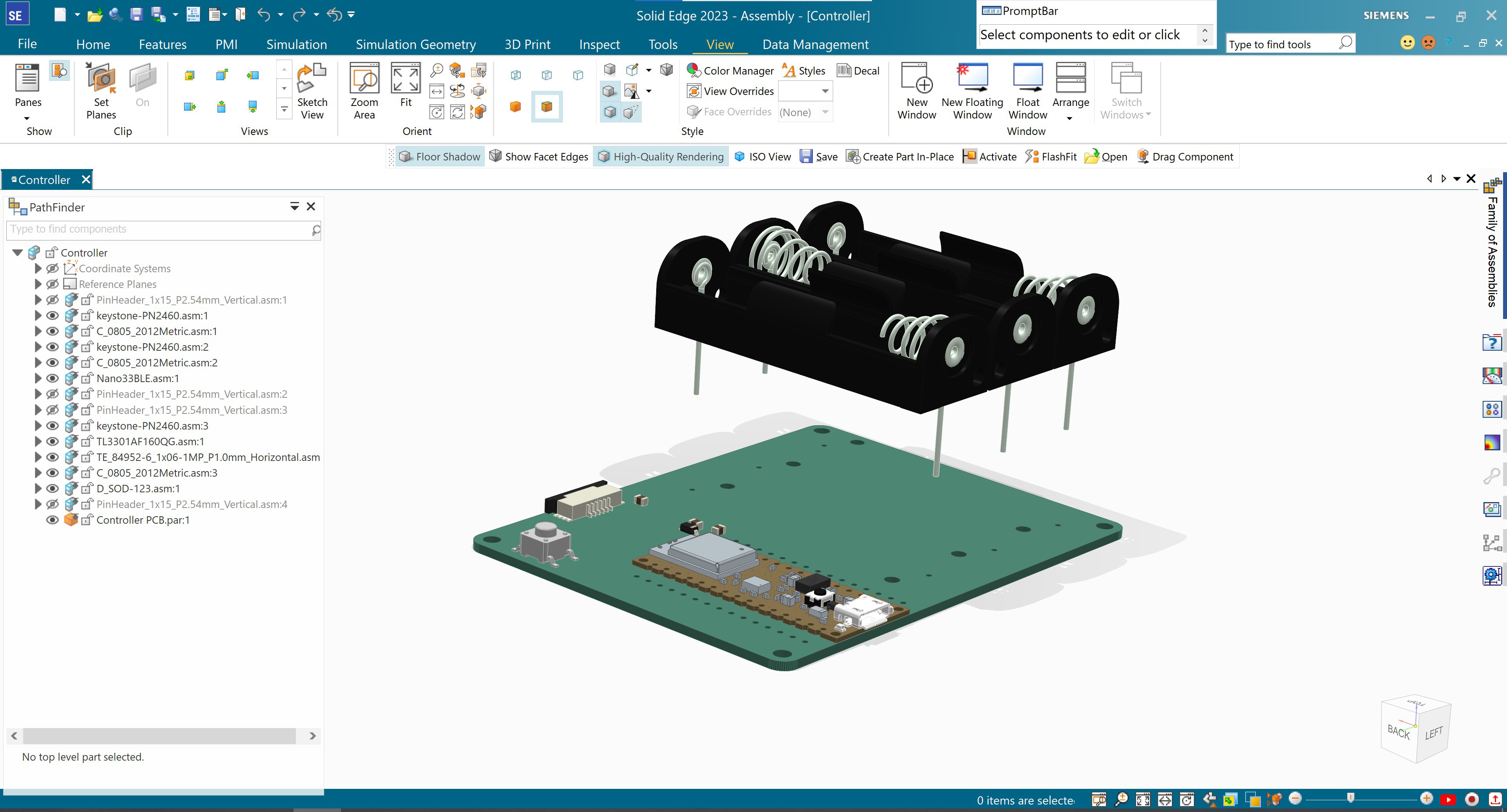
The Controller Board has a few important components and attributes to be aware of when designing your Lamp project.
- The Arduino Nano 33 BLE Sense Rev2. This phenomenal development board is jam-packed with sensors and other goodies that will add new depths to this and future projects of yours. It is really recommended that you read a bit about its fantastic capabilities. More on that later. For now, we will mention that it comes with: Bluetooth, motion detection, microphone, proximity and gesture detection, barometric pressure detection, temperature and humidity sensors., micropython support, and it features a nRF52840 microcontroller.
- 3 'AA' battery holders. Ideally, these should be easily reachable. Batteries may be rechargeable or non-rechargeable.
- Ribbon cable connector.
- USB mini port. Your design will determine if this port has to be accessible at all times or not. However, we will use it to flash (upload) firmware to the microcontroller.
Assembly holes and precise dimensions can be found in the AI and 3D STEP files.
+ + + IMPORTANT + + +
Before soldering the battery holders and Arduino BLE Sense, take some time to define your design. Does it make more sense to put the batteries on the same side as the Arduino? Is it best to keep them separate?
![]()
-
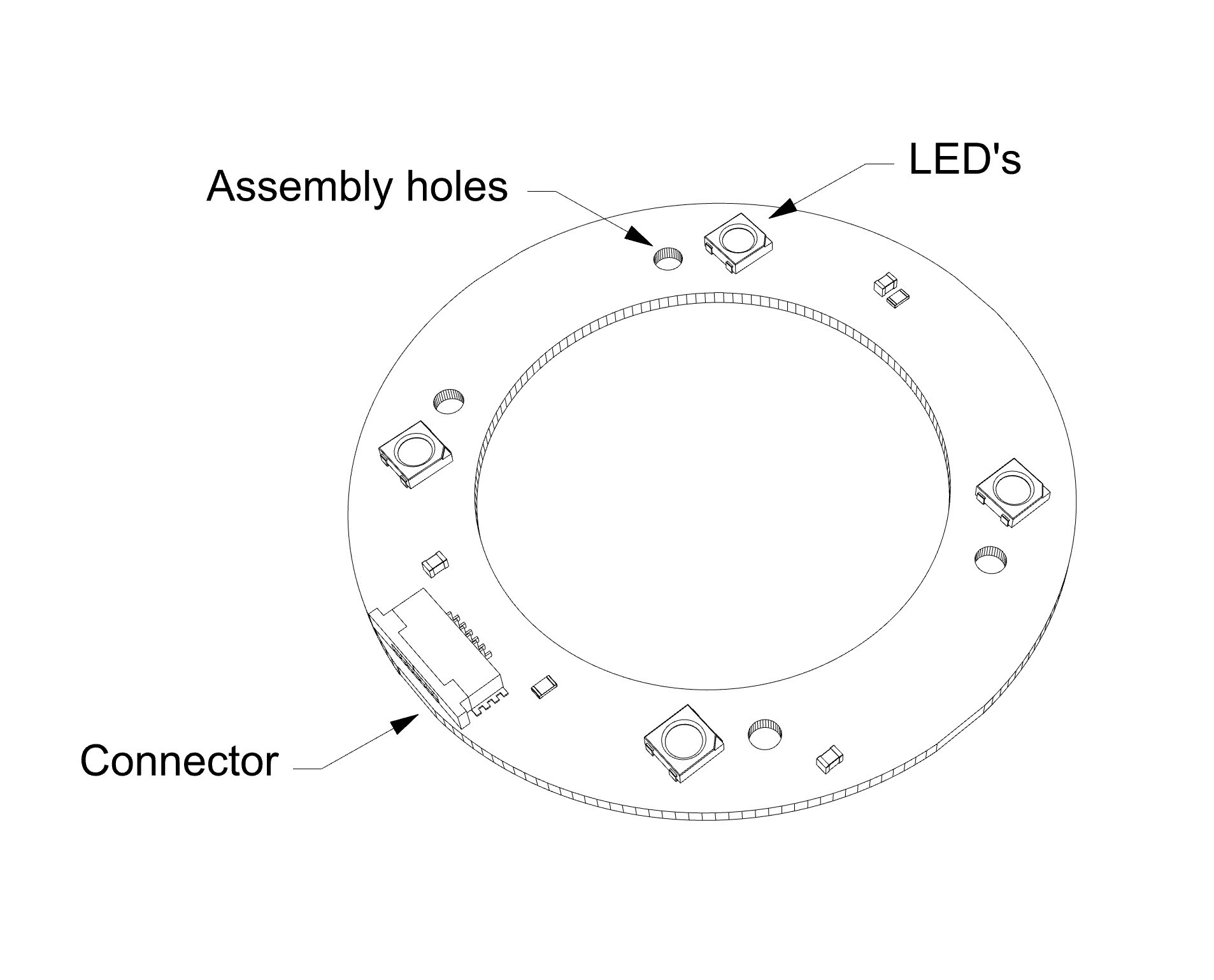
3Lamp Board
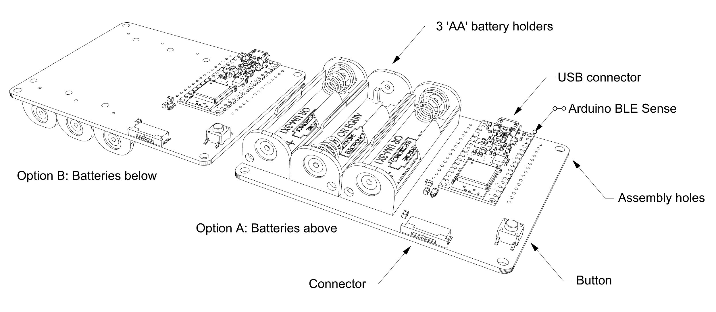
As mentioned earlier, all Lamp Boards have the same components. Here is a quick overview, before we go into more detail:
- Four addressable RGB LED's. RGB means that they can cast Red, Green, Blue light, and everything in between. Addressable means that each one can be operated separately.
- Four assembly holes.
- One ribbon cable connector. This cable supplies power and sends and receives data to and from the Controller Board.
Just like the Controller Board, assembly holes and precise dimensions can be found in the AI, and 3D STEP files.
![]()
-
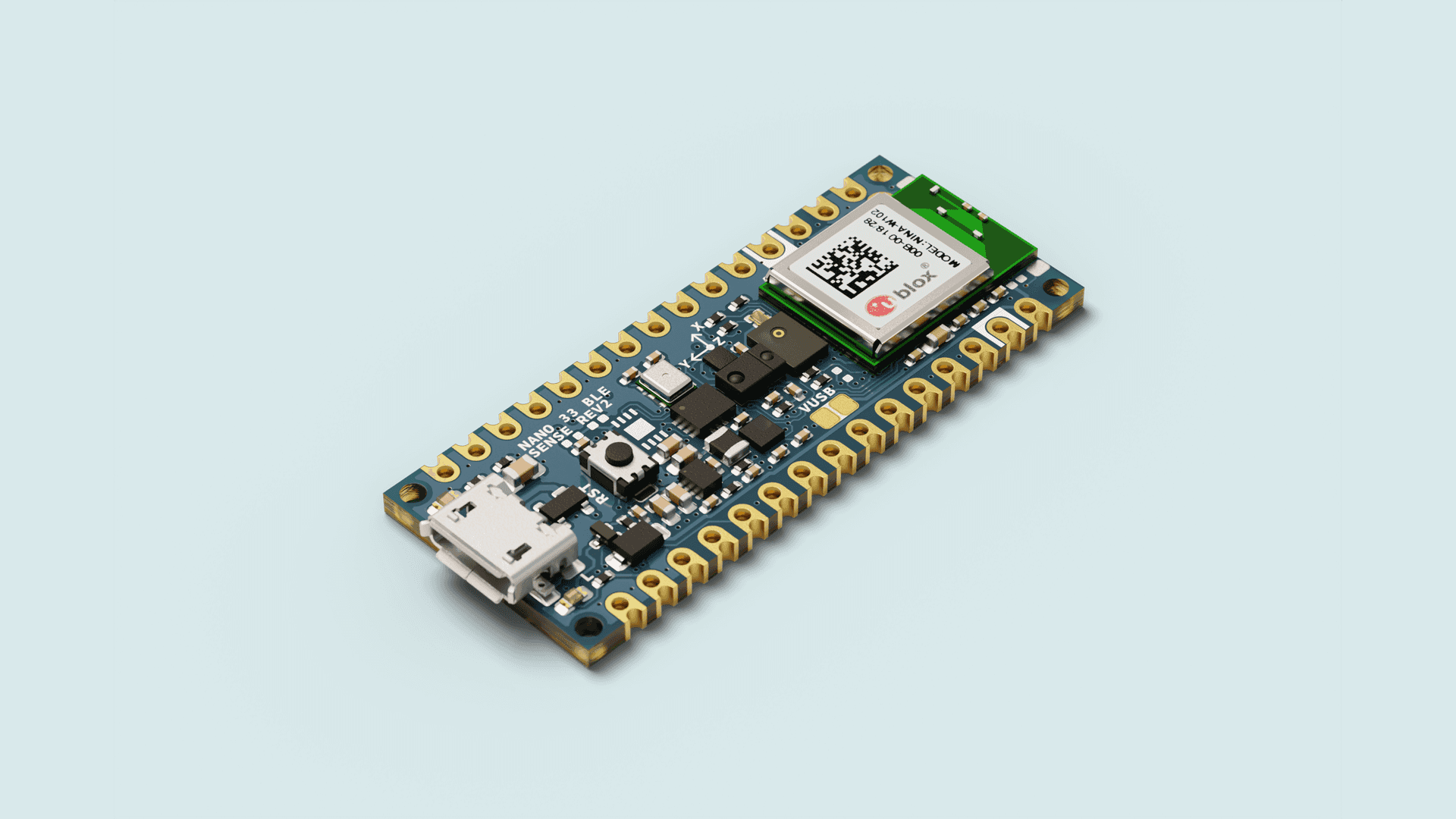
4BLE Sense Rev 2
Let's talk a little bit about the main board, its microcontroller and sensors, and why they all are relevant.
Development Board
The Arduino BLE Sense Rev 2 that we are using can be considered a development board, meaning that hardware designers use it to iterate concepts quickly for projects, products o experiments. Think of development boards as "mini electronics workshops". Some have more bells and whistles than others. There are many kinds, but in general, in addition to the microcontroller, they provide connectors, power source, and built-in components for specific functions, all in a standard shape.
![]()
Image credit: Arduino Microcontroller
The microcontroller in a development board is the actual brain of your whole array. The more complicated a system is (for instance, a robot), the more "minibrains" you will need. Microcontrollers are small computers that perform one task at a time, but they do it quickly and efficiently, thus not needing as much computing power or energy, as say, a microprocessor of a computer that has to deal with graphic interface, sounds, connections, etc. The BLE Sense Rev.2 uses the nRF52840, and here is its data sheet in all its 619 pages glory.
Impact on your product
The microcontrollers that we discussed above can be bought separately and put in your own Printed Circuit Board. However, their architecture may be different, and the code used in one may not work on the other. You may be very happy and jolly working on a project with a development board that you love, only to find out that there is no stock of its particular microcontroller, and the lead time is long. Those are some of the few reasons that you need to keep in mind when selecting a development board.
-
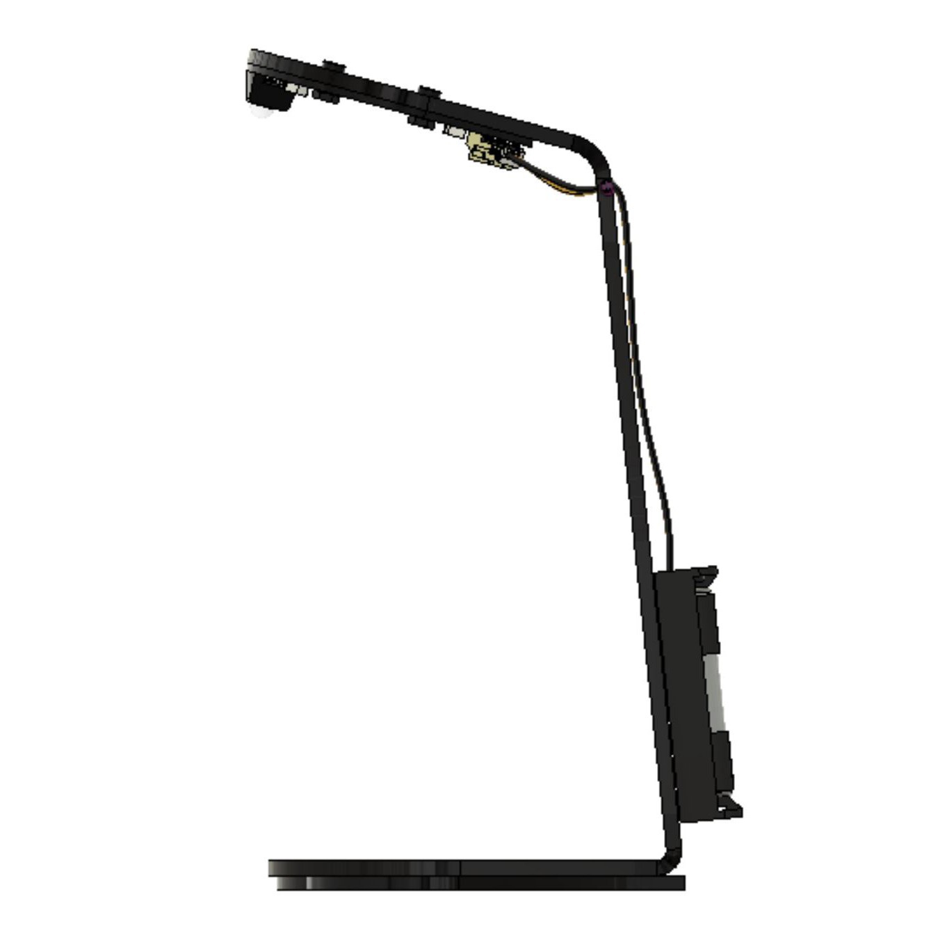
5Product Design Inspiration
This workshop was derived from the original PCB Lamp.
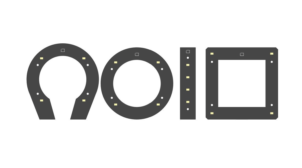
The project has become more interesting every time, and this time around, the participants of the workshops define how the Lamp will look like, and its core functionality! Participants will be able to choose between four shapes for the lighting element. The controller is the same.
![]()
If you study(ied) design or are an enthusiast, you will probably recognize a pattern here. These shapes took a bit of inspiration from Bauhaus' study of shapes. Now, between you and me, we did make a triangle PCB but it did not add that much. So, we kept the circle, a square, and added two more forms: a straight line, and the "horseshoe" shape from the previous workshop.
Functionality
For this Arduino Edition of the workshop, the lamp will be activated using the sensors found the in the BLE Sense. How, specifically? Well, we put together some code to start using the BLE's sensors, but we will leave it up to you to modify it. This is the cool thing about code: you determine how the lamp turns on, for how long, what colors, etc. For more on that, see you in steps 7 and 8.
-
6Recommended tools for the workshop
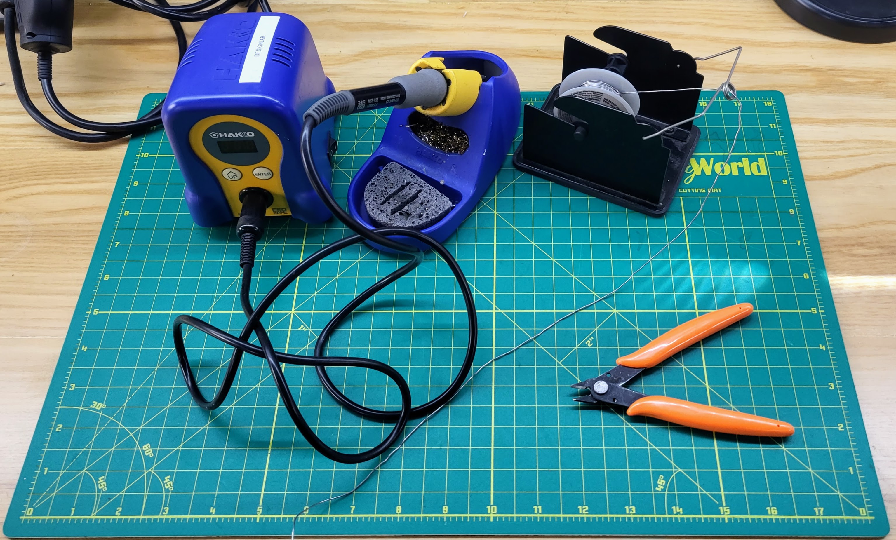
Provided that you have the PCBA kit and the lamp body that you designed, you only these tools:
- Soldering iron
- USB to USB micro cable
- 3 AA batteries
- Solder
- Wire cutters. We recommend precision diagonal cutters with tapered head
![]()
If you are taking this workshop at the DesignLab, to fabricate your lamp body you may use:
- Laser cutter,
- CNC mill,
- CNC router,
- 3D printers
- Wood shop tools
Anything except for the laser cutter would take more than one session to make, so please reach out in advance to see how we can fabricate your parts. Also, some tools need special training before using.
-
7Arduino sketches
This workshop comes with a number of Arduino sketches ready for you to load and start playing with the parameters. Simply go to Files and choose the one of your liking!
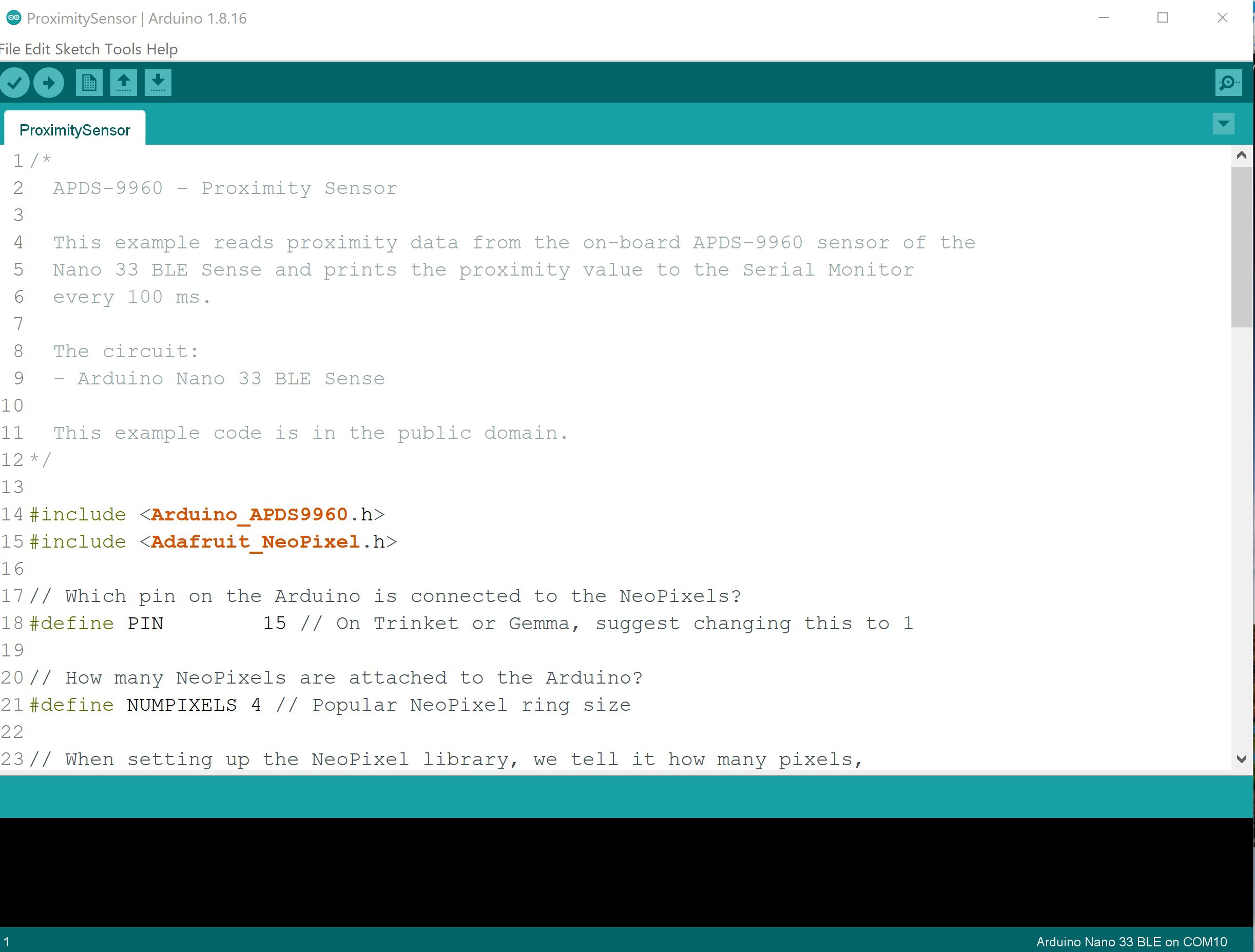
Once you have Arduino IDE installed on your computer, you may open the .ino file and start working with it or flash it directly to your board. Or, you can copy the text and paste it onto another screen.
The available sketches or code interact with several of the BLE Sense's sensors and the Controller Board's available. There are sketches for use with the microphone, color sensor, proximity sensor, gesture sensor, and the accelerometer.
![]()
-
8Arduino IDE
To download Arduino IDE in your computer, please go to https://www.arduino.cc/en/software and download the latest version of Arduino IDE that works with your operating system.
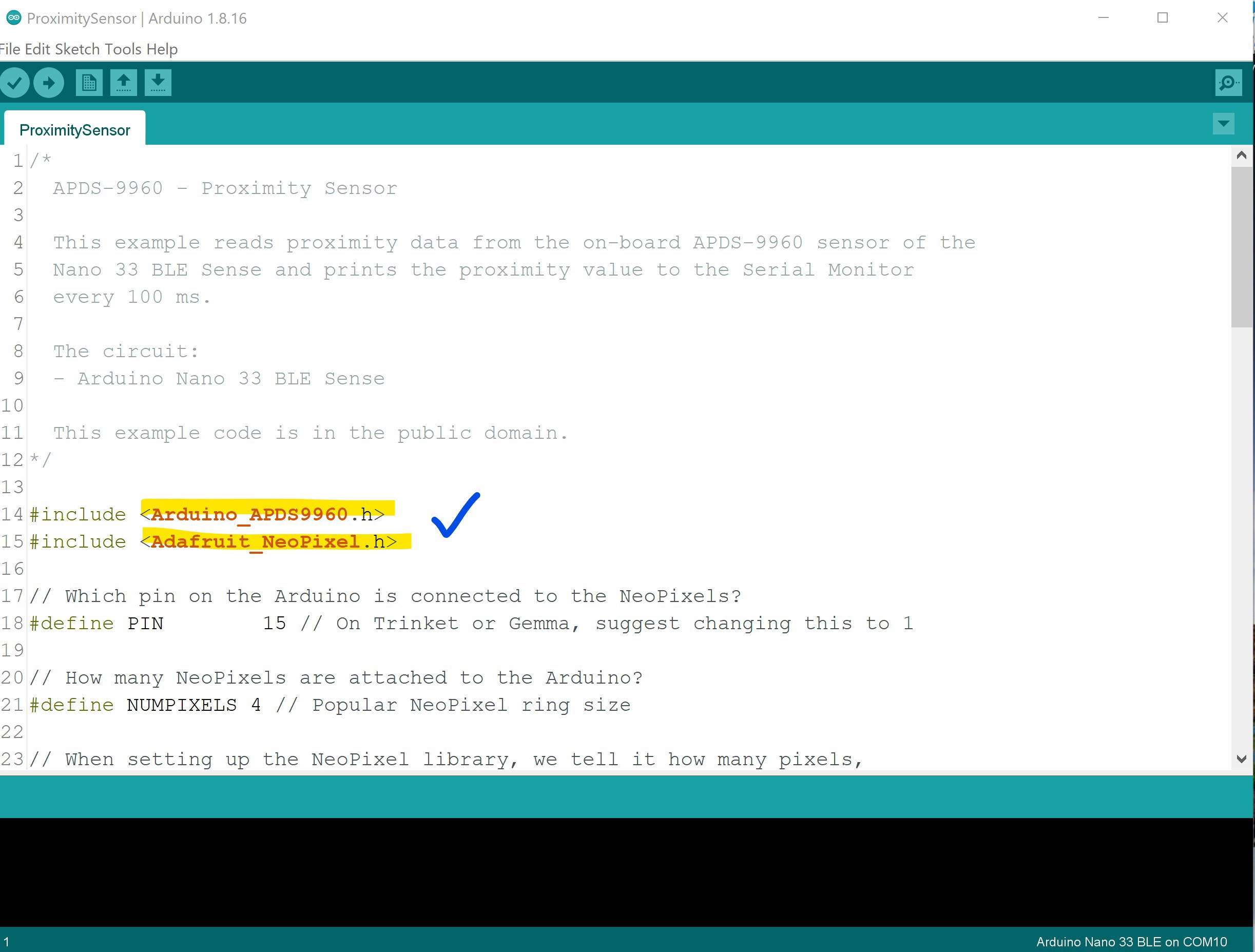
Some of the sketches (or code) that we created require additional libraries. Think of libraries as "instant knowledge" for your code. With certain libraries, your code will be able to handle different things. The specific libraries for each sketch are in the code, after #include.
![]()
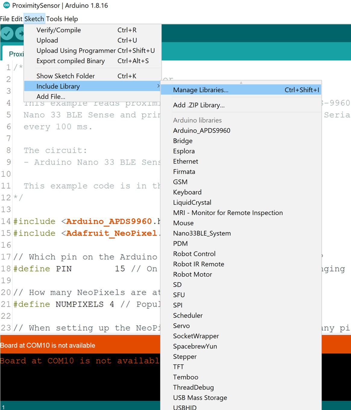
How to download the libraries? Very easy! Just go to Libraries > Manage Libraries.
![]() With a few keywords, you will find the right ones.
With a few keywords, you will find the right ones.![]()
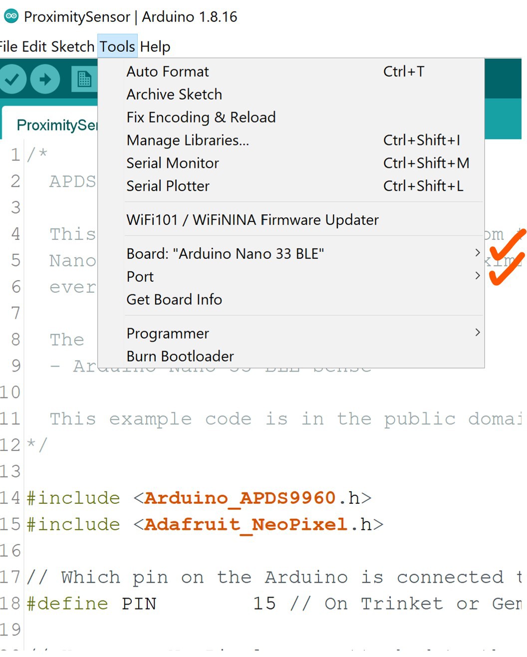
To be able to flash the firmware to your boards, make sure that you have the correct Board and Port selected.
![]()
A very good indication whether your board is working properly or not is the Serial Monitor under Tools. If your board is working and reading information from the environment, then this should be refreshing data constantly. Don't forget to close it before flashing any updates!
![]()
PCB Lamp Workshop - Arduino Edition
Components and instructions to create your own touch-activated lamp, and learn about product design, hardware and firmware.
 With a few keywords, you will find the right ones.

Discussions
Become a Hackaday.io Member
Create an account to leave a comment. Already have an account? Log In.