mircemk
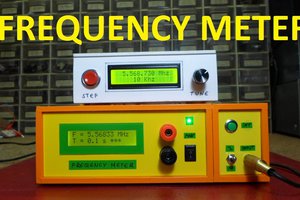
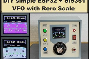
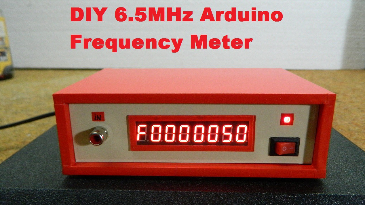
 A frequency meter, also known as a frequency counter, is a device or instrument used to measure the frequency of an oscillating signal. Frequency meters can come in different forms, ranging from simple handheld devices to sophisticated laboratory equipment. The frequency meter presented in the video displays the frequency in digital form, on a retro look 7 segment display module with 8 digits. In one of my previous videos I presented a way of making such an instrument using an Arduino that had a measurement range of 0 to 6 MHz.
This time the frequency meter uses an inexpensive STM32 microcontroller and this time, thanks to his better perfomances of the MCU, the frequency range is from 0 to 30 MHz, and therefore it is ideal for use in HF radio devices .
The code is taken from the rcl-radio site )where you can view the original project. I left out the input part of the original project for the sake of simplicity and now the input signal can range from 0.5 to 3V. We can simply increase this range with a voltage divider at the input, consisting of two resistors.
If you want to make a PCB for your electronic project, PCBway is a great choice for you. PCBway is one of the most experienced PCB manufacturing company in China in field of PCB prototype and fabrication. They provide completed PCB assembly service with worldwide free shipping , and ISO9001 quality control system. Also, on their site there is an online gerber viewer where you can upload your gerber and drill files to render your board.

Otherwise, STM32 is a 32-bit ARM microcontroller developed by STMicroelectronics, and Arduino Bootloader can be installed on it, and it can be used as a standard Arduino. The Arduino IDE application can be used for writing, compiling, and uploading code to microcontroller board. This time we will not dwell on the method of installation and uploading the code, because we can find many detailed tutorials on the Internet, such as this one (https://www.instructables.com/Using-a-STM32-Like-an-Arduino-Tutorial-STM32F103C8/).
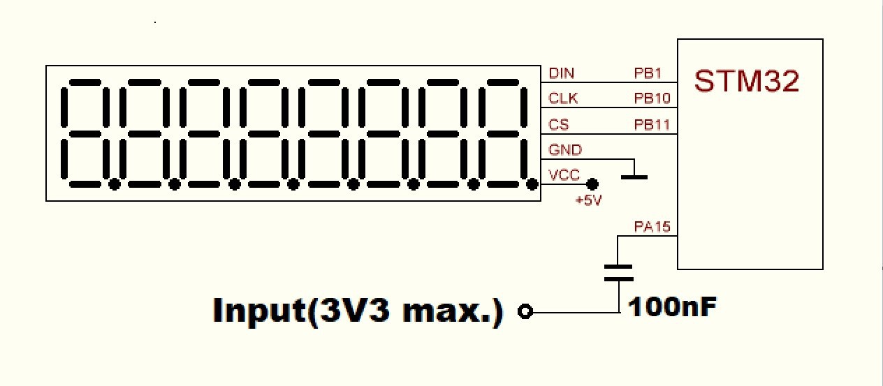
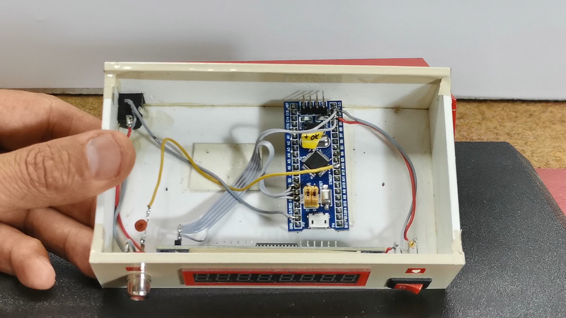
The device is really simple to build and consists of several components
- STM32F103C6 or STM32F103C8 microcontroller board
- 8 Digit 7 Seg Display module
- and one 100nF capacitor
And now let's test the device in real conditions. First we will use this rectangular signal generator for which you can find instructions for making in one of my previous videos.
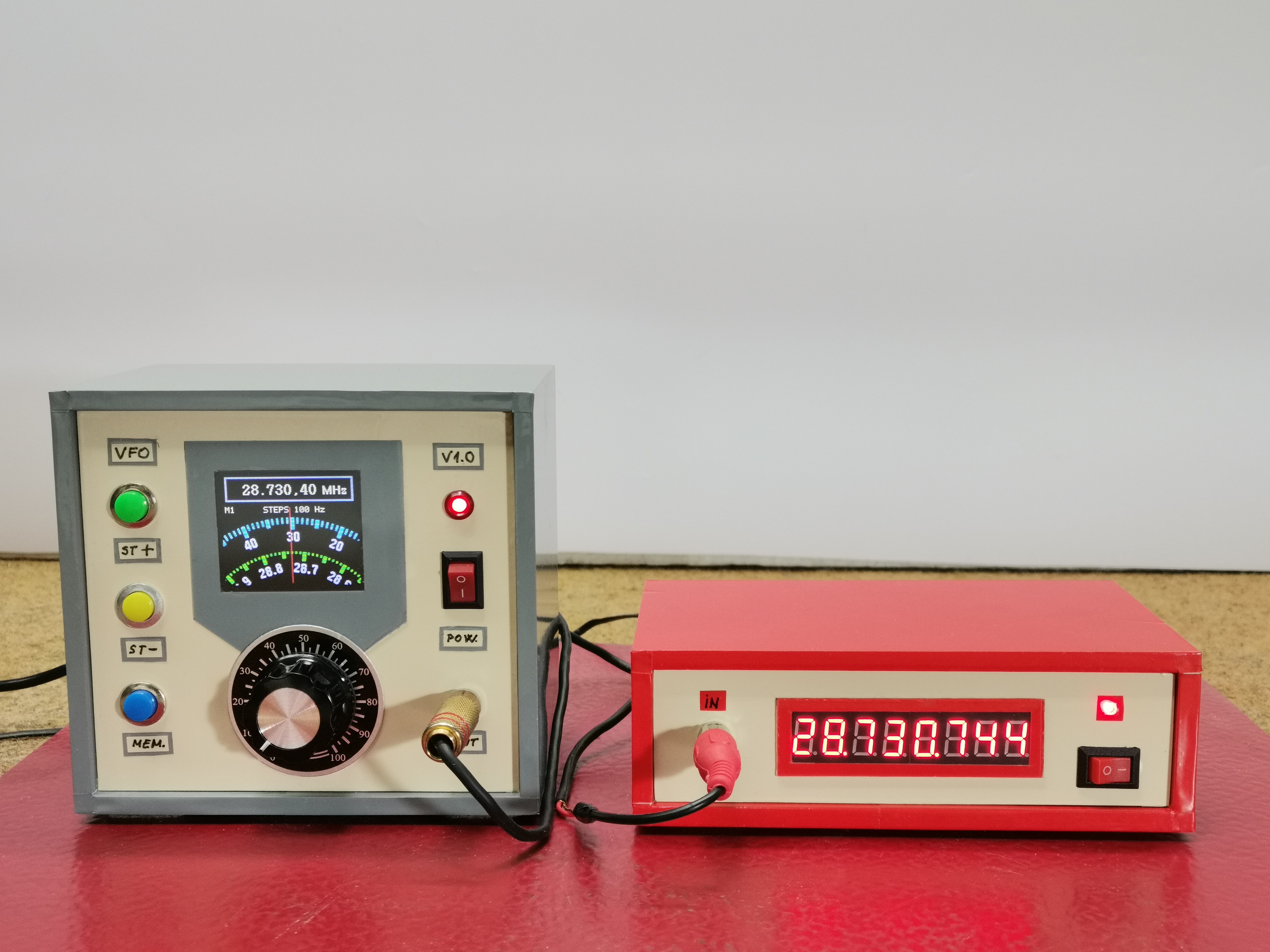
As can be seen, the frequency of the generator and the frequency meter differ by a hundred Hertz at 30 Megahertz, but since this is not a laboratory professional device, we do not know whether the fault is with the generator or the frequency meter. However, this is a very small difference and can be ignored. Otherwise the frequency meter can be roughly calibrated in the code line:
TIMER1_BASE->ARR=36000;
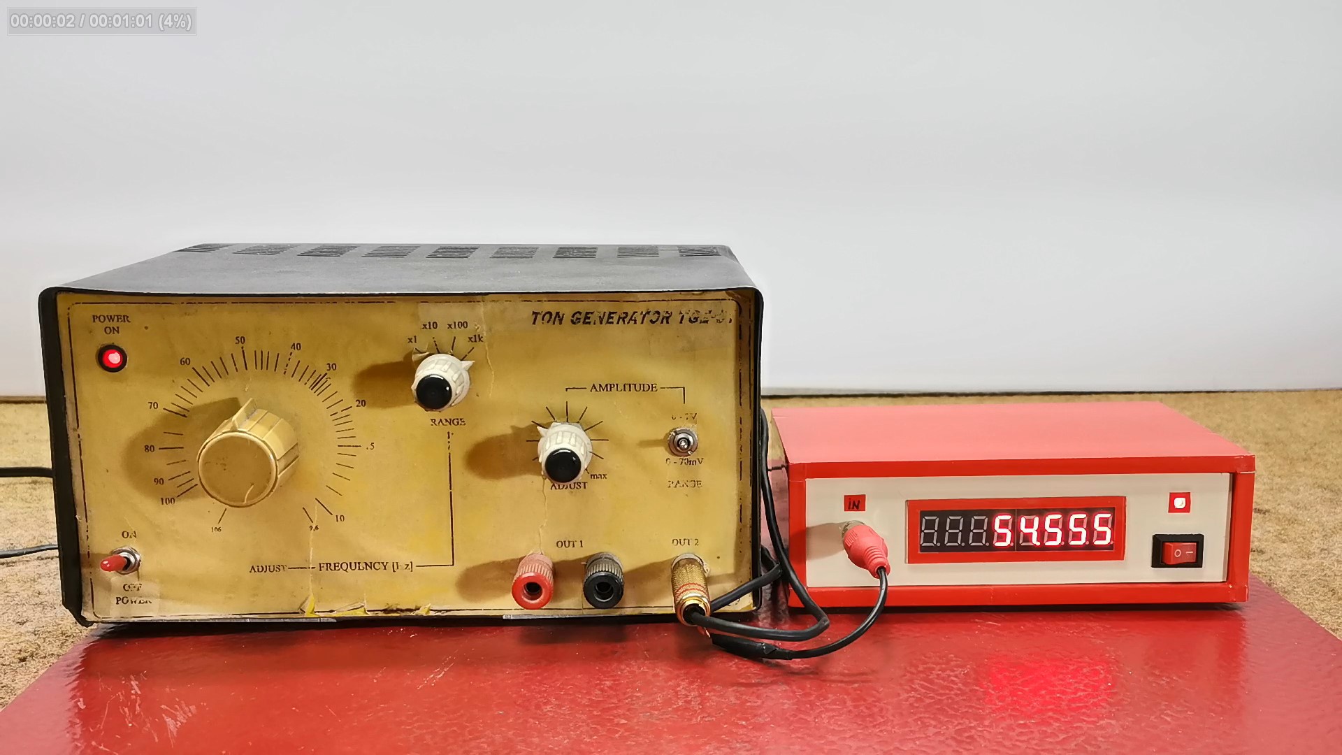
Next I will measure the frequency of the sinusuidal signal at the output of this old Tone Generator.
And finally a short conclusion. This is an incredibly inexpensive measuring device, the total cost of which does not exceed a few dollars, and is an indispensable instrument in any laboratory. For reliability and universality, it is necessary to add a simple passive or active circuit to the input to increase the input voltage range. The device is embedded in a suitable miniature box made of PVC material and lined with self-adhesive colored wallpaper.