 mircemk
An oscilloscope, often referred to as an "scope," is a test instrument used to visualize and analyze the waveform of electronic signals. It is an essential tool for engineers, technicians, and researchers working in fields like electronics, telecommunications, physics, and more.
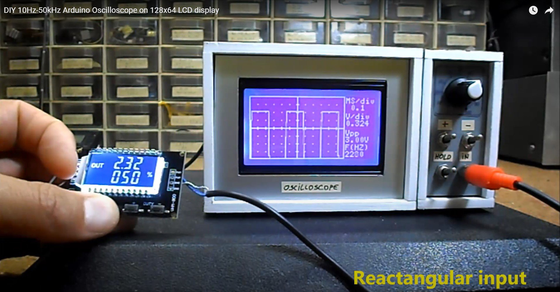
In some of my previous videos I described how to make a digital oscilloscope using Arduino, which has a maximum frequency range of up to 50kHz.
This time I will present you a more advanced oscilloscope with STM32 Microcontroller which has better performances than Arduino and is also cheaper. With this instrument we can now observe the shape of signals with a frequency of up to 500КHz. You can see the original project on the RCL-Radio site.
Otherwise, STM32 is a 32-bit ARM microcontroller developed by STMicroelectronics, and Arduino Bootloader can be installed on it, and it can be used as a standard Arduino. The Arduino IDE application can be used for writing, compiling, and uploading code to microcontroller board. This time we will not dwell on the method of installation and uploading the code, because we can find many detailed tutorials on the Internet, such as this one.
If you want to make a PCB for this project, or for any other electronic project, PCBway is a great choice for you. PCBway is one of the most experienced PCB manufacturing company in China in field of PCB prototype and fabrication. They provide completed PCB assembly service with worldwide free shipping , and ISO9001 quality control system. Also, on their site there is an online gerber viewer where you can upload your gerber and drill files to render your board.

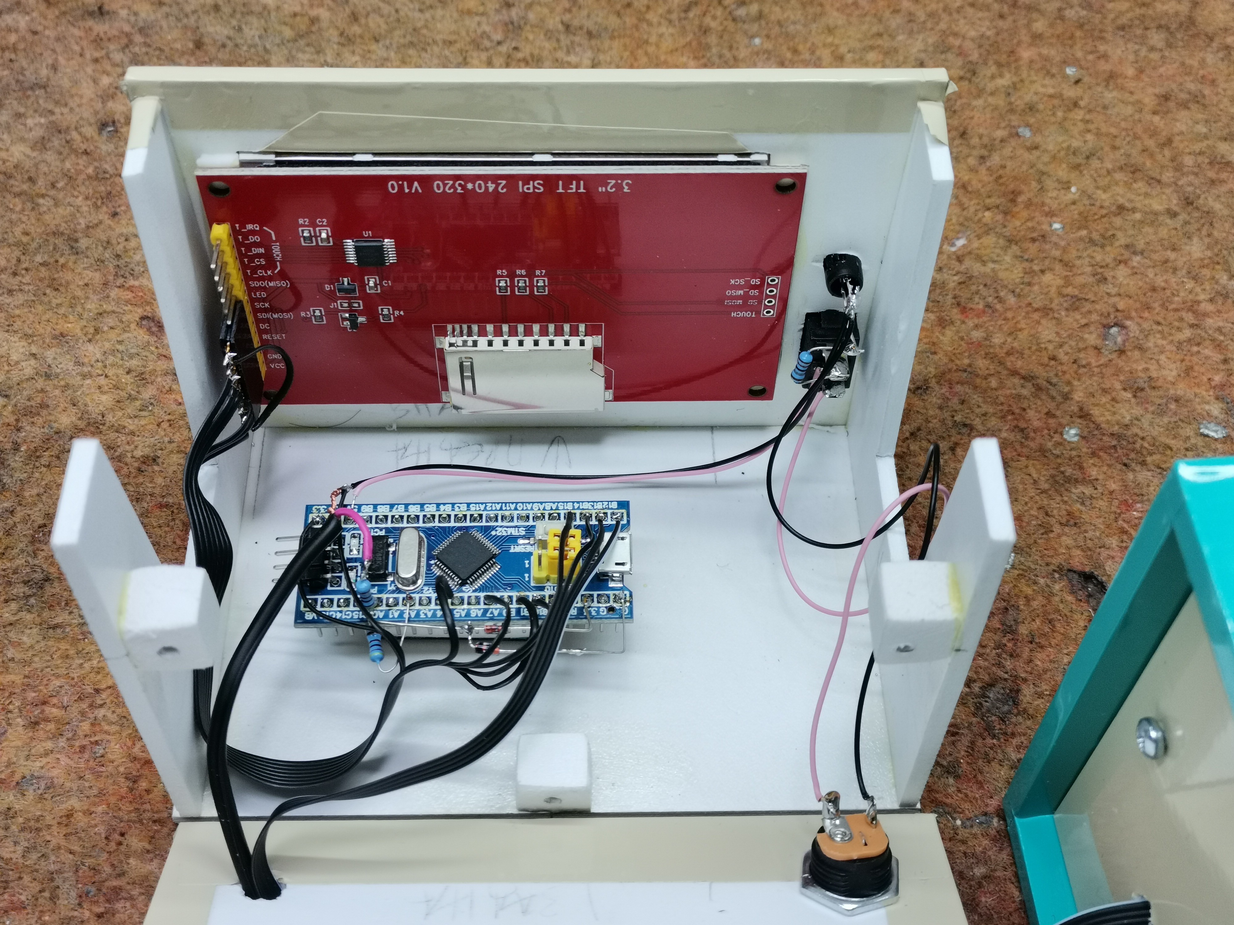
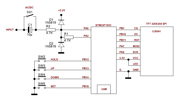
The device is extremely simple to make and contains only a few components
- STM32F103C8T6 Microcontroller
- 3.2 or 2.8 inch TFT color display with a resolution of 240 by 320 points powered by the ILI9341 chip
- two diodes
- two resistors
- and five buttons
The maximum input positive voltage is 6.6 V and can be increased by using an external voltage divider. If the device is made according to the given schematic diagram and code, it works immediately after the first power-on without any previous setting in the code or libraries.
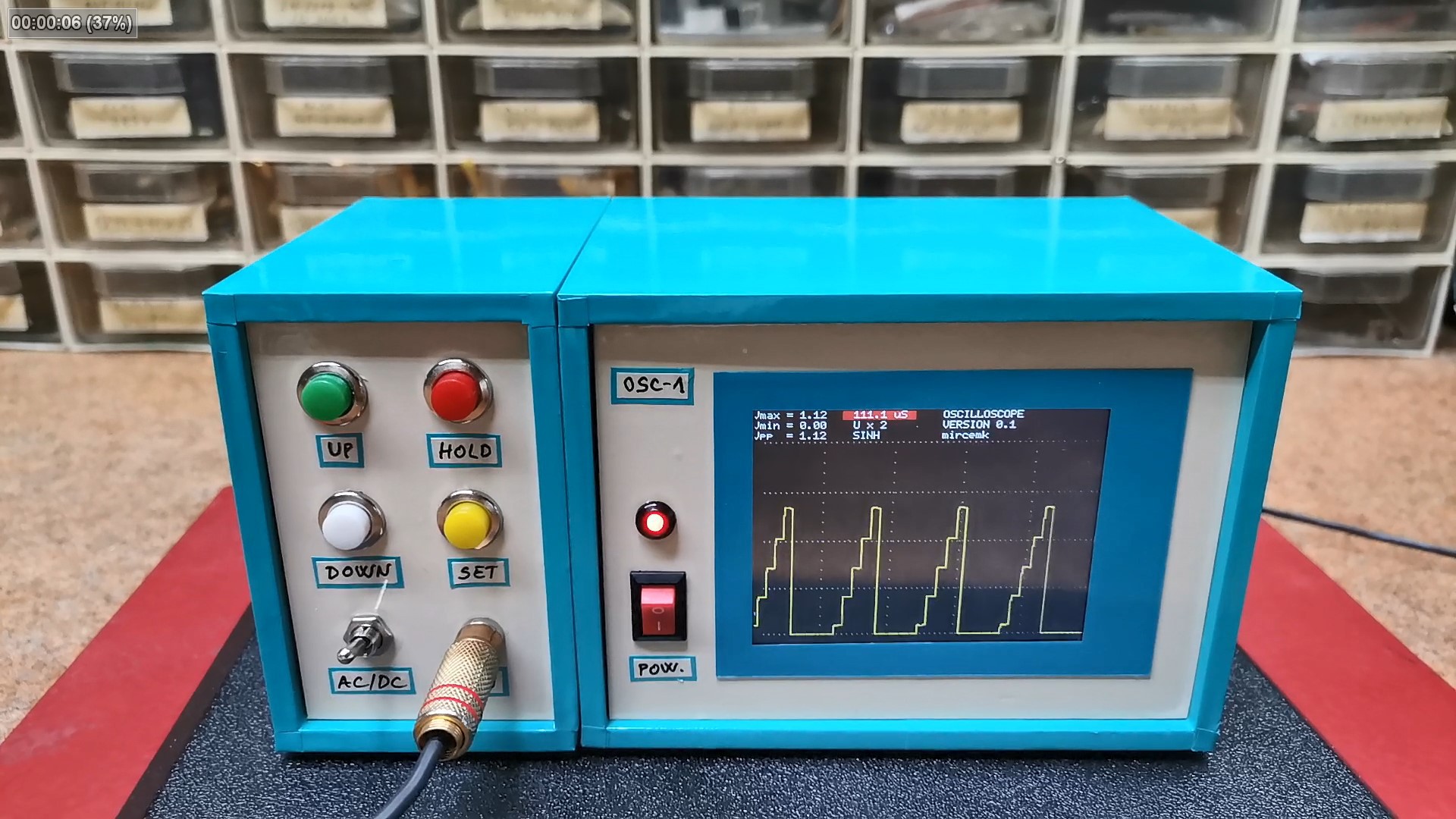
Let's first explain the function of the buttons:
- With the SET button we enter a menu where we can change more settings
- Up and Down buttons are used to change the value of the selected function
- The Hold button serves to freeze the current image of the signal for further analysis
- and with the AC/DC switch we select the type of input signal
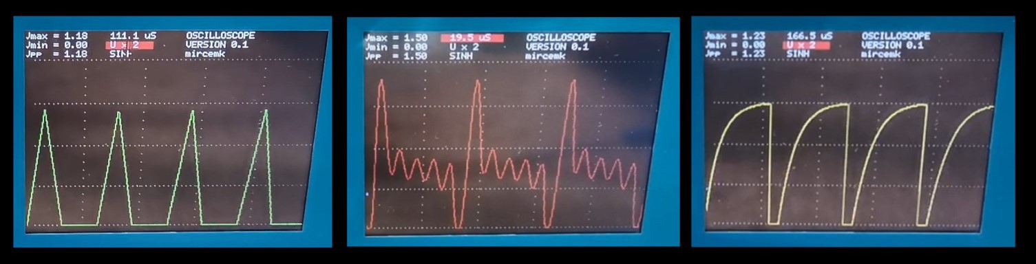
In the upper left part of the screen, the amplitude value of the signal is given, followed by the sweep duration. When the Hold button is activated, we have additional functions for analyzing the input signal.
As you can see in the video, the colors of the curve can be changed very easily in the code in line:
tft.drawLine(i*mn, 230-data1[i+i2],i*mn+mn-1, 230-data1[i+1+i2], ILI9341_RED);i++;}i=0;
And finally, a short conclusion. Unlike the previous oscilloscopes with Arduino, this device, due to its frequency range and speed, represents a relatively serious functional instrument that can find a place in any laboratory, and at the same time, the price for its making is extremely low, no more than 15 dollars. The oscilloscope is installed in a suitable box made of PVC material with a thickness of 3 and 5 mm and covered with self-adhesive colored wallpaper.


 Deepak Khatri
can we make the same project with esp32 or 28, i have an stm32 board couldn't work im so sade