 Michael Gardi
In order to get accurate tile readings, it's important to calibrate the linear hall effect sensors. I found with my TMD-3 project that for the best results each sensor should have its own calibration values for each of the possible tile variations. With 16 sensors and 10 possible tile variants this can be a pretty tedious process. So to make things easier I create a calibration sketch. NOTE that you only have to do this calibration once.
To start I create a special set of calibration tiles.
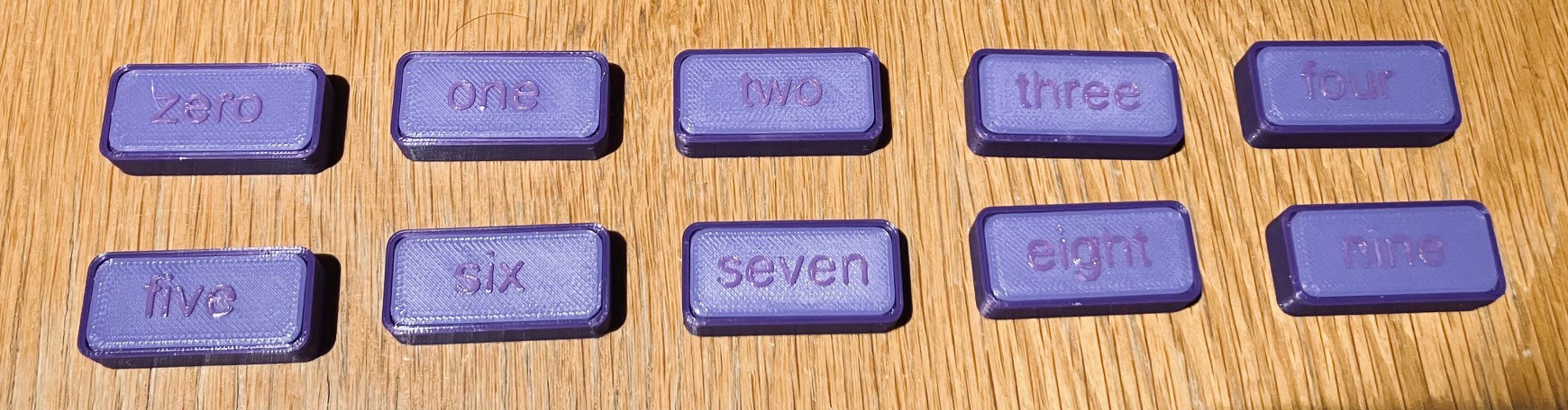
Each tile contains two magnet holders set to the number that appears in the label.
The calibration program runs from the Arduino IDE and outputs to the Serial monitor. With NO tiles in the MacroPad when the program first starts up you see the following:
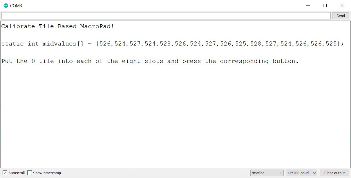
The midValues array printed represents the "at rest" or no magnet present readings from the hall effect sensors. Notice that the values do not vary much between sensors. This table should be copied into the MacroPad sketch replacing the existing table with freshly calibrated values.
Following the prompt, when you put the "zero" tile into each of the eight slots and press the corresponding buttons, you should see something like:
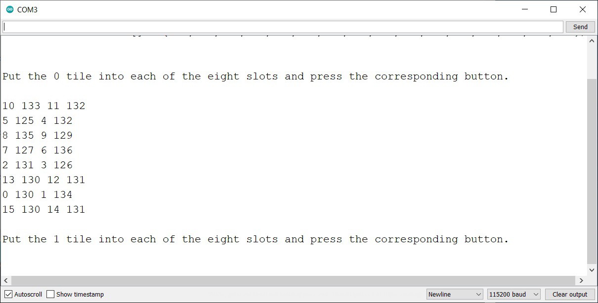
For each button pressed the two sensors for that button are read and the sensor numbers and values are emitted. When all eight slots have been calibrated the next tile number is asked for.
When all ten tiles have been calibrated the calValues table is emitted.
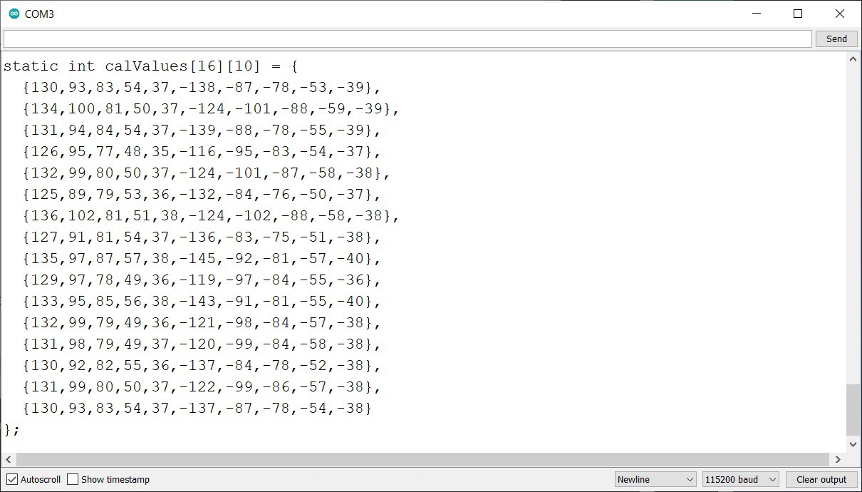
Simply cut the table text from the Serial window and paste it into the MacroPad sketch replacing the existing table.
The MacroPad should now be setup to accurately read tiles and correctly map them to the defines macros.
I have posted the Calibrate_MacroPad.ino sketch to GitHub.
Discussions
Become a Hackaday.io Member
Create an account to leave a comment. Already have an account? Log In.