 Michael Gardi
Overview
MacroPads have been a hot topic for years now as part of the tremendous continuing interest in custom keyboards. Search Hackaday for "macropad" and thanks in large part to Kristina Panos you will get pages and pages of blog entries with lots of cool designs (bananas and corn and sunflowers oh my). A similar search of Instructables returns 27 MacroPad results. With software like QMK or Kaleidoscope to ease the burden of creating and configuring the MacroPad firmware, and cheap microcontrollers like the Arduino Pro Micro or Raspberry Pi RP2040 this shouldn't come as a surprise to anyone.
The reason that I'm jumping into an already very busy category is that I think that a tile based interface solves a couple of shortcomings common to all MacroPads.
Labels/Legends
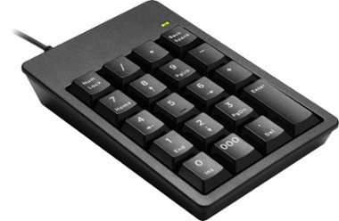
If the MacroPad is a simple add-on number pad, then it's easy to find keycaps with the appropriate legends to populate it.
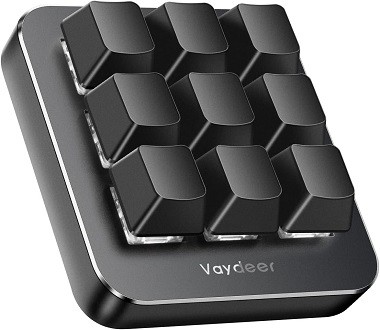
For MacroPads that are meant to be programmed with arbitrary user selected macros, then the legends become a concern. What does a "Check Inventory" button look like? Most commercial MacroPad offerings skirt the issue by shipping with attractively color coordinated blank keycaps leaving the user to memorize the function of each key.
There are other solutions. For instance, at the high end, from these very pages, "ADAPTIVE MACRO-PAD USES TINY OLED SCREENS AS KEYCAPS".
Cool except for the high per key cost and complexity.
Another simpler and cheaper solution is Relegendable Keycaps. The clear plastic caps allow you to create and insert printed text or icons.
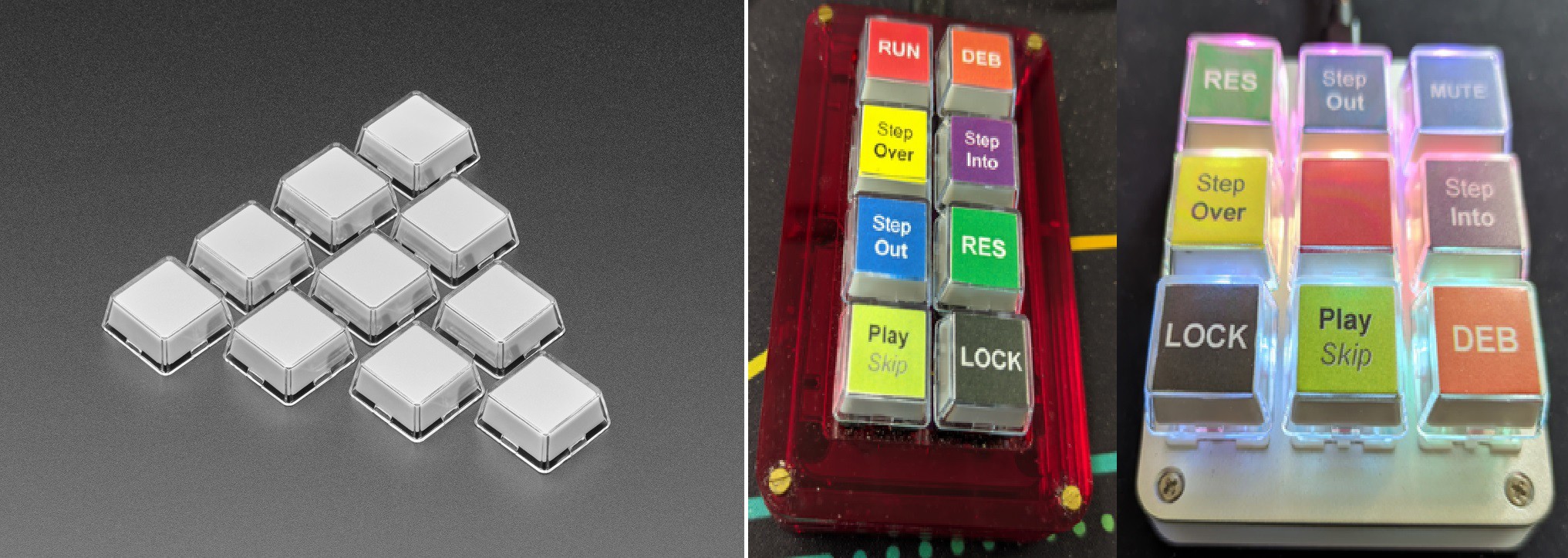
This is a pretty good solution, but it only works if the number of macros you want is less than or equal to the number of keys on the MacroPad. Which brings us to the second problem.
Many Macros/Few Keys
Once you begin using a MacroPad you start thinking about all the useful macros that you would like to use. You soon run out of keys to map the macros to. Configuration software like QMK solves this problem with layers. Layers allow the user to define multiple sets of macros for the keys available. Typically one key is assigned to switch between layers in one of the following manners:
- only for the next key press
- as long as the layer switch key is pressed
- till the toggle key is pressed again (there could be many layers)
One problem here is that a layer typically applies to all of the keys on the MacroPad. So when you switch the layer all of the key's macros change. Think of how this really exacerbates the legend issue. The user must remember all of the key macro assignments based on these hidden layers as the keycaps (except for the ones with tiny OLED screens) will be wrong.
So what is the solution?
A Tile Based Interface
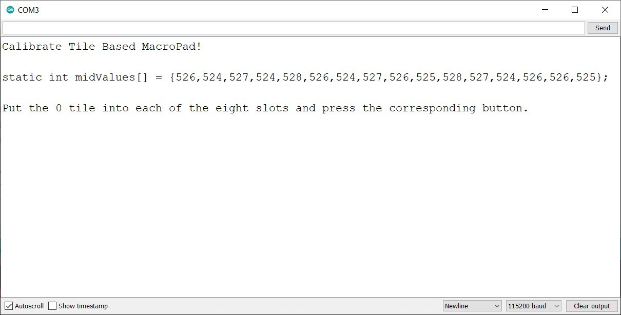
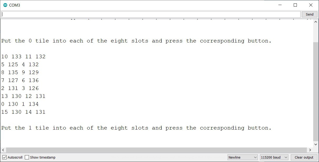
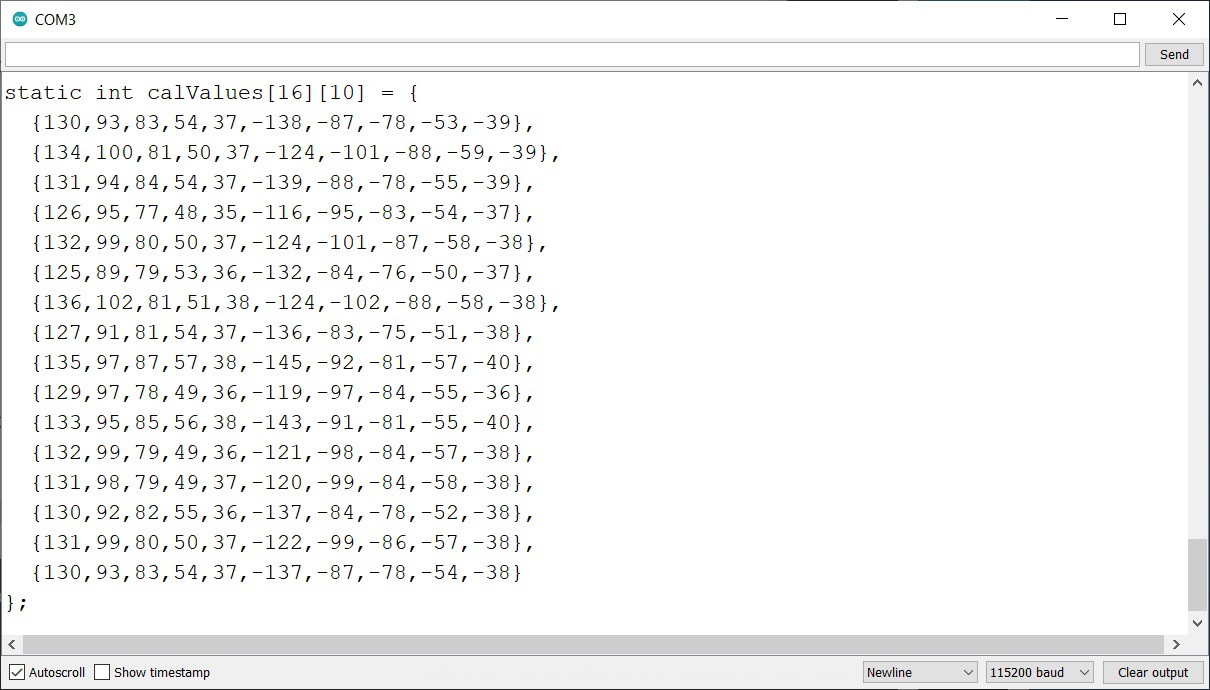
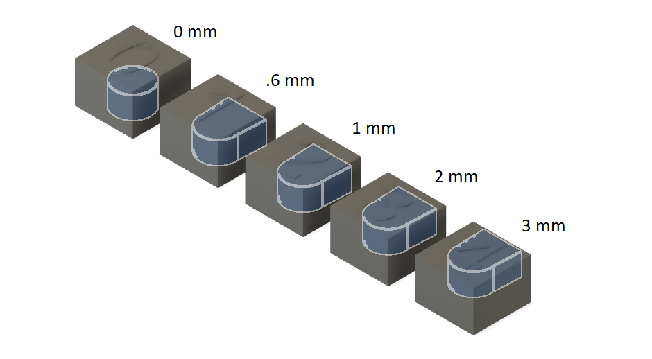
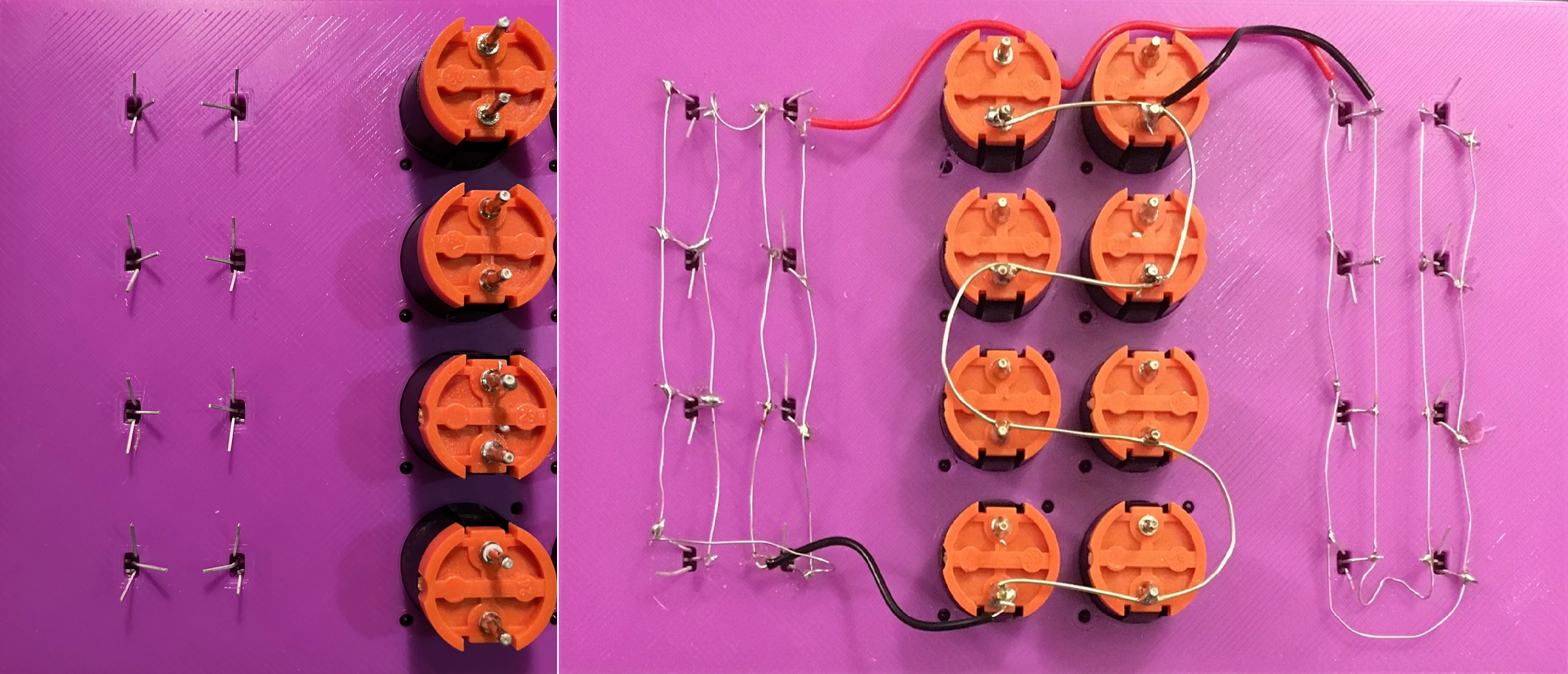
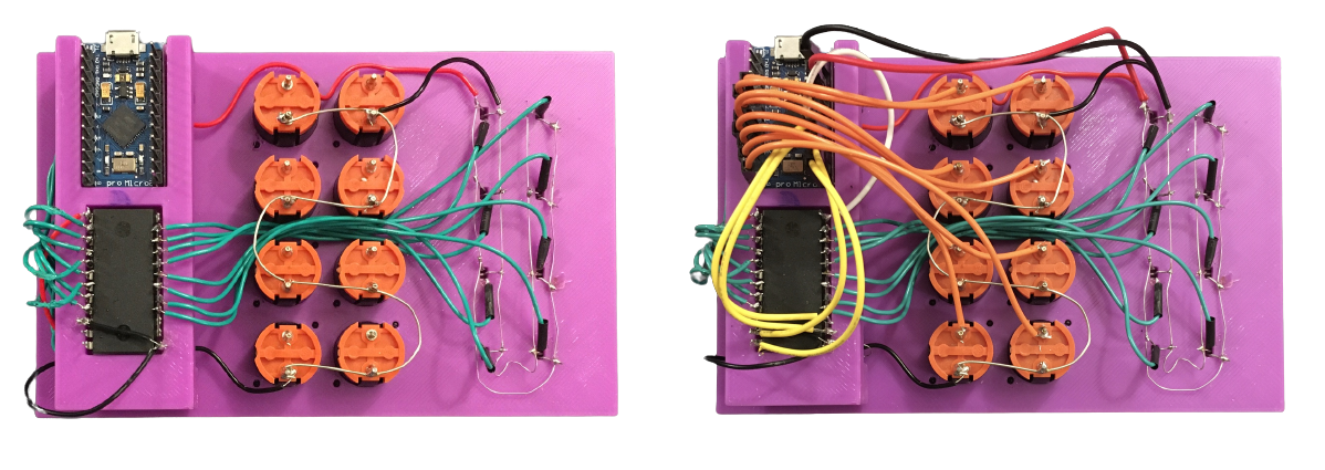
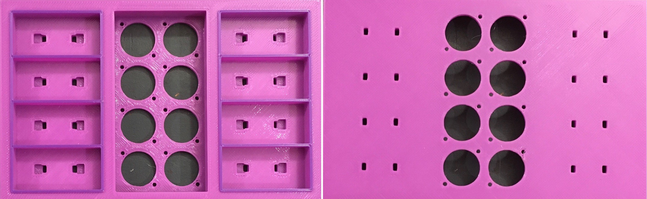
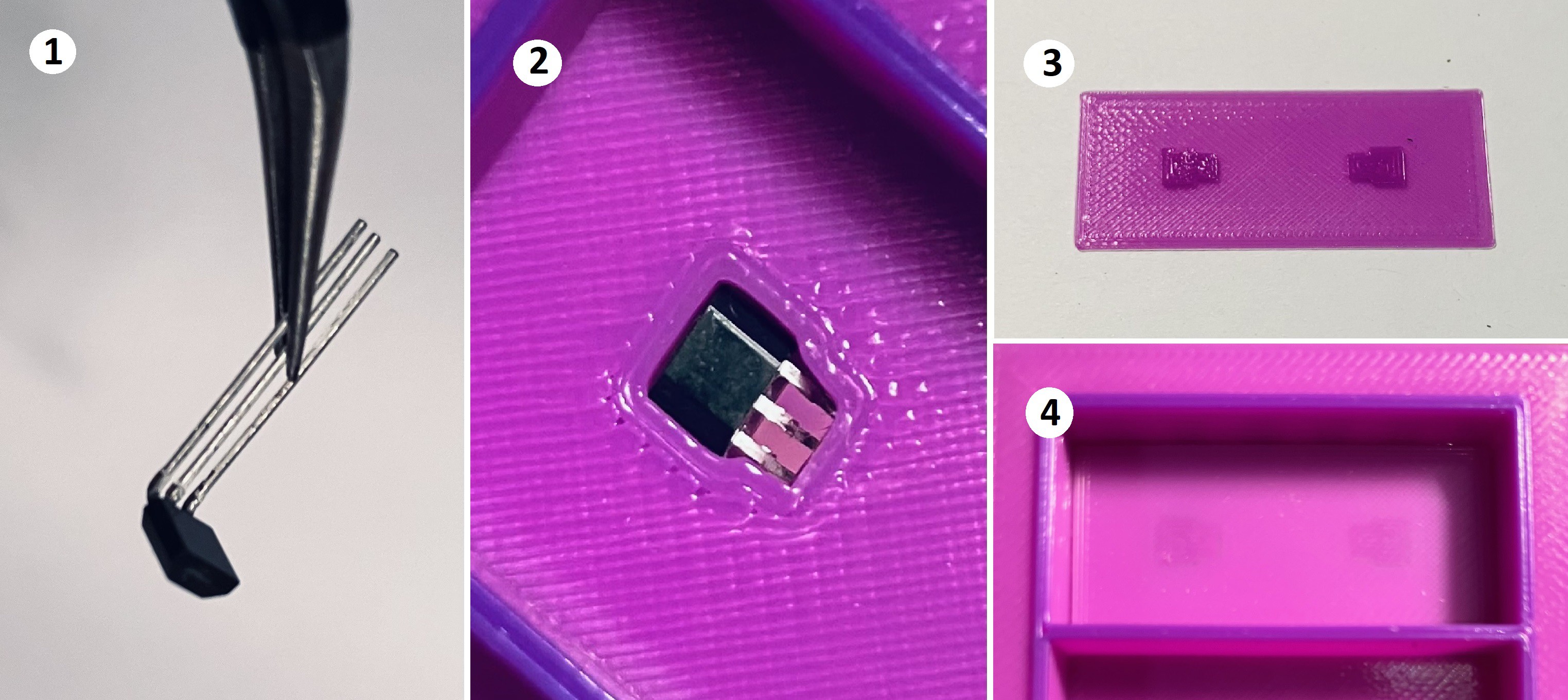
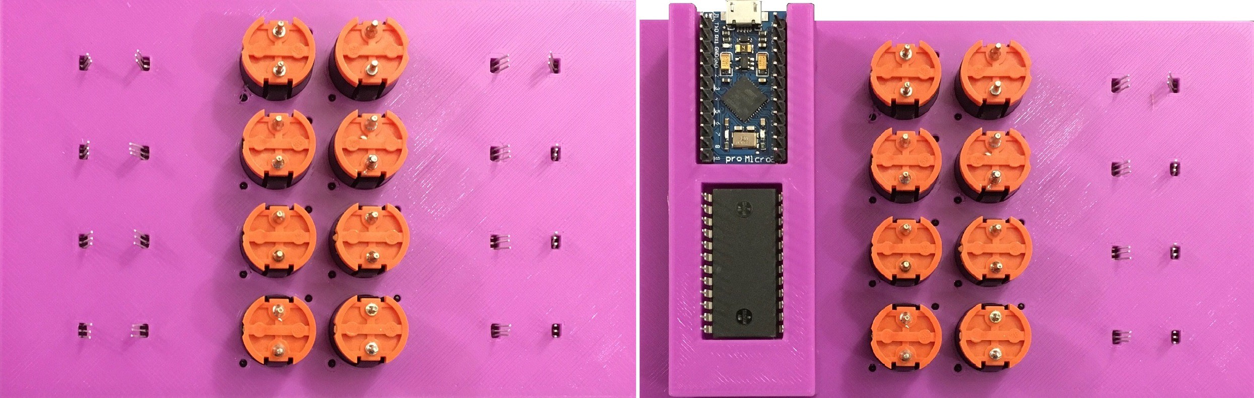
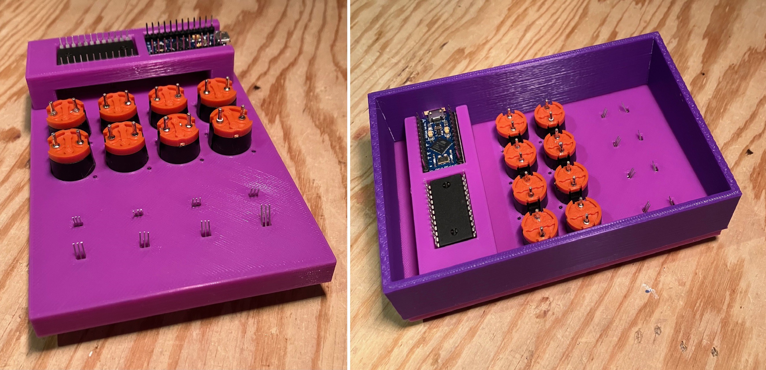
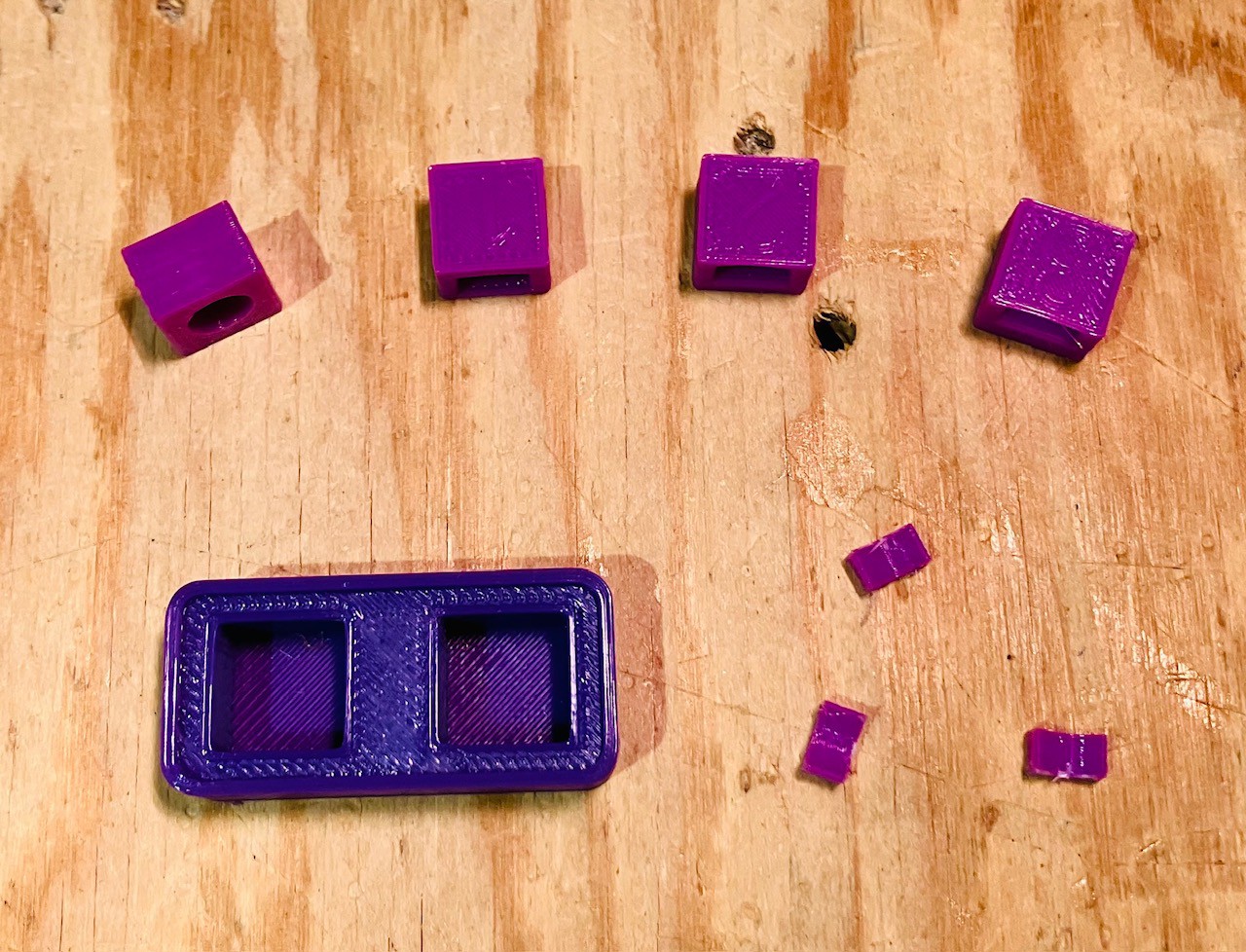
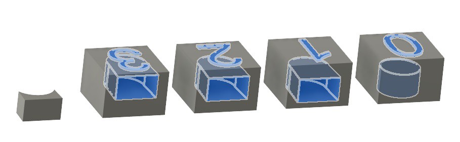
My MacroPad has eight keys based on nice Fubata MD-4PCS switches. Beside each key is a slot that can hold a "special" tile which identifies a macro to be associated with that key. To be perfectly clear, all of the available macros will be defined in the firmware in much the same way as with other MacroPads. The tile holds a "simple numeric value" that maps the associated key to a specific internally defined macro sequence when the tile is inserted into the slot (details to follow).
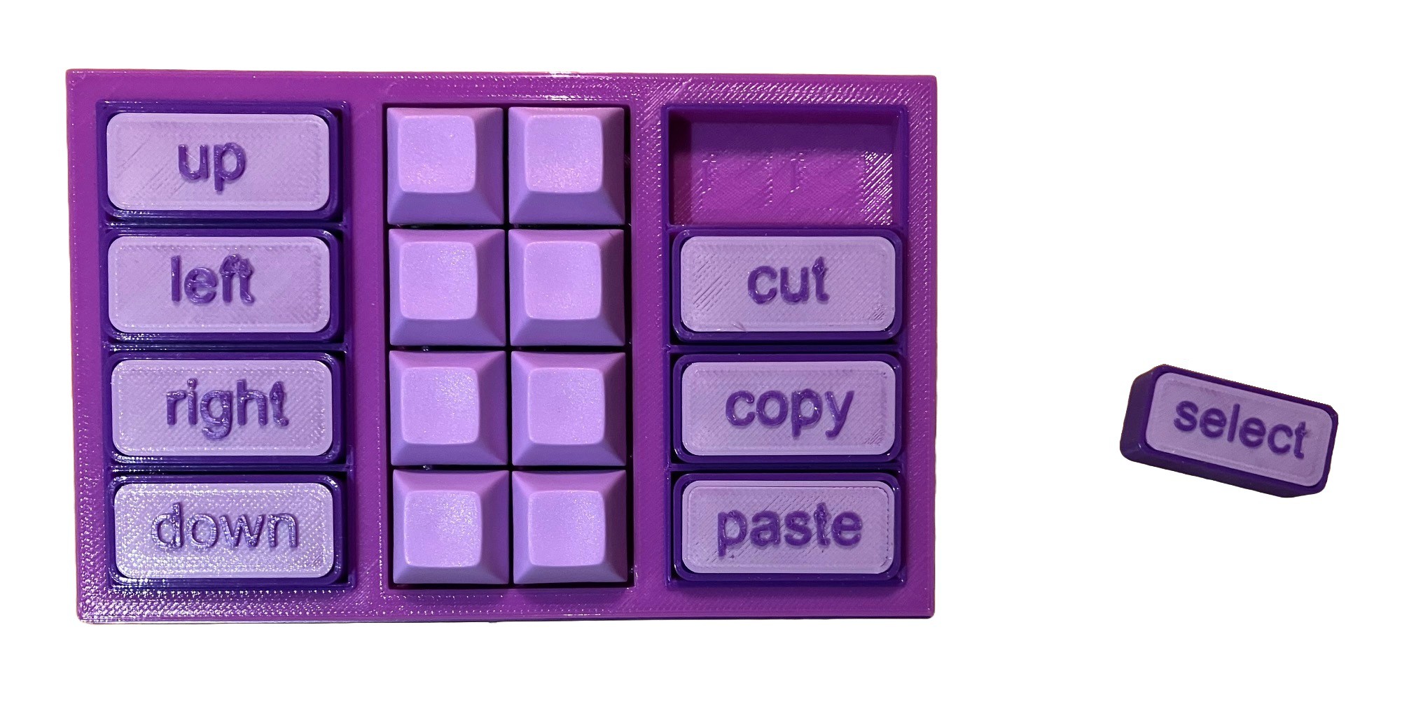
Tiles can be swapped at any time changing the key's macro immediately. I'm a big fan of this tactile based interface.
It's pretty obvious how this solves the few keys many macros problem. The user can define a large number of macros (I think up to 64 at this point) internally and can activate any eight macros at a time by simply slotting in the appropriate tiles.
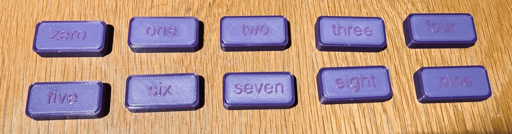
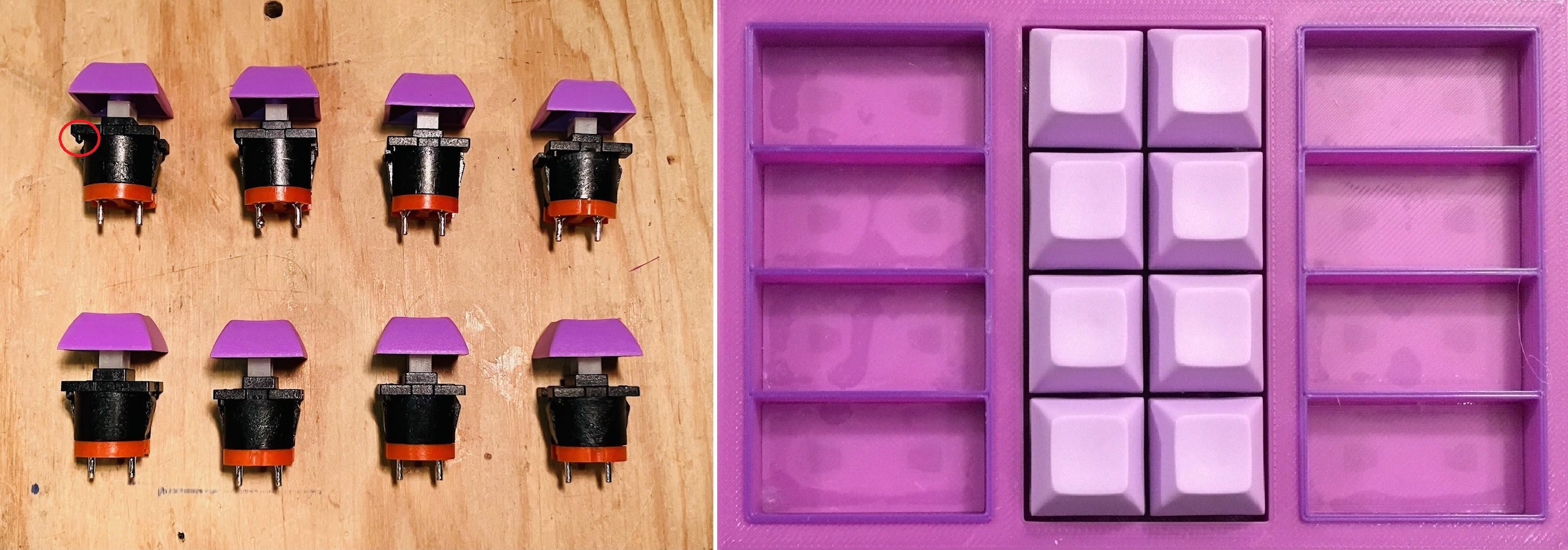
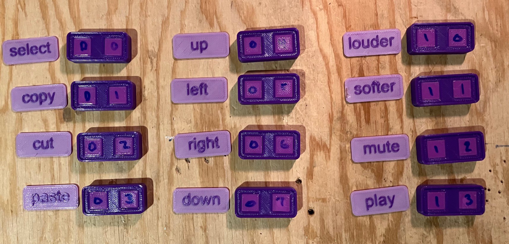
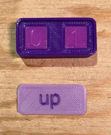
Furthermore the tile's approximately 2U size (necessary for technical reasons) is a great surface for defining meaningful, easy to understand, labels for the macro's action. Of course if you are attached to cool but cryptic icons you can do that too.
If there is any downside, it's that the tiles do take up a...
Read more »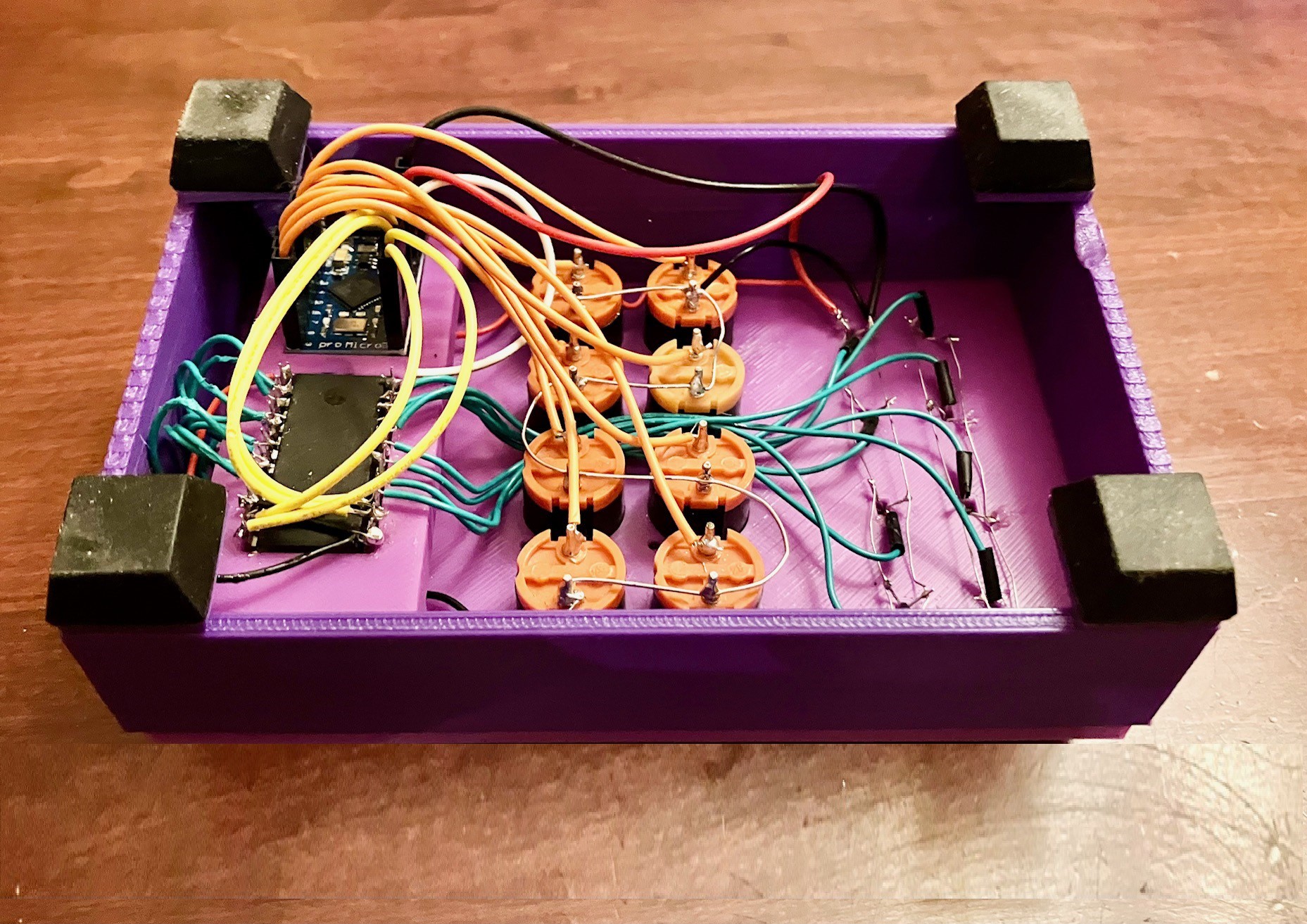


 bobricius
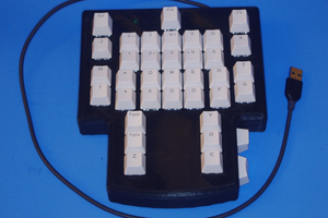

 Awesome Makes
 Keith Violette
Cool idea. You should easily be able to get 100s (?) of unique resistances and would only require one analog read per tile not two.