 Silícios Lab
In the last few weeks we started developing this robotic arm. It is made up of 5 servomotors. To facilitate its development, it was necessary to create a control center to connect and control all servomotors.

In this application we decided to develop the project of an electronic board to receive power from the circuit, power and control all the project's servomotors.
In this article we will discuss the functioning of the board's electronic circuit and show all its features so that it can be applied in numerous robotics projects.Below you can see the 3D image of our printed circuit board.

Therefore, at the end of this article you will learn the following points below:
- How the electronic circuit structure of the USB-C Port works,
- How the USB-SERIAL converter circuit works with the CH340G CHIP,
- +5V Voltage Regulator Circuit, and
- ATMEGA328P CHIP configuration circuit.
Now, let's understand each part of the electronic circuit.
Project Electronic Circuit
Below we have the complete electronic schematic for this project.


Next, we will begin the presentation of the USB-C connector circuit block and voltage regulator circuit.
USB-C circuit and voltage regulator
Using circuits with USB Type-C connectors offers several advantages over older USB connectors such as USB-A and USB-B. Here are some of the most significant advantages:
- The USB-C connector is symmetrical, which means it can be inserted in any direction, making it much more convenient compared to USB-A and USB-B connectors that have a specific orientation. This eliminates the frustration of trying to connect the cable correctly.
- Higher data transfer rate: USB-C supports faster data transfer speeds than its predecessors. It can support transfer rates of up to 10 Gbps (USB 3.1 Gen 2), which is twice as fast as USB 3.0 (USB-A).
- Higher power capacity: USB-C supports higher power than previous USB connectors. This allows you to charge devices faster and provide power to more power-hungry devices like laptops, monitors, and even some virtual reality devices.
- Universal compatibility: USB-C is becoming a widely accepted standard in electronic devices such as smartphones, tablets, laptops, desktops, accessories and peripherals. This means you can use the same cable to connect a variety of devices, reducing clutter and the need to carry multiple types of cables.
- Compact Dimensions: USB-C connectors are small and compact, making them ideal for thin and light devices. This helps in creating more elegant device designs.
- Durability: USB-C connectors are designed to withstand a significant number of plugging and unplugging cycles, making them more durable than some older connectors.
Based on these various advantages mentioned, we used a USB - C connection circuit made available by PCBWay and assembled the circuit below.
See the electronic schematic below and observe the USB-C port connection diagram.

In the electronic design of the printed circuit board, this circuit has two functionalities:
- Allow the transfer of code from the computer to the Microcontroller;
- Power supply to the electronic board via the USB-C port, but be aware that the USB-C port is not used to supply current and voltage to the servomotors connected to the PWM pins. The motors are powered via the 7.4V battery connector.
Circuit board electronic power supply
There are two ways to power the circuit board. You can power it via the USB-C port and the 7.4V Li-Ion battery connector. USB-C is a circuit that allows us to power the CHIP with a maximum input voltage of +5V. The main function of the USB-C port is to transfer code from the computer to the ATMEGA328P Microcontroller.
In this project, a power supply selector circuit was inserted, if the project is powered by batteries and the USB-C port at the same time. In this case, the circuit selects batteries as the main power source to power the project. If the battery is not connected, the main source will be the USB-C port.
The...
Read more »
 Saimon
 George
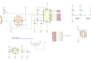
 Zoltan Gyarmati