In this revision of the PCB, I'm using a Seed XIAO RP2040, which is based on the RP2040. It's supported by CircuitPython which offers lots of useful libraries, but not one for the TDC chip I'm using. Generally I would say CircuitPython is pretty good for development, but does seem to have some stability issues when run for long periods of time. However, just dropping the code on a USB drive is pretty nice.
We are using the Time of Flight chip TDC7200 to measure the time between when we send a pulse and when we see the final reflection from the other end of the line. So the general flow is to setup everything by configuring the TDC and clock generation chip (a Si5351). Then trigger a measurement and read the result back.
The TDC is accessed over SPI and data is read or written into registers. So all the configuration looks like writing values to address with various bits set that indicate how the chip should be configured.
def config_tdc():
    calibration_periods = 1 # 1 = 10 periods
    calibration_shift = 6
    avg_cycles = 0b111 # 128 cycles
    avg_cycles_shift = 3
    reg_value = (calibration_periods << calibration_shift) | (avg_cycles << avg_cycles_shift)
    write_register(CONFIG2_ADDR, reg_value)
Everything is set as the default except we can enable taking multiple measurements and averaging it together on the TDC before returning the result. This ends up being much faster than doing the equivalent number of single measurements and doing the averaging on the RP2040 because it takes more time to do all the SPI interactions then it takes to do another measurement.
Another thing we need to setup is receiving the signal from the TDC to send a pulse. There are many different ways to do this, but since we want to do this quickly to minimize the time between measurements, I used a simple PIO program to just wait for a signal and then send the pulse to the Schmitt trigger.
# This will trigger a pulse whenever the TDC requests it
trigger_pio = '''
.program trigger
    wait 1 pin 0    ; wait for trigger pin to be set
    set pins, 1     ; send pulse
    set pins, 0
    ; loop back to the beginning
'''
triggered_asm = adafruit_pioasm.assemble(trigger_pio)
sm = rp2pio.StateMachine(triggered_asm,
                        frequency=10000,
                        first_set_pin=start_pin,
                        first_in_pin=trigger_pin)
The reason I didn't just set the output of the TDC directly to the Schmitt Trigger is that there is a minimum delay between the TDC requesting a start pulse and the pulse actually happening. The easiest way to add a delay is to have the RP2040 do it and then it can be adjustable too. Turns out that the no extra delay was needed.
So now we can actually do a measurement:
def do_measurement():
    "Time of flight in nanoseconds"
    start_measure = 0b1 # start measurement mode 1
    write_register(CONFIG1_ADDR, start_measure)

    # Wait for a measurement to be ready
    while done.value:
        pass

    time1 = read_register(TIME1_ADDR, reg_size=3) & TIME_MASK
    cal1 = read_register(CAL1_ADDR, reg_size=3) & CAL_MASK
    cal2 = read_register(CAL2_ADDR, reg_size=3) & CAL_MASK

    tof = calc_tof_mode1(clock, time1, cal1, cal2)
    # print("TOF = %s" % (tof*10**9))
    return tof * 10**9
Setting the start measure bit in the CONFIG1 register will cause the TDC to send the start signal back to the RP2040, which via the PIO program will send a pulse to the Schmitt trigger, which will then send the pulse, and the START pin of the TDC. Once that pulse reflection crosses the comparator level, a edge will be sent to STOP pin of the TDC.
This happens 128 times and when that is done, the done pin will be brought low, which indicates the RP2040 should read the result. Three values are read and then we can calculate the actual value
def calc_tof_mode1(clock, time, cal1, cal2):
    if time == 0 or cal1 == 0 or cal2 == 0:
        return -1
    freq = clock.clock_0.frequency
    period = 1/freq
    calCount = (cal2 - cal1)/9 # using default cal periods of 10
    if calCount == 0:
        return -1
    normLSB = period / calCount
    return time * normLSB
This is pulled right from the TDC datasheet.
I actually do even more averaging on the RP2040 since there is a fair amount of jitter in the measurements. It's just a simple sliding window based on the median of the measurements to better reject outliers.
samples = []
next_samp = 0
window_size = 50
samp_min = 8
samp_max = 50
def add_sample(new_samp):
    if new_samp > samp_max or new_samp < samp_min:
        return -1
    global next_samp
    if next_samp < len(samples):
        samples[next_samp] = new_samp
    else:
        samples.append(new_samp)
    next_samp = (next_samp + 1) % window_size

    return median(samples)

def median(lst):
    n = len(lst)
    s = sorted(lst)
    return (s[n//2-1]/2.0+s[n//2]/2.0, s[n//2])[n % 2] if n else None
Most of these outliers came from problems getting corrupted data over SPI.
SPI Issues
One of the weird issues I ran into was the SPI transfer would return garbage data sometimes. It took a while to track down what was happening, but it seemed to be related to the SPI clock speed. When I set the clock speed for the SPI bus:
def open_spi():
while not spi.try_lock():
pass
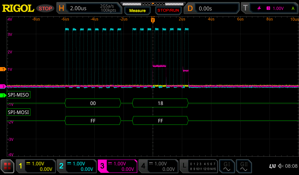
spi.configure(baudrate=2000000, phase=0, polarity=0)The TDC could not operate at anywhere near it's advertised 20MHz. I originally suspected some kind of signal integrity issue, but after looking at the glitches I don't think so. Even when it "works" the MISO signal is very weak.
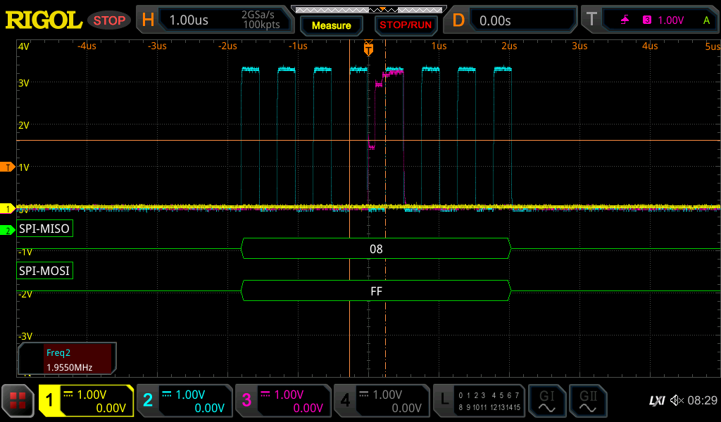
But sometimes it does manage to get to the normal voltage level
And if we increase the clock past 2MHz this gets even worse
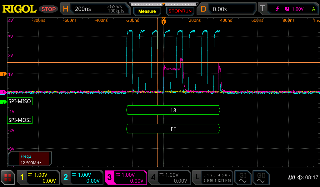
At the point the RP no longer can actually read the data even if the scope can still decode it.
So we just limit to lower speeds than the datasheet says it should be able to handle. I'm still suspicious I'm doing something wrong, but I have no idea what it is and going slow seems to clear up the problem.
That's the general gist of the code. I'll include the full code for this revision in case it helps anyone else out.
Full code
import board
import busio
import adafruit_si5351
import adafruit_pioasm
import rp2pio
import board
import busio
import board
import digitalio
import pwmio

enable = digitalio.DigitalInOut(board.D2)
enable.direction = digitalio.Direction.OUTPUT
enable.value = False

start_pin = board.D0

trigger_pin = board.D1

out_pin = board.D6
pwm_out = pwmio.PWMOut(out_pin, frequency=5000000)

done = digitalio.DigitalInOut(board.D3)
done.direction = digitalio.Direction.INPUT
done.pull = digitalio.Pull.UP

cs = digitalio.DigitalInOut(board.D7)
cs.direction = digitalio.Direction.OUTPUT
cs.value = True
spi = busio.SPI(board.SCK, MISO=board.MISO, MOSI=board.MOSI)

def open_spi():
    while not spi.try_lock():
        pass
    spi.configure(baudrate=2000000, phase=0, polarity=0)

CONFIG1_ADDR = 0
CONFIG2_ADDR = 1
INT_STATUS_ADDR = 2
INT_MASK_ADDR = 3
TIME1_ADDR = 0x10
CLOCK1_ADDR = 0x11
TIME2_ADDR = 0x12
CLOCK2_ADDR = 0x13
CAL1_ADDR = 0x1B
CAL2_ADDR = 0x1C

CAL_MASK = (1 << 23) - 1
TIME_MASK = (1 << 23) - 1
COUNT_MASK = (1 << 16) - 1

AUTO_INC_MASK = 0b10000000
RW_BIT = 0b01000000
REG_MASK = 0b0011111

def read_register(reg_addr, reg_size=1):
    result = bytearray(reg_size + 1)

    control = reg_addr & REG_MASK
    open_spi()
    try:
        cs.value = False
        spi.write_readinto(out_buffer=bytes([control] + [0] * reg_size), in_buffer=result)
    finally:
        cs.value = True
        spi.unlock()
    return int.from_bytes(result[1:], 'big', False)

def write_register(reg_addr, data):
    control_data = reg_addr & REG_MASK
    control_data |= RW_BIT
    open_spi()
    try:
        cs.value = False
        spi.write(bytes([control_data, data]))
    finally:
        cs.value = True
        spi.unlock()
    return


def config_si5351():
    i2c = busio.I2C(board.SCL, board.SDA)
    si = adafruit_si5351.SI5351(i2c)
    si.pll_a.configure_integer(30)
    si.clock_0.configure_integer(si.pll_a, 50)
    si.outputs_enabled = True
    print('Clock 0: {0:0.3f} MHz'.format(si.clock_0.frequency/1000000))
    return si

clock = config_si5351()

def calc_tof_mode2(clock, time1, time2, count, cal1, cal2):
    freq = clock.clock_0.frequency
    period = 1/freq
    calCount = cal2 - cal1 # using default cal periods of 2
    normLSB = period / calCount
    TOF = normLSB * (time1 - time2) + count * period
    return TOF

def calc_tof_mode1(clock, time, cal1, cal2):
    if time == 0 or cal1 == 0 or cal2 == 0:
        return -1
    freq = clock.clock_0.frequency
    period = 1/freq
    calCount = (cal2 - cal1)/9 # using default cal periods of 10
    if calCount == 0:
        return -1
    normLSB = period / calCount
    return time * normLSB

samples = []
next_samp = 0
window_size = 50
samp_min = 8
samp_max = 50
def add_sample(new_samp):
    if new_samp > samp_max or new_samp < samp_min:
        return -1
    global next_samp
    if next_samp < len(samples):
        samples[next_samp] = new_samp
    else:
        samples.append(new_samp)
    next_samp = (next_samp + 1) % window_size

    return median(samples)

def median(lst):
    n = len(lst)
    s = sorted(lst)
    return (s[n//2-1]/2.0+s[n//2]/2.0, s[n//2])[n % 2] if n else None

# This will trigger a pulse whenever the TDC requests it
trigger_pio = '''
.program trigger
    wait 1 pin 0    ; wait for trigger pin to be set
    set pins, 1     ; send pulse
    set pins, 0
    ; loop back to the beginning
'''
triggered_asm = adafruit_pioasm.assemble(trigger_pio)
sm = rp2pio.StateMachine(triggered_asm,
                        frequency=10000,
                        first_set_pin=start_pin,
                        first_in_pin=trigger_pin)


def config_tdc():
    calibration_periods = 1 # 1 = 10 periods
    calibration_shift = 6
    avg_cycles = 0b111 # 128 cycles
    avg_cycles_shift = 3
    reg_value = (calibration_periods << calibration_shift) | (avg_cycles << avg_cycles_shift)
    write_register(CONFIG2_ADDR, reg_value)

def do_measurement():
    "Time of flight in nanoseconds"
    # config_reg = read_register(CONFIG2_ADDR)
    # print("config2 = " + hex(config_reg))

    # print("trigger: %s" % trigger.value)

    # start_measure = 0b11 # start measurement mode 2
    start_measure = 0b1 # start measurement mode 1
    write_register(CONFIG1_ADDR, start_measure)

    # config_reg = read_register(CONFIG1_ADDR)
    # print(hex(config_reg))

    # status_reg = read_register(INT_STATUS_ADDR)
    # print(hex(status_reg))

    # stop.value = True
    # stop.value = False

    # status_reg = read_register(INT_STATUS_ADDR)
    # print(hex(status_reg))

    # config_reg = read_register(CONFIG1_ADDR)
    # print(hex(config_reg))
    # cal1 = read_register(CAL1_ADDR, reg_size=3)
    # print(hex(cal1))
    # cal2 = read_register(CAL2_ADDR, reg_size=3)
    # print(hex(cal2))

    # if status & 1:

    # Wait for a measurement to be ready
    while done.value:
        pass
        # print("+", end="")
    # print("")

    # status = read_register(INT_STATUS_ADDR)
    # print("STATUS = %s" % hex(status))

    # while not (status & 0b10000):
    #     status = read_register(INT_STATUS_ADDR)
    #     print("STATUS = %s" % hex(status))

    time1 = read_register(TIME1_ADDR, reg_size=3) & TIME_MASK
    # print("TIME1 = %s " % hex(time1))
    # time2 = read_register(TIME2_ADDR, reg_size=3) & TIME_MASK
    # print("TIME2 = %s" % hex(time2))
    # count = read_register(CLOCK1_ADDR, reg_size=3) & COUNT_MASK
    # print("CLOCK1 = %s" % hex(count))
    cal1 = read_register(CAL1_ADDR, reg_size=3) & CAL_MASK
    # print("CAL1 = %s" % hex(cal1))
    cal2 = read_register(CAL2_ADDR, reg_size=3) & CAL_MASK
    # print("CAL2 = %s" % hex(cal2))
    tof = calc_tof_mode1(clock, time1, cal1, cal2)
    # print("TOF = %s" % (tof*10**9))
    return tof * 10**9

def main():
    enable.value = True
    config_tdc()

    counter = 0
    while True:
        avg = add_sample(do_measurement())
        if avg == -1:
            print("-", end="")
            continue
        counter = (counter + 1) % window_size
        if counter == 0:
            print("\nTOF = %s" % (avg))
            set_output(avg)
        else:
            print(".", end="")

if __name__ == "__main__":
    main()
Discussions
Become a Hackaday.io Member
Create an account to leave a comment. Already have an account? Log In.