As I was trying to put together a simple automated plant watering solution, I figured that having the amount of water be driven by a soil sensor would be a good idea. So I tried the default cheap capacitive moisture sensors, but had several of them fail on me after only a few weeks. While looking for better solution I ran over a different technique call Time Domain Reflectometry that could be used to make that measurement. How hard could it be to make one of those?

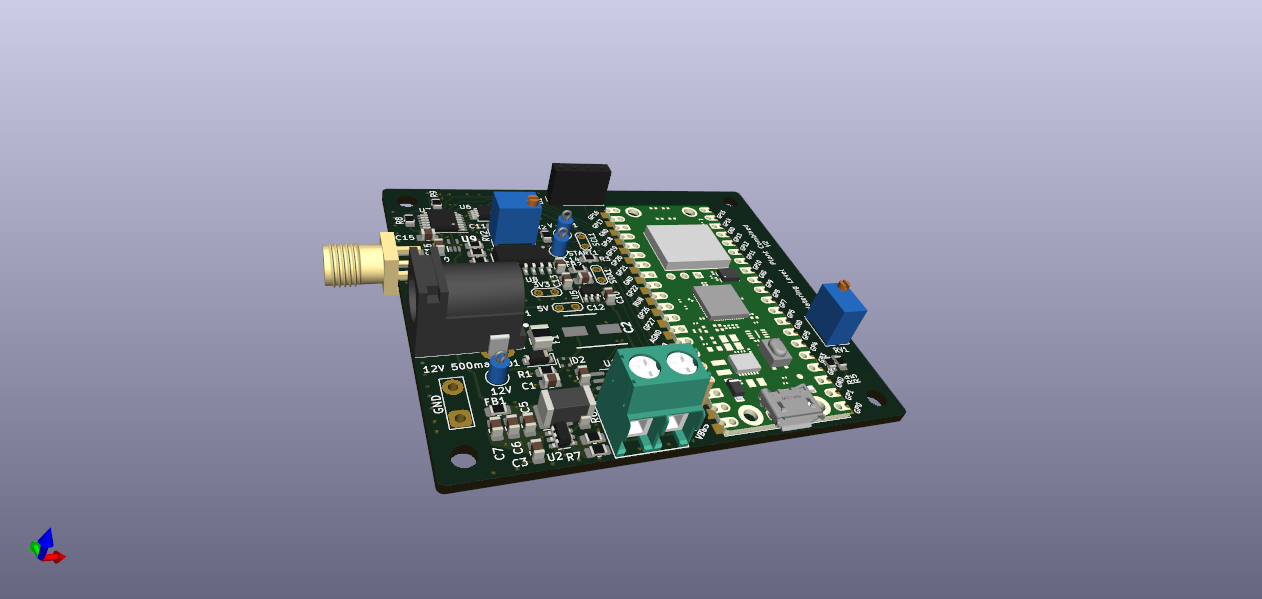
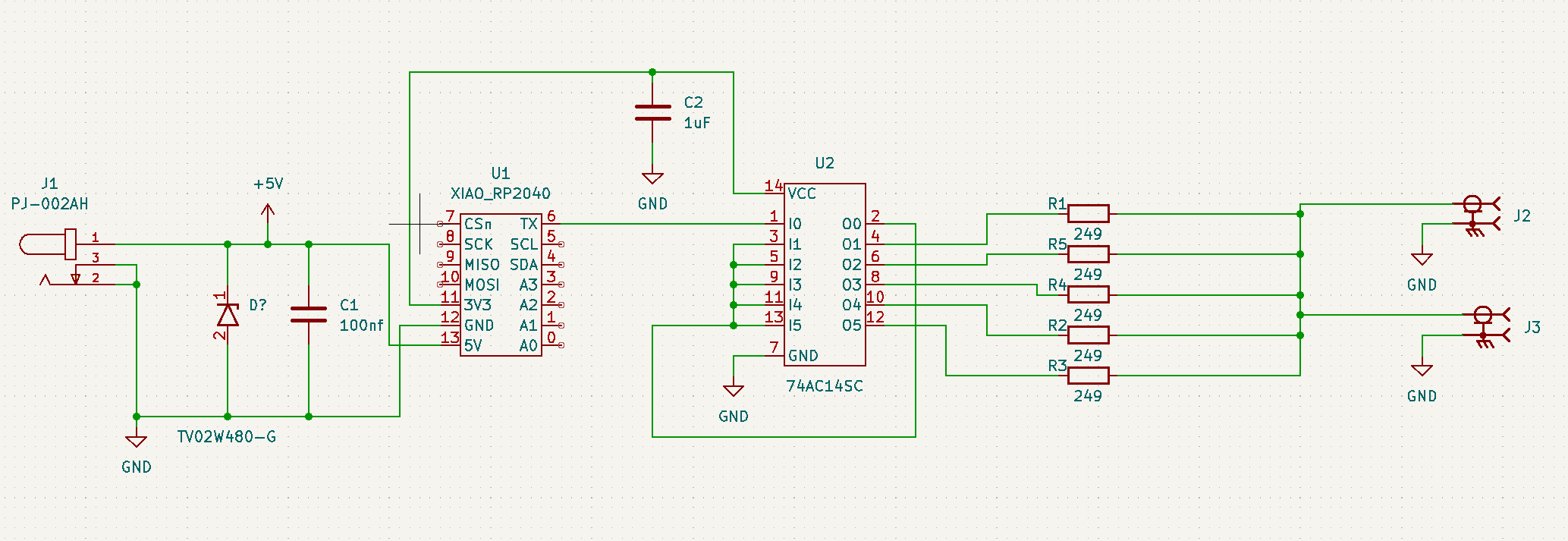
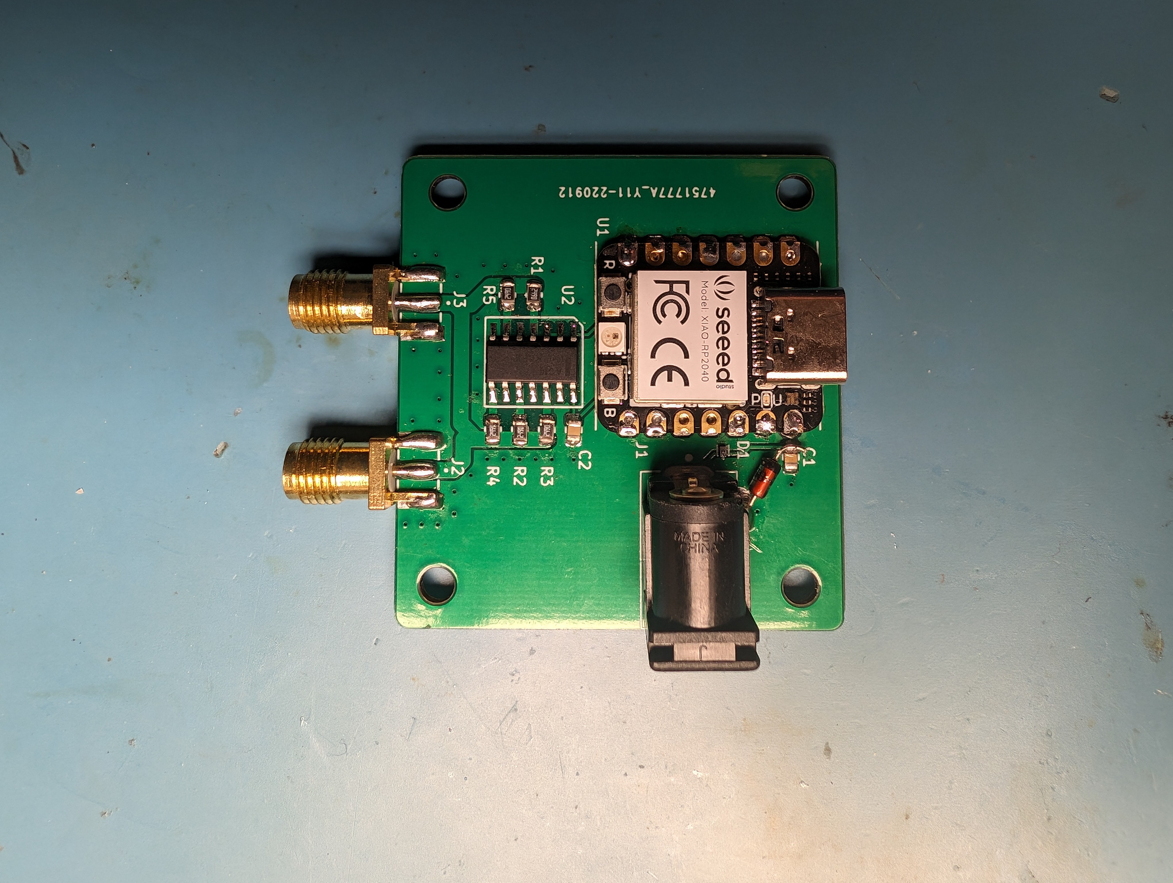
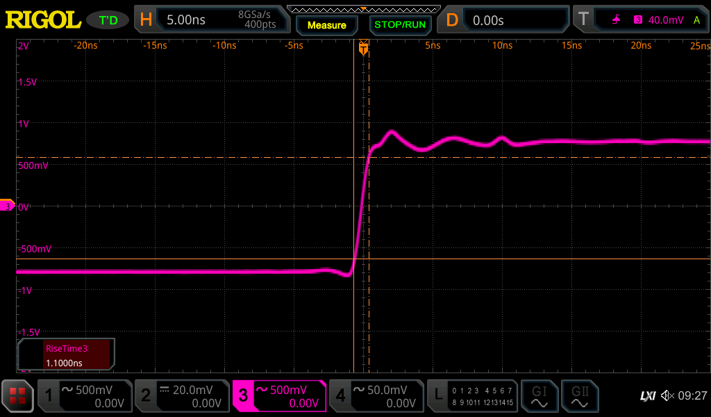
Many hours of debugging, a few failed designs later and I have a working prototype based on a Time of Flight sensor and a Raspberry Pi Pico W that can log to a central server.
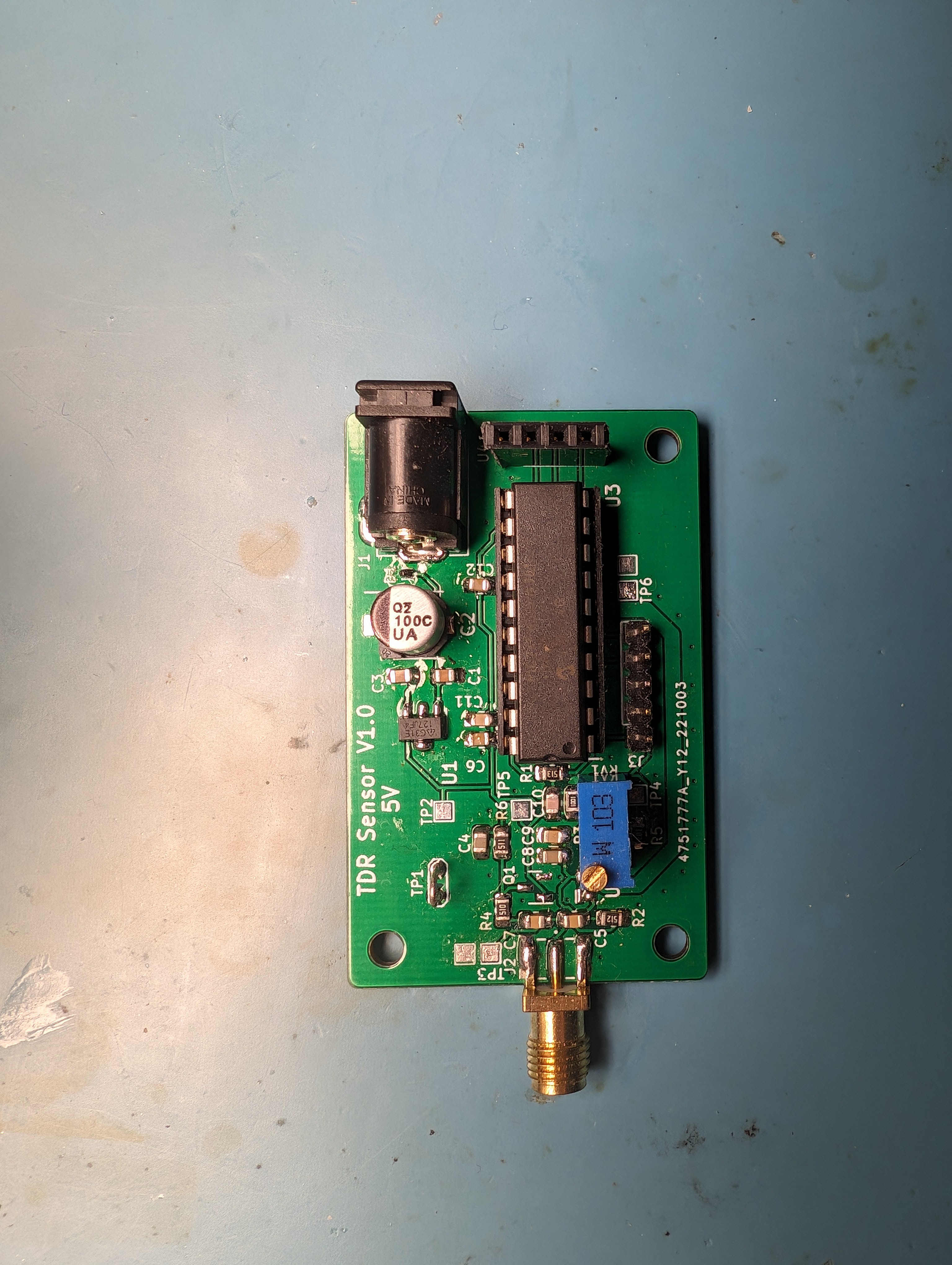
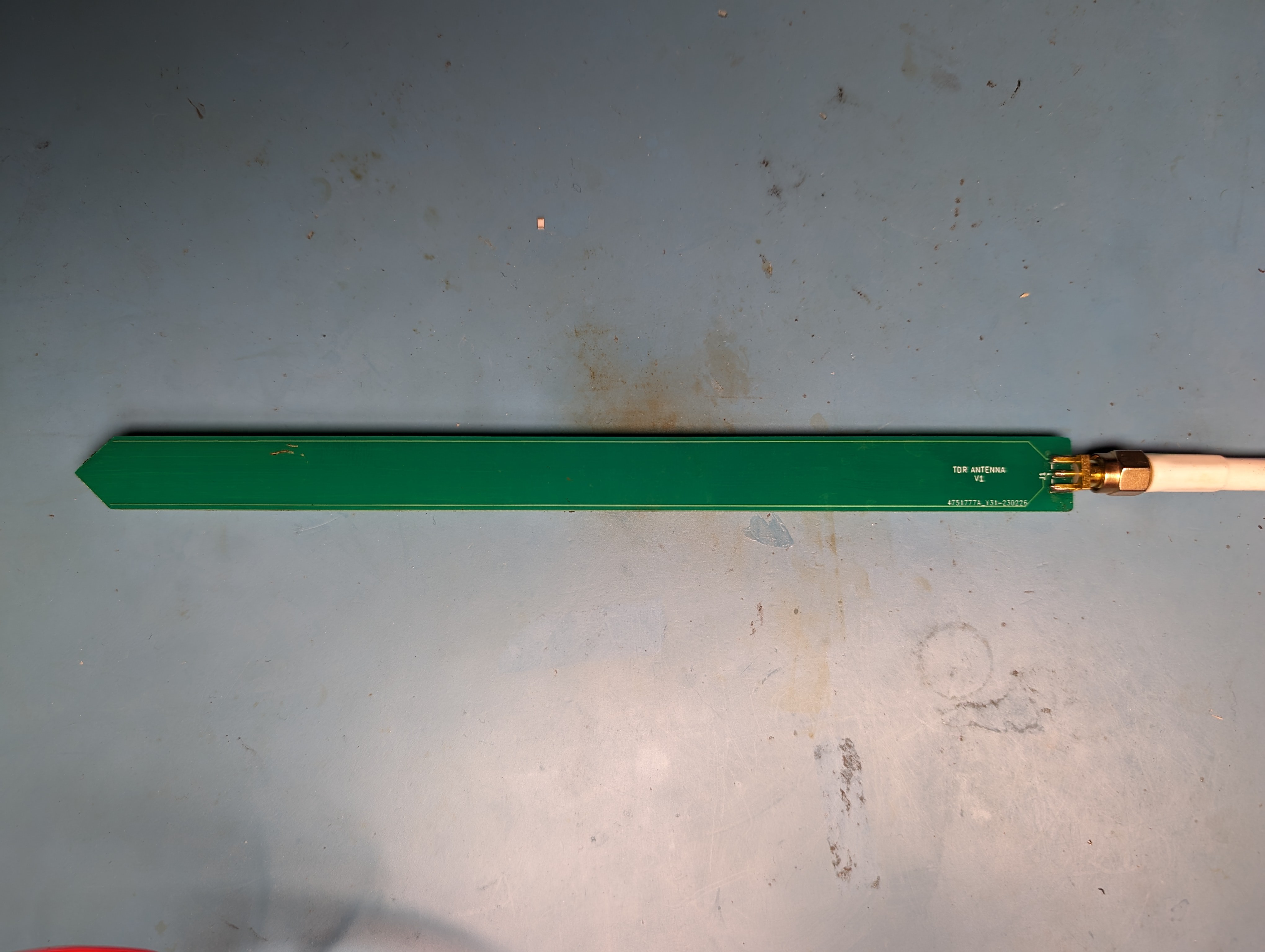
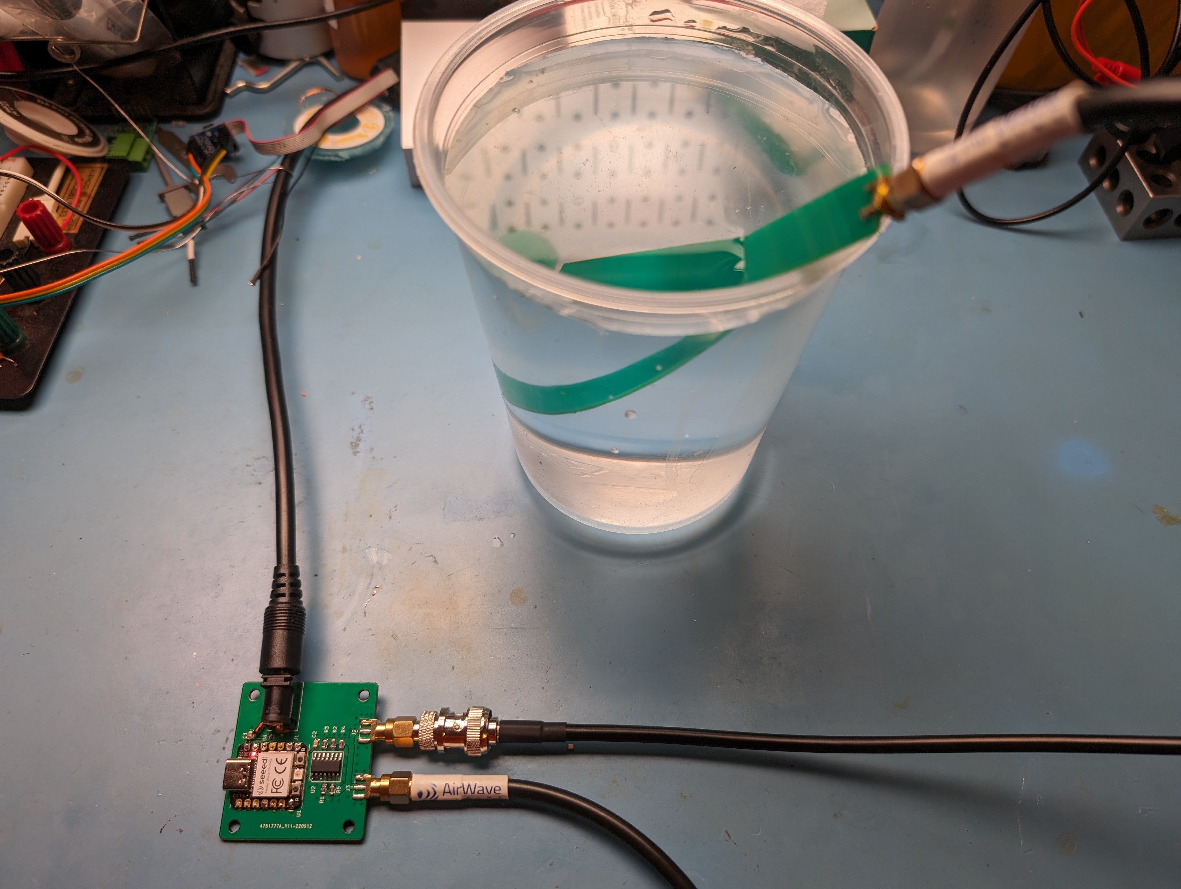
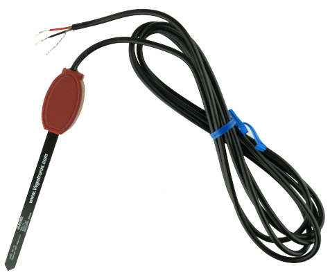
Using a PCB sensor that is inserted in to the soil of a plant, it is able to see the change in moisture content in the soil over time. It's sensitive enough that it can see the change in moisture over a single day. This allowed me to set a level that triggers watering and have small amount of water dispensed with a pump to keep the moisture level fairly consistent.
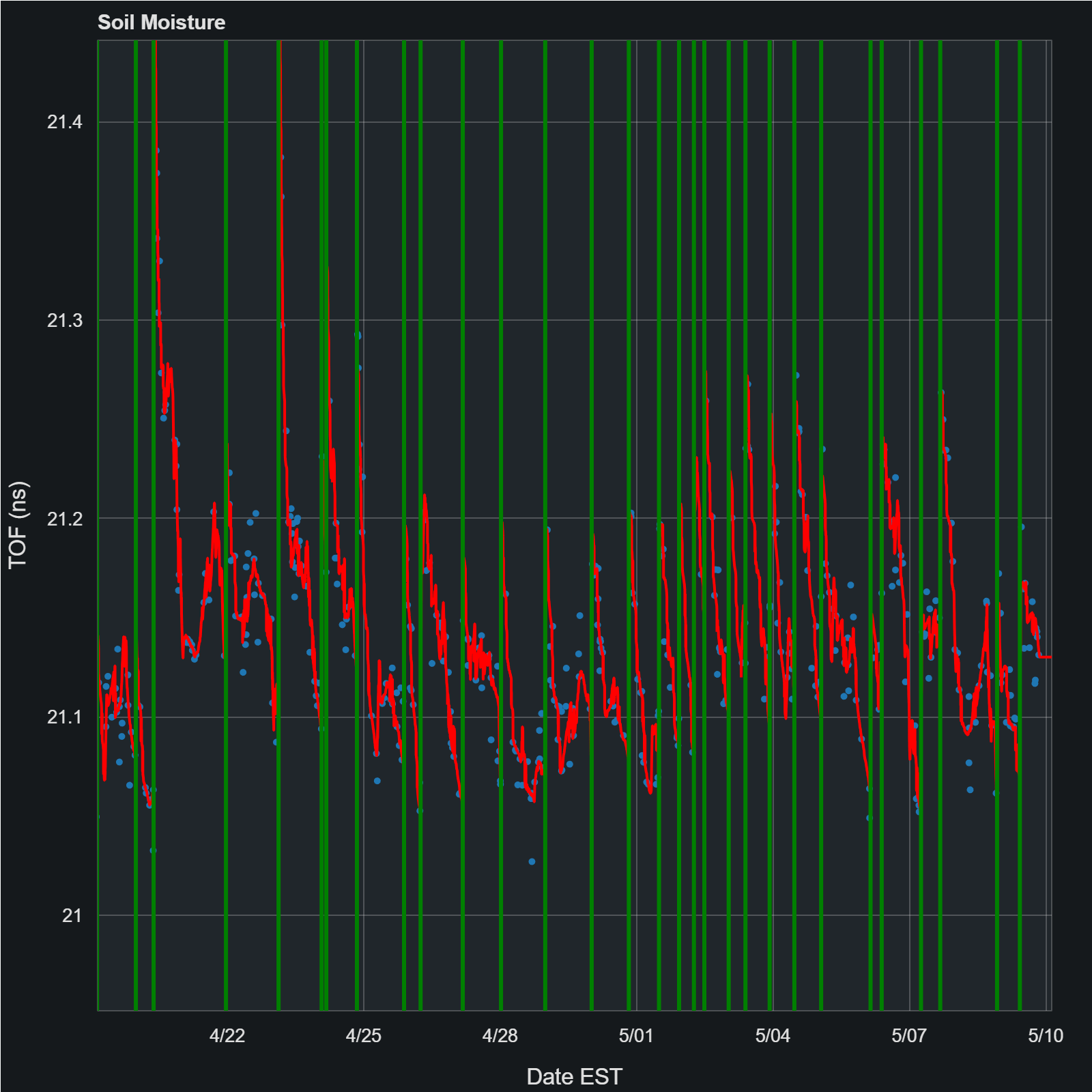
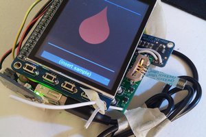
This is a sensor log of a plant. The green vertical lines are when watering was triggered and the red line is the average detected moisture level. Each dose of water is pretty small, but shows up as a huge spice of moisture that then drops quickly as it spreads more evenly thru the plant pot.
The test plant isn't dead after a few months, so by at least that metric, the project has achieved it's goal. However, there are still some things that need to be done:
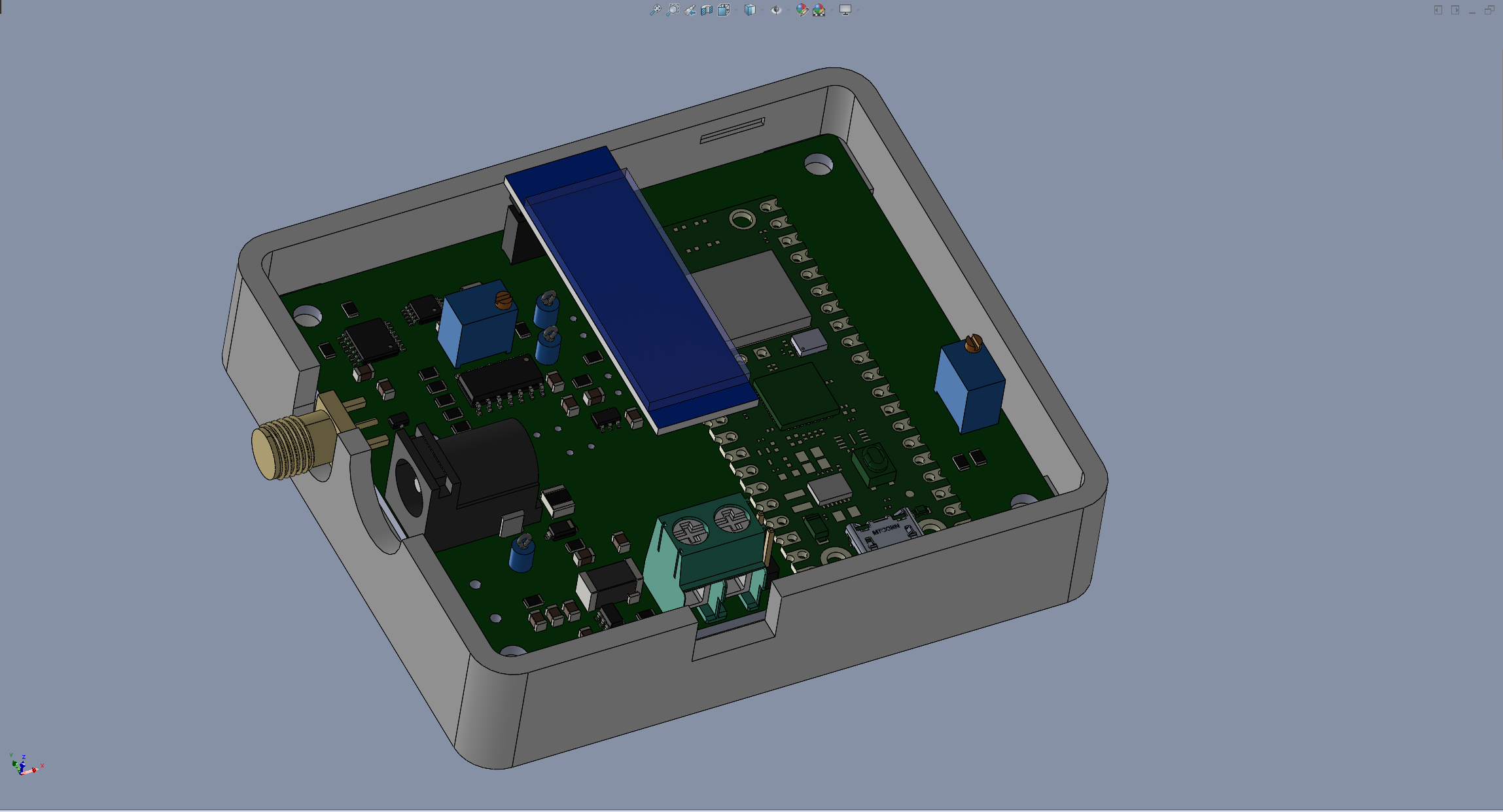
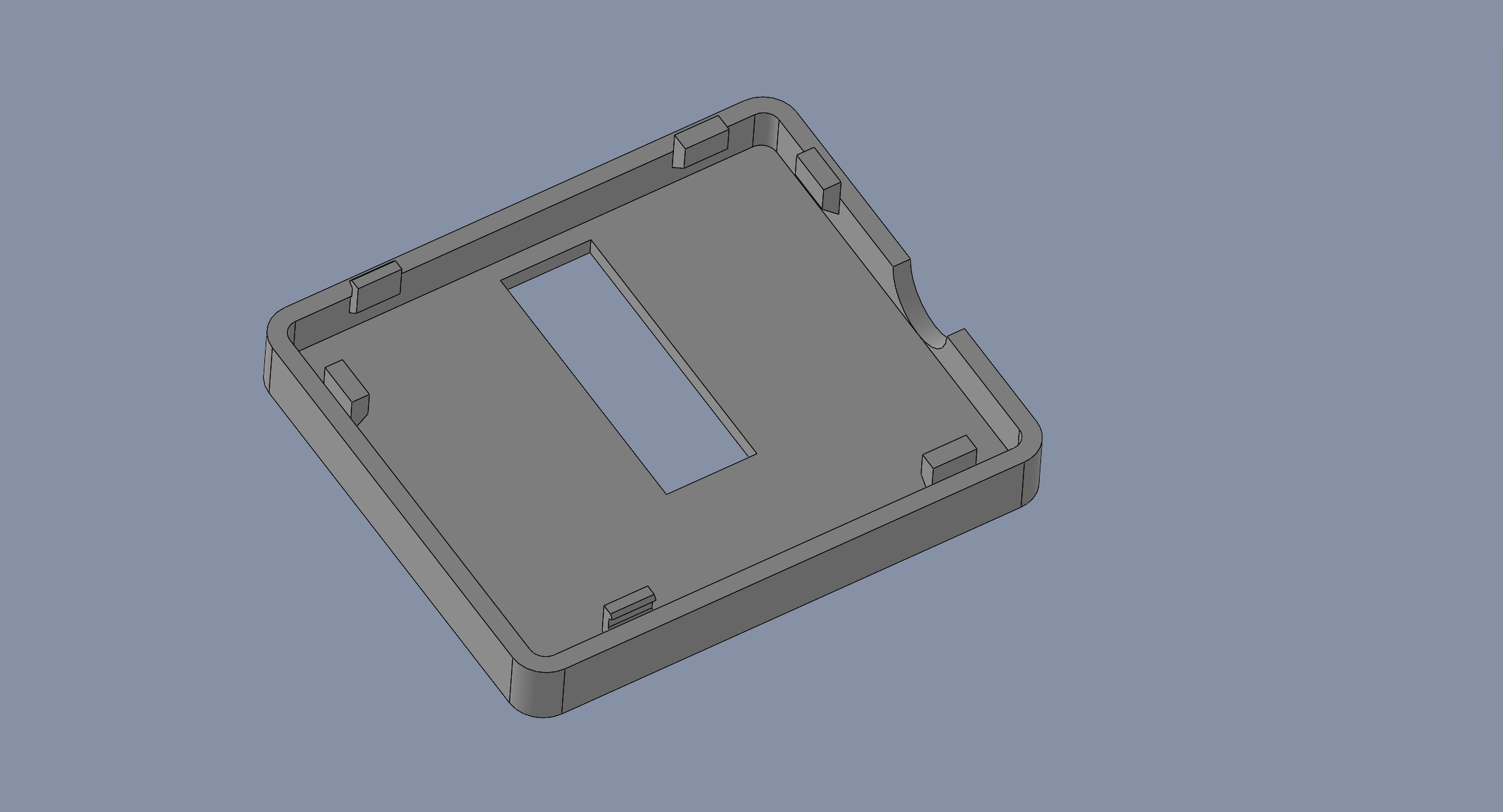
- Design/create an enclosure
- Finish rewrite to Rust
- Create single PCB with integrated antenna
I'm going back and writing build logs to document some of the steps I did, which is really more of the point of this whole process. But if you want to jump ahead and see some of the results the KiCad and RP2040 CircuitPython code can be found at: https://github.com/theblinkingman/plant-waterer


 Jonathan Buchanan
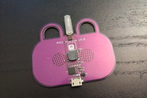
 deʃhipu
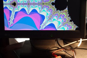
 Ted Yapo
 Eric Herbers
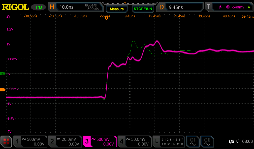
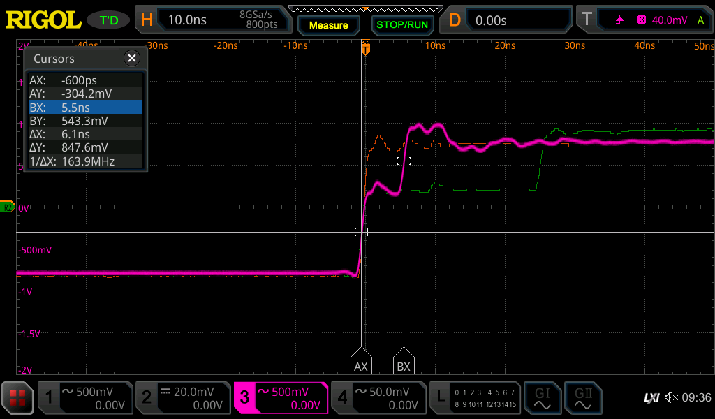
Not sure you are using a TDR method. You are measuring more capacitive values at a higher frequency. And for best results, you need to be above 10MHz as at those frequencies, the dielectric constant of the soil has less of an effect. I design commercial TDR probes and you need a pulse of <300ps rise-time. You need to send the pulse down a 15cm probe and measure the first reflection with at least 10ps of resolution using a delay line. So this requires special h/w like PECL (postive emitter coupled logic) to achieve those speeds. In the article cited in the comments, the method uses TDT which also yields good results, but does require very high frequency measurements. Good news is that I used a PyBoard and micropython to take the measurements.