Guido
GuidoOverview
After designing, getting the parts and building this project on October '23, I realized the strong similarites with https://hackaday.io/project/186842-mini-solar-system and, I guess, with many unpublished others.
However I published it here anyway because I think a few peculiarities deserve public interest.
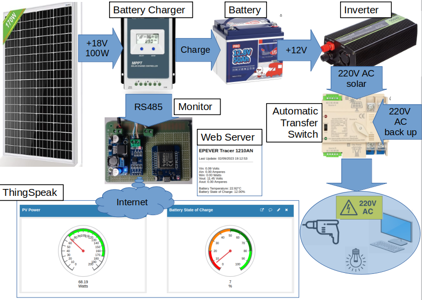
Block diagram
Solar Panel
i bought a nominal 170 W (111 x 77 cm) monocrystalline from Eco-Worthy. At the moment I cannot get more than 105W at noon with full sunshine in October at my 43° 11' Latitude. (I don't know why!).
Price: 85 Euros including shipping
Battery Charger
I bought an EPEVER MPTT 1210AN battery charger because I liked to monitor its working parameters by its RS485 output.
The Instructions say clearly to connect the Inverter to the battery (1) and not to the "user" dedicated output (2) without explaining why ☹️
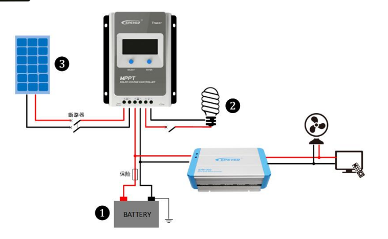
I suppose to have found the reason. EPEVER asks to connect the Inverter to the battery because the "user" output is capable of supplying a maximum of 20A, while an Inverter like the one I adopted could draw 50A (600 W) and more. However, this solution has an issue, at least for me, because my Inverter starts working (generating 220V) when the input voltage rise to 12.2V and stops when it falls below 10.8V. Such a range is too limited and well below the battery operating range, which is 11V to 13.5V. In fact the operating range of the EPEVER "user" output (i.e. when the "user" output is powered) is 11 - 13.5V.
Therefore I decided to add a 100A relay (like the ones for engine starters) powered by the "user" output. In this way I solve also another issue: the inverter draws around 1A when it has no load ☹️. This absorption leads the battery to discharge down to the limit when its BMS disconnects it and, as a consequence, during the night the battery is not operating and the monitor is not supplied.
The relay is driven by the Battery Voltage. See below the Voltage Hysteresis.
Price: 71 Euros including shipping
Voltage Hysteresis
This circuit connects the battery to the Inverter when the battery voltage rises above 13.5V and disconnects when it falls below 10.5V.
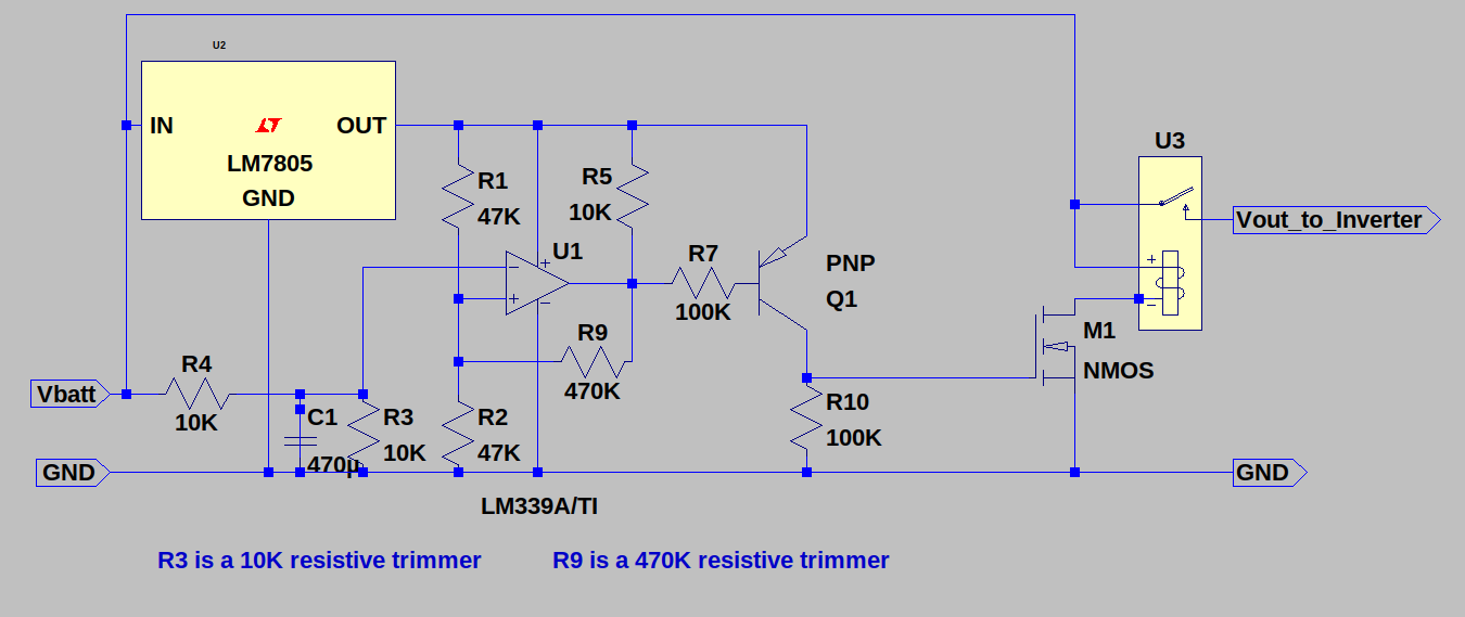
- Adjust R9 to obtain 3 Volts hysteresis (13.5 - 10.5 = 3V)
- Adjiust R3 to obtain max=13.5V min=10.5V
- (repeat if necessary)
Battery
I opted for a LiFePO4 12V 50Ah battery with internal BMS from TimeUSB.
Price: 155 Euros including shipping
Inverter
I found a Green Cell 500W pure sinusoidal inverter
The case remains pretty cool (<30° centigrade) while supplying 100-150 Watts, even if the noisy fan starts frequently. For this reason, I changed the original 12V 0.22A fan with a less noisy (and less powerful 😀) 12V 0.1A fan, scavenged from an old PC.
Price: 83 Euros including shipping
Automatic Transfer Switch
Until now, I didn't know the existence of such kind of device. The Jadeshay 2P 100A 220V I bought is nothing more than a very fast (less than 20 milliseconds) stepper relay but it is fast enough to switch almost seamlessly to the AC mains when the voltage from the inverter goes down and viceversa when the Inverter comes back to operate again. The supplied PC's I tested have no problem, while my 32" Samsung TV have a very short screen blanking (the screen becomes black and reappear in half a second).
I see two issues:
- the relay sounds a very noisy "clack", which I attenuated inserting the ATS in a 1.5 cm thick polistirene box.
- its electrical life is guaranteed for 2000 times (see Instructions) i.e. switching 6 times a day it should live less than an year ☹. I'll try to study a mosfet/TRIAC alternative or adopt a solution like this TRIAC based transfer switch.
Price: 35 Euros including shipping
Monitor
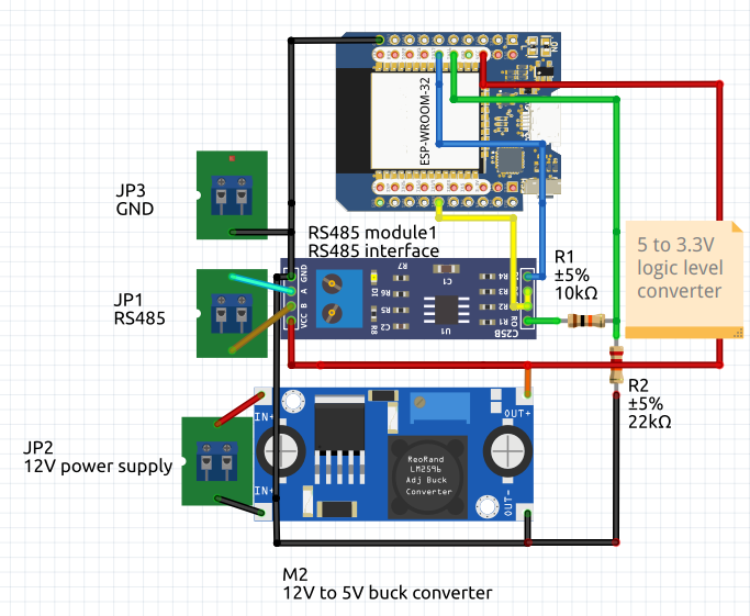
I built this circuit with an ESP32, an RS485 board and a 12V to 5V buck converter.
- Photovoltaic Voltage, Current and Power
- Battery Voltage
- Output Current (from the Battery Charger to the battery and Inverter).
- Battery Status of Charge
- Battery Temperature
See here an example of monitoring.
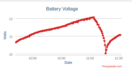
- Since the early morning of a cloudy day:
- the solar panel charges the battery quite slowly
- the AC mains supplies the appliances
- at 11:05
- the battery reaches 12V
- the Inverter starts supplying 220V
- the Automatic Transfer Switch switches to it
- The battery voltage starts going down because the energy supplied by the panel isn't enough for the appliances and to recharge the battery
- at 11:15
- the battery reaches down to 10V
- the Inverter stops supplying 220V
- the Automatic Transfer Switch switches to AC mains
You can see the code I wrote on my GitHub project ESP32-EPEVER
See also the Epever RS485 ModBus Protocol
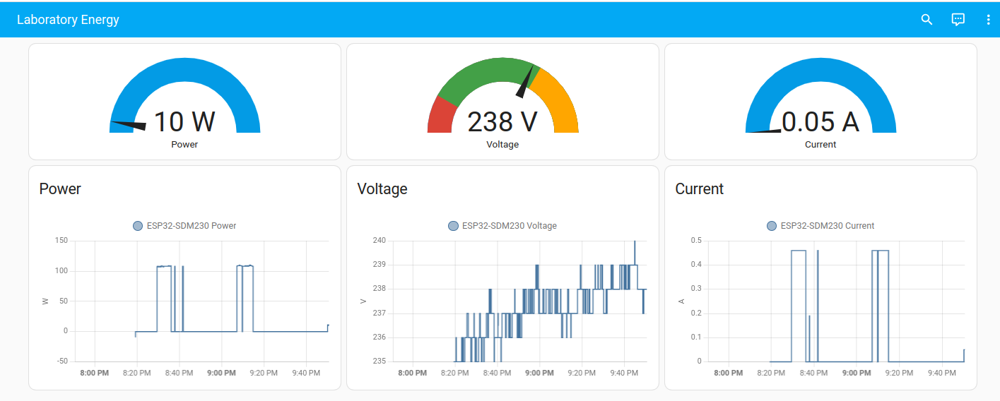
Monitor using Home Assistant / ESPHome
To experiment a different way to build a home automation monitoring system, I decided to try:
- Home Assistant as web dashboard
- ESPHome as device firmware
Home Assistant is an open-source home automation platform that allows you to control and automate smart devices in your home. It's a versatile hub for integrating various devices and creating custom automation routines.
ESPHome is an open-source framework for custom firmware on ESP8266/ESP32 devices, making it easy to integrate them into home automation.
So I installed Home Assistant in a Raspberry PI 4 following these instructions
Then I built a second ESP32 as above and installed ESPHome (instead of my custom software) on it. To do this, I started from Home Assistant, following these instructions.
Finally I bought an Eastron SDM230-ModBus Energy Meter, and I connected it to my ESP32.
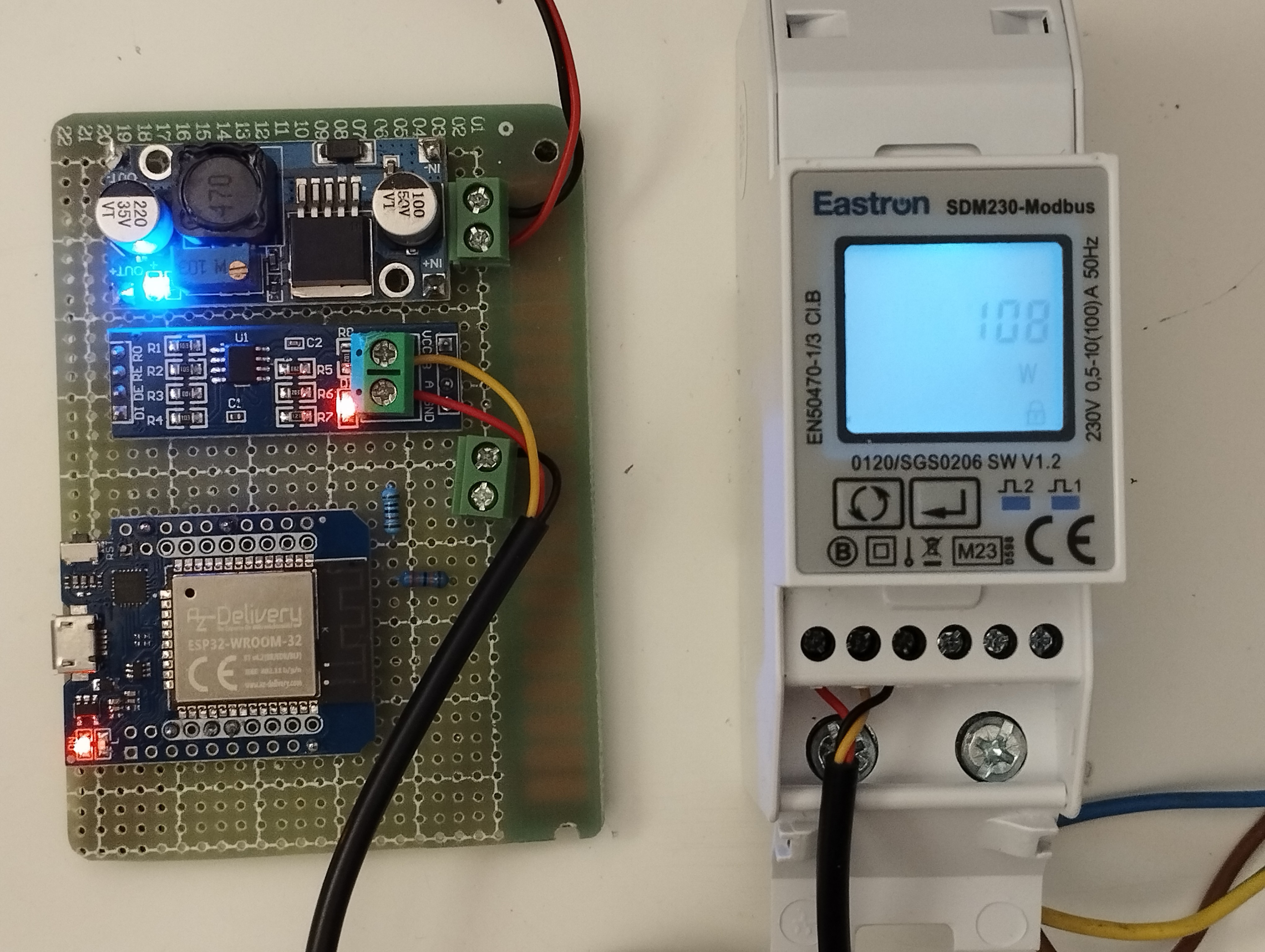
The red-yellow-black wires are the RS485 bus.
ESPHome doesn't have a ready configuration for the SDM230-ModBus, but it has the:
- uart
- modbus
- modbus_controller
- controller
which can be configured properly.
The address of each SDM230 sensor, can be obtained from the Eastron SDM230Modbus Protocol V1.2
Please note that my SDM230 (in the picture) has protocol V1.2 as is the document. Addresses for different protocol versions wouldn't work 😀
SDM230 ModBus ESPHome configuration
esphome:
  name: esp32-sdm230
  friendly_name: ESP32-SDM230

esp32:
  board: esp32dev
  framework:
    type: arduino

# Enable logging
logger:

# Enable Home Assistant API
api:
  encryption:
    key: "Nv0p/u++0gbgbdfbggfnbnmggbIsjSo3Fu+mfzJpU="

ota:
  password: "2djfgjdftory468y346y3y356jy56ya6"

wifi:
  ssid: !secret wifi_ssid
  password: !secret wifi_password

  # Enable fallback hotspot (captive portal) in case wifi connection fails
  ap:
    ssid: "Esp32-Sdm230 Fallback Hotspot"
    password: "dfg548g88g8trgr"

captive_portal:


# Example SDM-230 configuration entry
uart:
  id: mod_uart
  rx_pin: 16
  tx_pin: 17
  baud_rate: 9600 #if your energy meter is SDM230M or SDM120M than change the baud_rate: 2400
  stop_bits: 1

modbus:
  flow_control_pin: 33
  id: modbus1

modbus_controller:
  - id: sdm230
    address: 0x2   ## address of the ModBUS slave device on the bus
    modbus_id: modbus1
    update_interval: 10s
    setup_priority: -10


sensor:
  - platform: modbus_controller
    modbus_controller_id: sdm230
    name: "Voltage"
    register_type: read
    address: 0x0000
    value_type: FP32
    unit_of_measurement: V
    state_class: "measurement"
    accuracy_decimals: 0

  - platform: modbus_controller
    modbus_controller_id: sdm230
    name: "Current"
    register_type: read
    address: 0x00006
    value_type: FP32
    unit_of_measurement: A
    state_class: "measurement"
    accuracy_decimals: 2

  - platform: modbus_controller
    modbus_controller_id: sdm230
    name: "Power"
    register_type: read
    address: 0x000C
    value_type: FP32
    unit_of_measurement: W
    state_class: "measurement"
    accuracy_decimals: 0
Home Assistant Example Dashboard