Tim
Tim-
A faux-flame light bulb
11/23/2023 at 08:58 • 0 commentsNext up is a flame light bulb - the "field" has advanced quite a bit beyond the humble candle flicker LED.
![]()
I did a little experiment here: I fed the tear down photos into ChatGPT (GPT4-Turbo with Vision, assumingly) and asked to write a tear down report in the style of a hackaday.com post. I nudged it a little bit to investigate power supply and pointed to the phosphor converted LED, but the rest is as it came out.
---------- more ----------It's a bit worrysome. Enjoy:
Hacking the Faux Flame: A Teardown of the LED Bulb That Glows Like a Hearth
So you’ve seen those LED bulbs that promise a flickering flame effect? Well, we got our hands on one and decided to see what makes it tick—or should we say, flicker. It's not every day you find a bulb that doubles as an electronic fireplace, so naturally, we were intrigued.
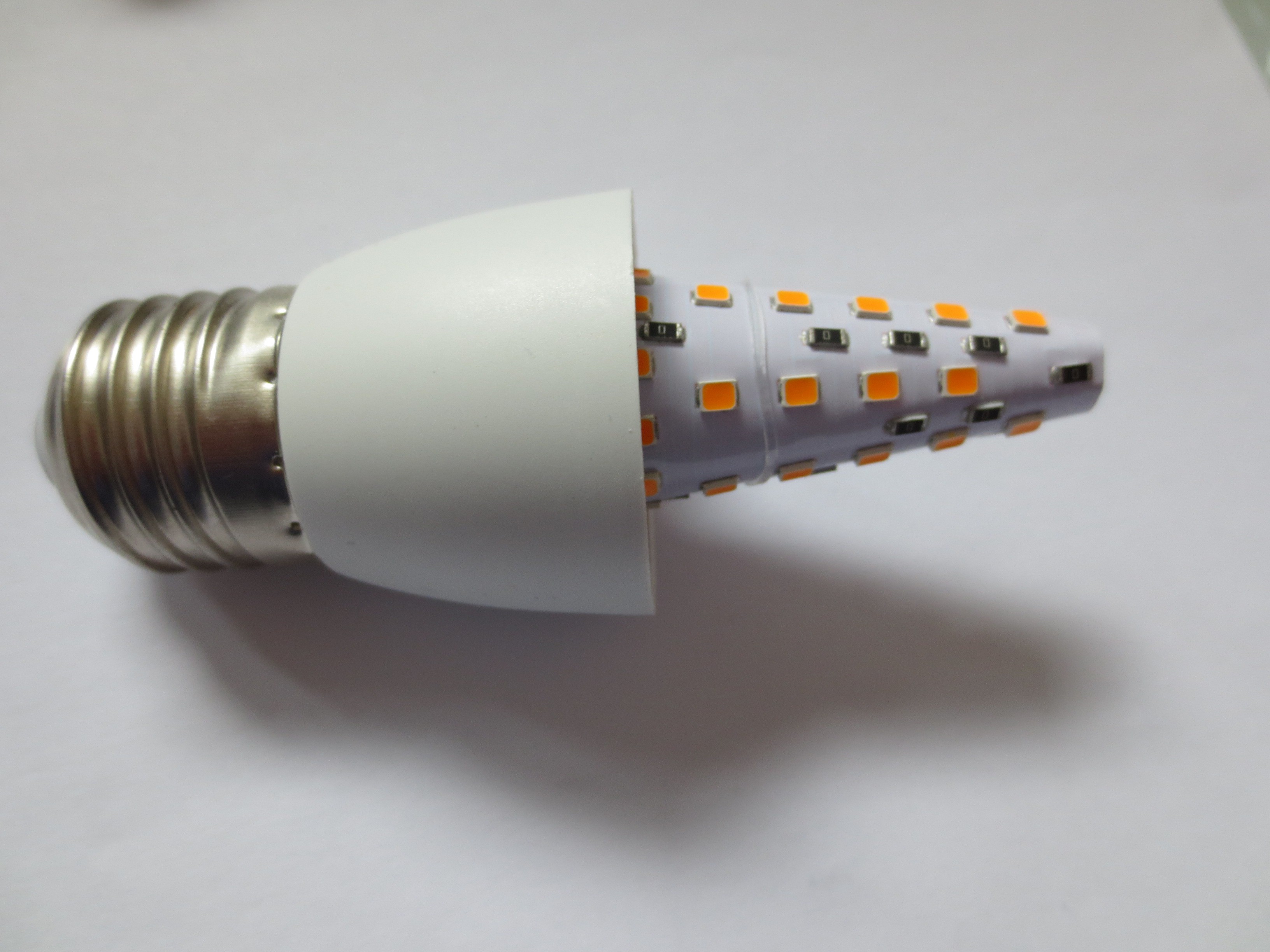
Kicking off our teardown, the first thing we did was fire it up to see the warm glow in action. It's quite the sight, and if you’re in the mood for some ambiance without the fire hazard, this bulb is your ticket. With the lights off, the LED strips are just hanging out, waiting for their chance to shine. It’s neat how something so simple can mimic the complex movement of flames.
![]()
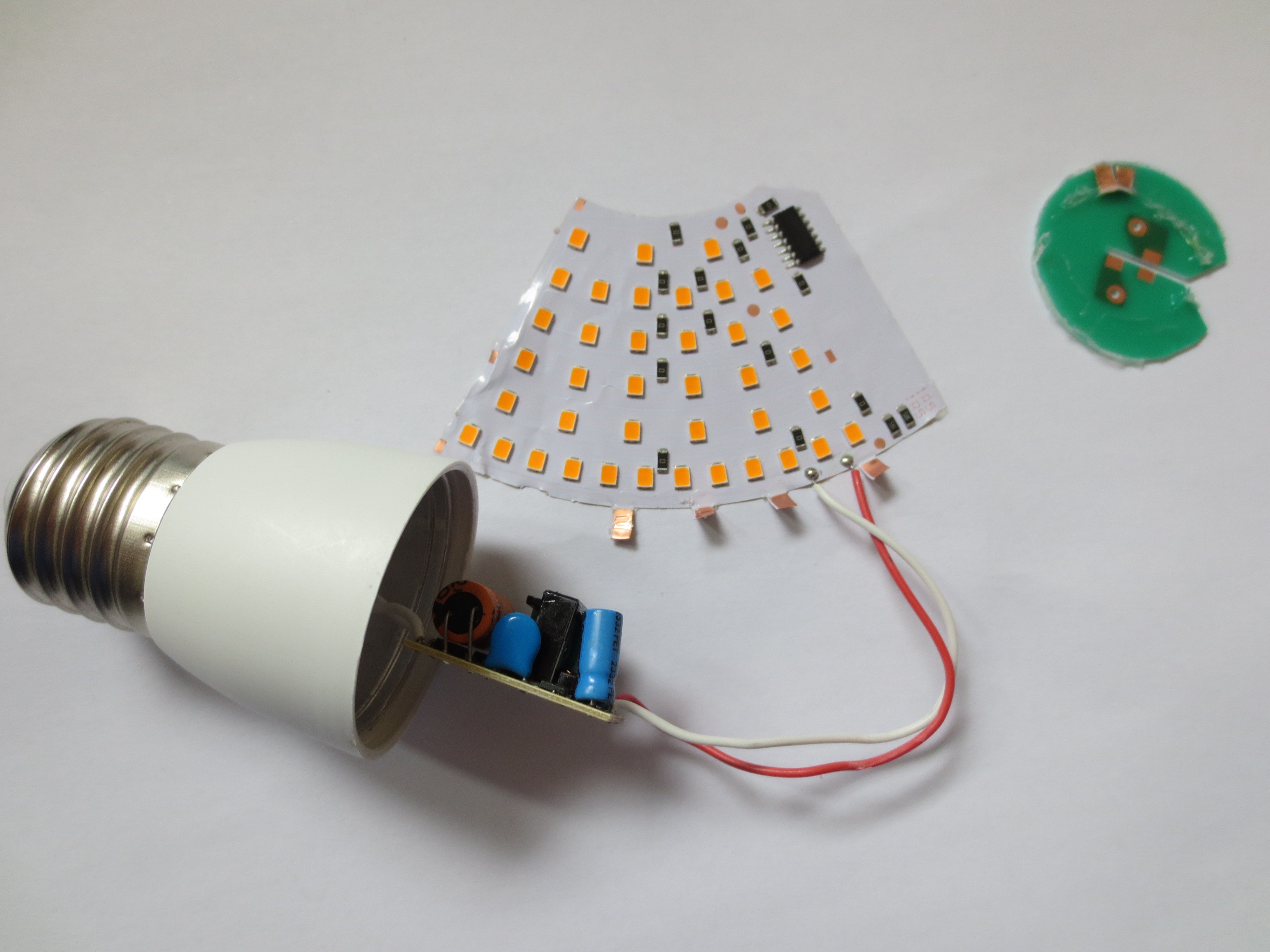
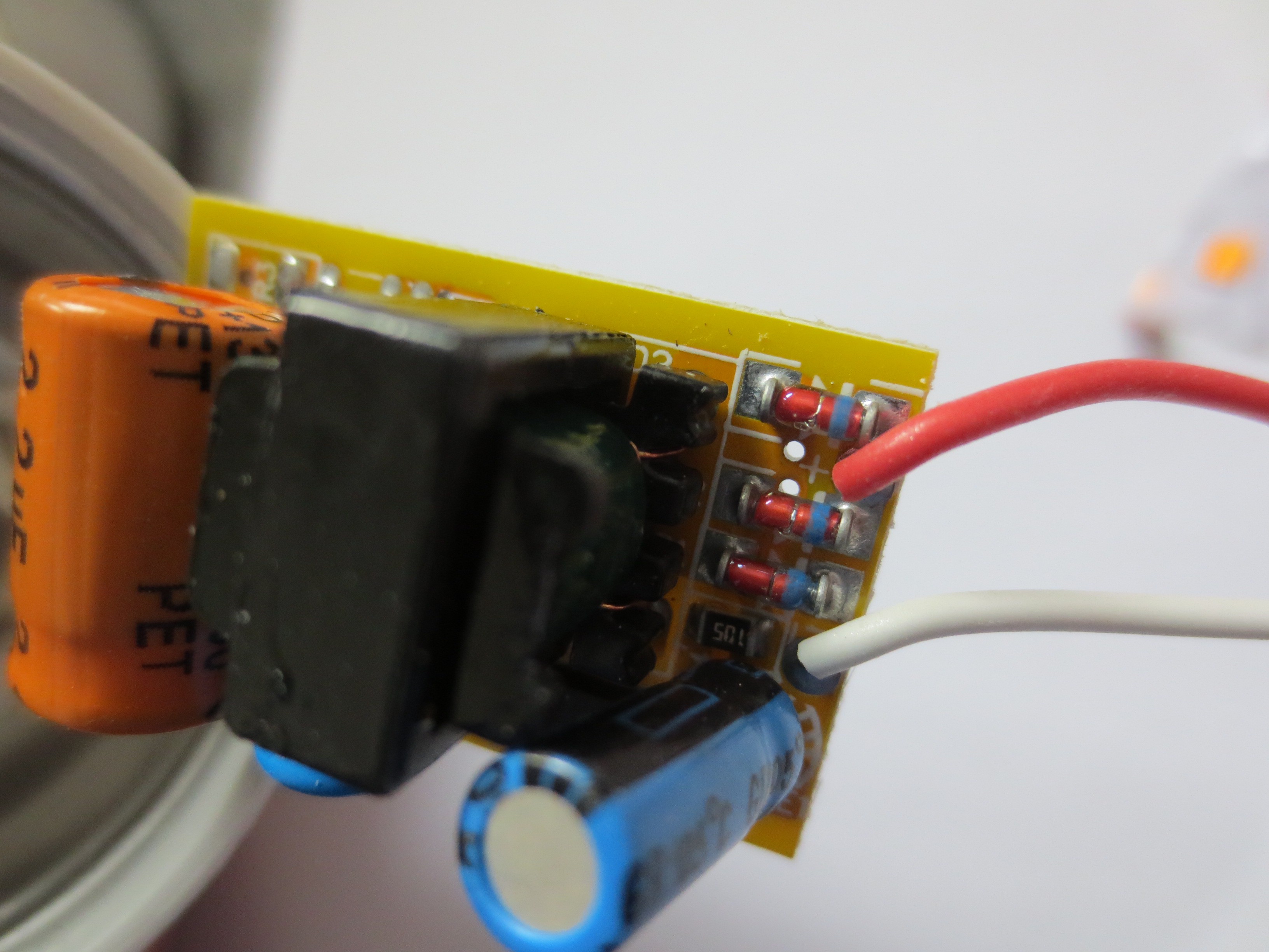
Now, diving into the guts of the gadget, we unscrewed the top and gently removed the LED strip from its housing. It felt a bit like defusing a bomb, with less risk and more anticipation. Inside, a little PCB loaded with components like capacitors and resistors was nestled snugly. This tiny board is the unsung hero, transforming your standard wall power into something these LEDs can sip on without burning out.
![]()
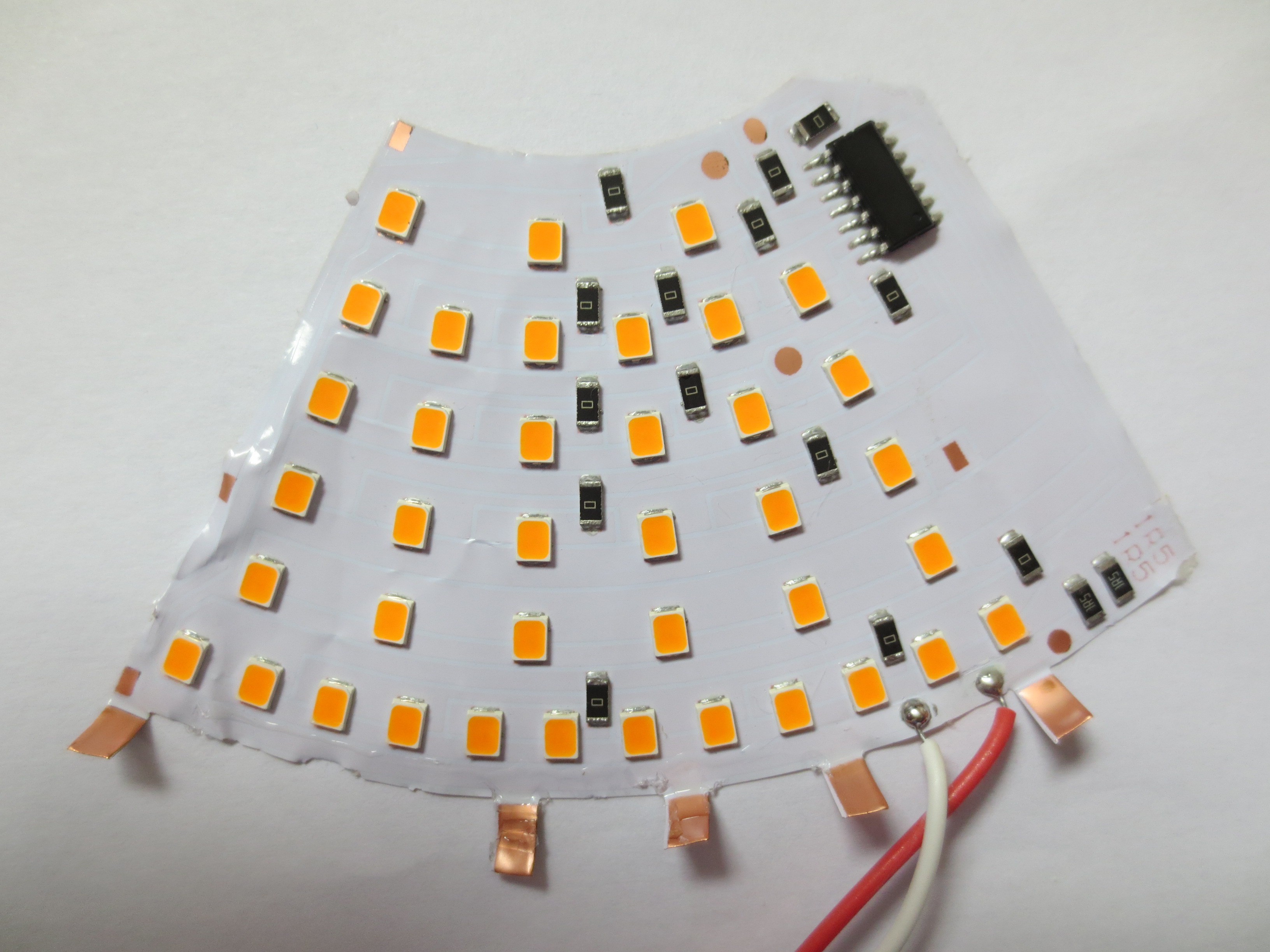
As for the LED strip itself, laid out flat, it was a miniature runway of lights, each coated with an orange phosphor for that perfect flame hue. There's an art to applying that phosphor, too—it's not just about color, but about diffusing the light in a way that gives you that soft, fire-like quality.
![]()
The star of the show is the microcontroller, a piece of silicon that conducts the light orchestra. It dictates the flickering, and it's pretty sophisticated in how it manages to replicate the random, soothing dance of a real flame.
![]()
Let’s talk power supply. This bulb has a backstage crew that would make any roadie proud. The PSU takes the AC from your outlet, runs it through a rectifier like it’s putting it through boot camp, and out comes the DC—steady and ready to rock. The capacitors are there to make sure the output is smoother than a jazz solo, ensuring the LEDs perform consistently.
![]()
Wrapping this up, tearing down the flame-effect bulb felt like a journey back to the basics of what makes LEDs so darn cool. They're not just about brightening up a room; they can set the stage, create an atmosphere, and even calm a restless mind. The design is clever, and it’s a reminder that sometimes, the simplest things can be the most delightful to hack apart and ponder.
So there you have it, fellow tinkerers, a little bit of electronic warmth to brighten up your tinkering space or your next project. It’s amazing what you can do with a few LEDs and some clever engineering.
![]()
-
Electrical Screwdriver Indicator
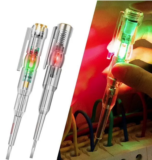
11/02/2023 at 19:30 • 0 commentsHere is a product that probably should not be sold, not even at <2 USD. As advertised, it looks like a replacement for a voltage tester or "neon screwdriver".
---------- more ----------![]() Supposedly it lights up in green if you detect ground and red of you detect the nongrounded lead of AC mains. The entire thing is extremely sensitive and the green LED even lit up when coming close to the packaged product. It seems to be a very sensitive connectivity tester, e.g. it will light up when touching both ends of the screwdriger or any grounded electrical device. The RED LED - on the other hand - did not light up under any circumstances. Highly doubtful functionality.
Supposedly it lights up in green if you detect ground and red of you detect the nongrounded lead of AC mains. The entire thing is extremely sensitive and the green LED even lit up when coming close to the packaged product. It seems to be a very sensitive connectivity tester, e.g. it will light up when touching both ends of the screwdriger or any grounded electrical device. The RED LED - on the other hand - did not light up under any circumstances. Highly doubtful functionality.![]() The image above seems to show an older revision of the product, mine was using SMD LEDs.
The image above seems to show an older revision of the product, mine was using SMD LEDs.
Photo of product
(sorry for white balance, don't think its worth the effort to fix ut)![]()
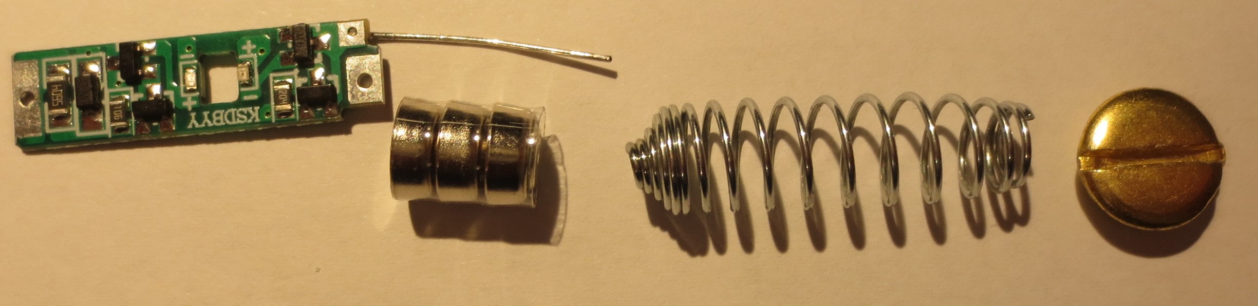
Included PCB with battery holder.
Extremely obscure and low cost construction. Both the contact to the drivers head and the battery is made by metallized PCB edges. The other pole of the battery is connect by the spring and the metal wire that sticks out. The spring also provides contact to the metallized top of the screw driver that you are support the touch.Considering that this is a product which is used to contact live circuits under mains voltage. How many things can go wrong when assembling this? Crazy.
![]()
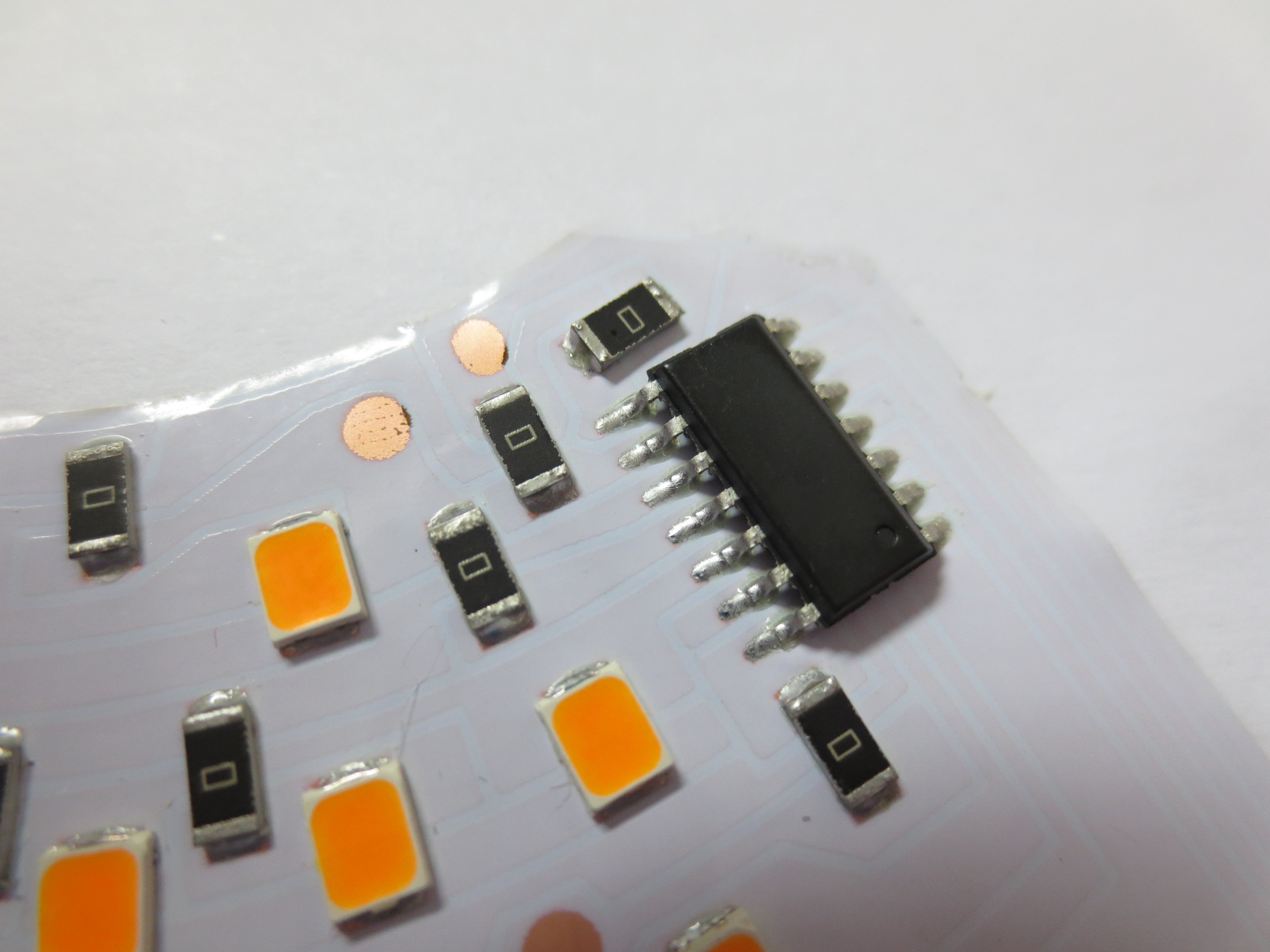
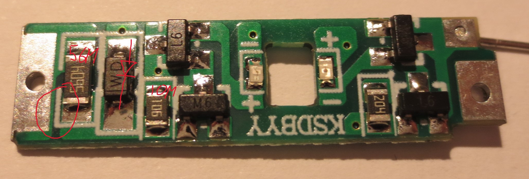
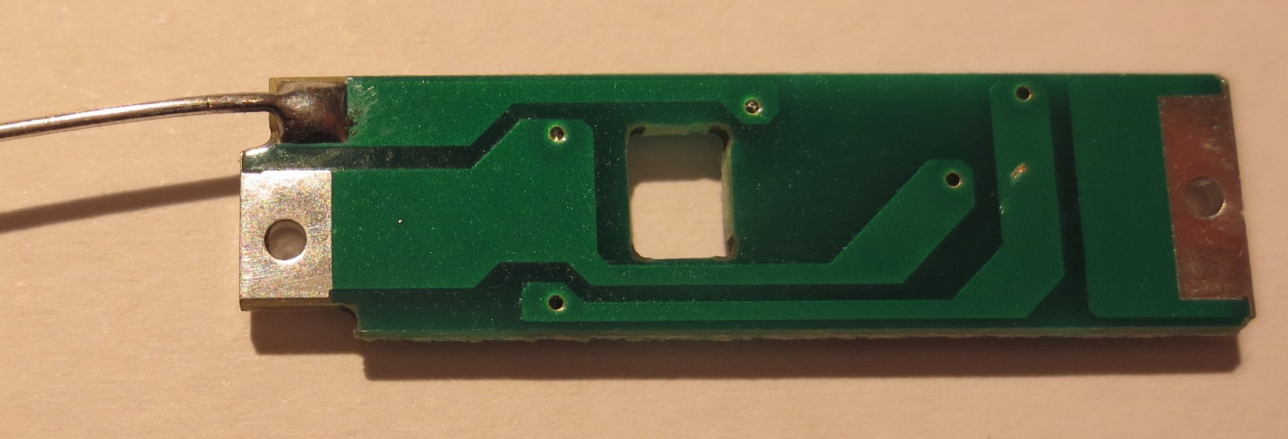
PCB top and bottom
Details of the PCB are shown below. There seem to be two NPN and two PNP transistors, according to the marking. In addition to LEDs, a few resistors and a diode. The "hot" input is protected my a 5.6 Mohm resistor. There After this resistor there seems to be one path through a diode and one path that through a 10 Mohm resistor. Possibly the circuit distinguishes AC voltage and DC conduction with the idea of detecting the hot and ground wire.The high and low voltage parts of the circuit are only separated by minimum trace spacing on the PCB. This does not really look like a safe design to me.
![]()
![]()
Potential safety hazard and lack of proper functionality. Off into the trash it goes - strong recommendation not to buy.
-
Equalizer Bar
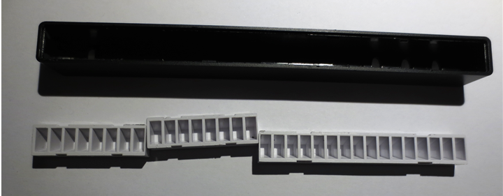
10/24/2023 at 22:03 • 0 commentsThis is a small USB power equalizer bar with an integrated microphone. Different modes and color settings can be selected with push buttons on the rear side. There is also a version with an integrated battery.
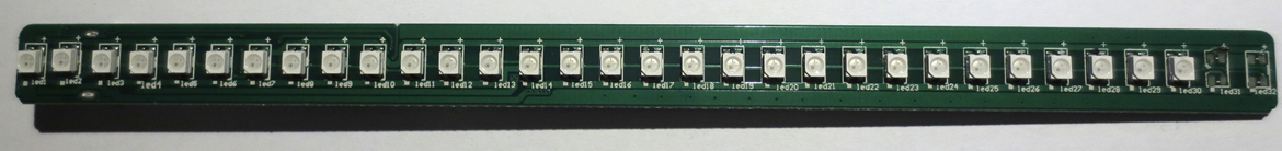
---------- more ----------The device is surprisingly well made. The PCB sits at the bottom of the casing with white light diffusing cavities on top. The bar is illuminated by 32 addressable RGB LEDs in 3528 form factor.
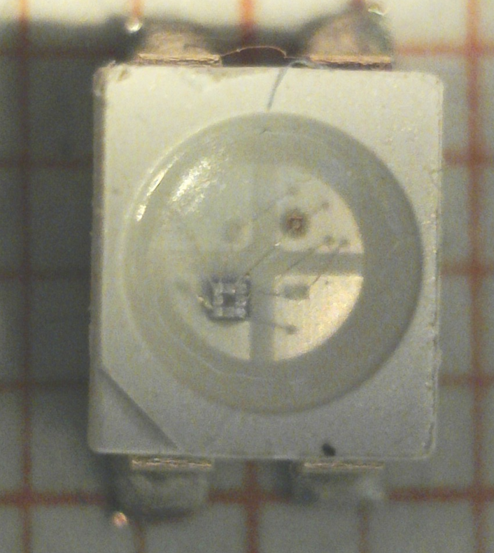
I close-up of an LED is shown above. This seems to be a "TX1812" based device, which currently seem to be the lowest cost WS2812 clones. They can be found from several "no name" suppliers.
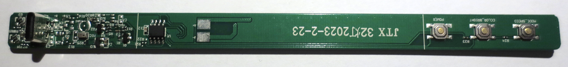
The rear side of the PCB holds push buttons and the remaining electronics.
A single 8 pin MCU without markings controls the entire device. The manual claims that it is a 32 Bit ARM based process with 72MHz clock. The microphone can be seen in the center of the image. There is a surprising amount of analog electronics, most likely to condition the microphone signal. Other than that there are a few unpopulated footprints to allow for a battery operated version.
-
Remoted Controlled RGB Light Bulb
10/23/2023 at 13:44 • 0 commentsThis isn't a high-tech Wifi, Bluetooth, or Zigbee light bulb but one that's operated with an IR remote control. I purchased it for approximately $2, including shipping. The functionality is straightforward: you can choose from sixteen colors and there are several flashy animation options. However, the dimming function appeared ineffective. I wasn't too impressed with its brightness and felt the colors appeared washed out.
![]() ---------- more ----------
---------- more ----------Remote control
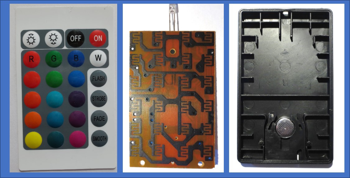
The remote control looks like those accompanying many gadgets from China, indicating a highly costomizable design. I was impressed by its cost-optimized construction.
![]()
The remote control comprises three components (from right to left):
- A molded backplate that also houses the battery.
- A PCB with circuits on one side and button contacts on the other.
- A key foil with embossed keys, designed to make contact with the button contacts when pressed
![]()
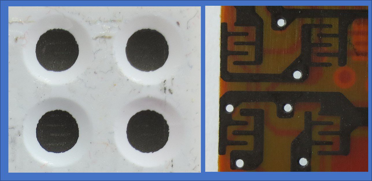
Details of the keys can be seen above. The rear of the key foil is coated with conductive ink (possibly carbon-based) and doesn't touch the PCB in its resting state due to the foil's embossing. When a key is pressed, it establishes contact with the corresponding button contact on the PCB. The PCB itself is coated with patterned conductive ink . This coating is likely carbon-based and was probably applied through screen printing.
![]()
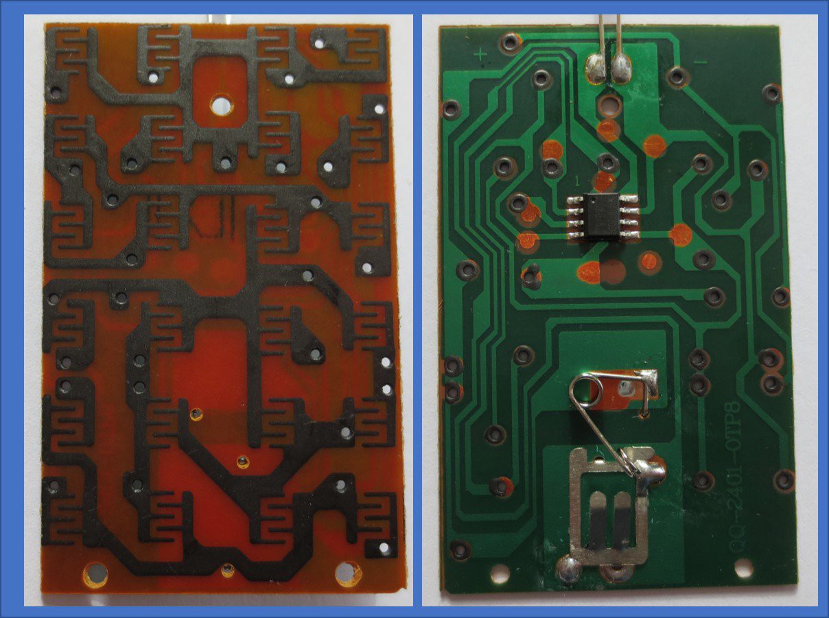
Both sides of the PCB are depicted above. The rear side features a typical copper trace PCB with solder resist, which connects to the carbon-ink through through-hole layers. What's particularly noticeable is the minimal number of components: there's a single SOIC8 IC, the infrared LED, and a battery holder.
![]()
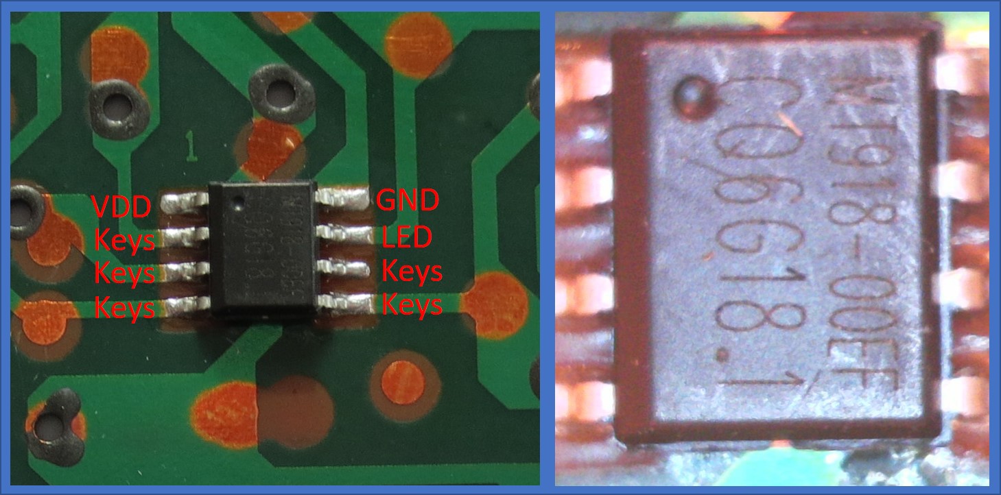
Details of the MCU are shown above. Based on the power supply pin locations, it looks like one of the ubiquitous ultra-low-cost 8bit MCUs - for example a PIC clone or Padauk MCU. Suprisingly, it does even have part marking: MT918. I have not been able to ID the supplier, though.
What is remarkable is the ability to read out 20 keys using only five pins without extra components. A matrix design would have demanded 5+4=9 I/Os. Charlieplexing would allow control over 20 keys with 5 I/Os (since n2−n=25−5=20n2−n=25−5=20) but necessitates additional diodes.
So, what's the mechanism? Initially, I hypothesized that the carbon traces might form resistive voltage dividers with an ADC for readout. While plausible, the likely inconsistent contact resistance of the switch to the pads suggests a more digital solution.
Examining the traces, it seems some keys connect to GND, others to VDD, and the rest between the key sensing pins. With five I/Os, this permits encoding 5 keys for GND, 5 for VDD, and 10 for combinations between the pins (binomial coefficient "5 choose 2" = 5! / (3! * 2!) = 10). This totals 20 keys.
The infrared LED (IRED) current is defined the GPIO driving capacity, not the nicest solution but not without precedence. I presume standard 36kHz pulse coding is employed for the IRED, demanding a fairly accurate oscillator in the MCU, likely adjusted during programming. The MCU is probably programmed directly on the PCB via the test pads.
In summary, it's a highly simplified solution, comprising just the essential components to function.
Light Bulb
The semi-transparent dome can be easily detached from the light bulb, revealing a single PCB.
![]()
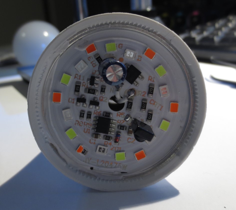
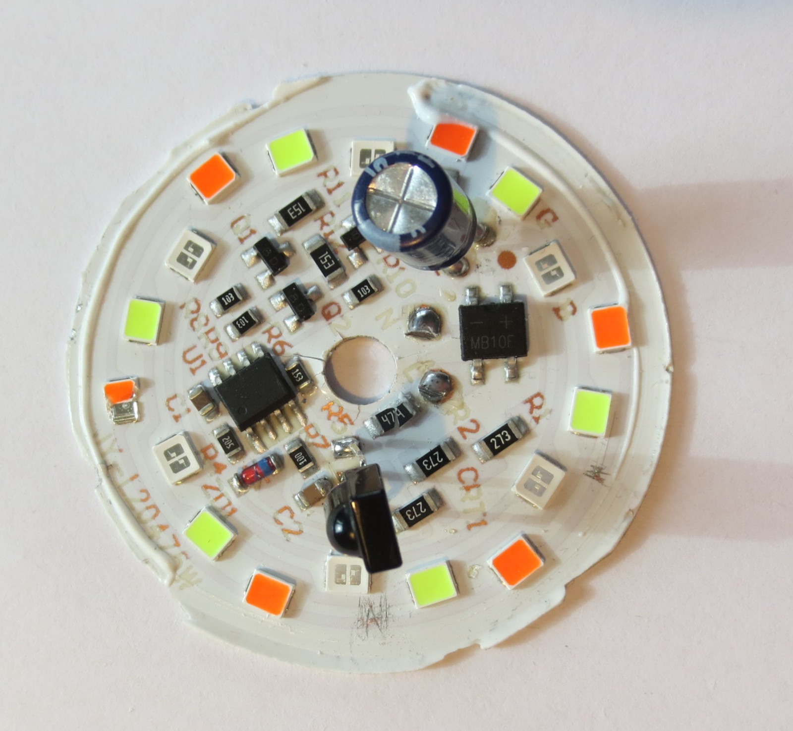
A detailed view of the PCB after its removal from the lamp socket base, although, unfortunately, some of the components were damaged in the process.
![]()
The PCB is single sided with an aluminum core. What can we see?
- There's a bridge rectifier (MB10F) that rectifies the mains current, which is 240V in this instance.
- Another SOIC8 microcontroller, unmarked this time, manages all operations.
- An IR remote control receiver is present, which receives the remote control signal.
- The supply voltage for both the MCU and the remote control receiver is stabilized using a zener diode (ZD1). Current is restrained by a resistor. It's intriguing that no LDO was employed, but perhaps the advantage of a zener diode is enhanced voltage stability, while typical LDOs can handle only a few tens of volts as input. Additional resistors and capacitors ensure current limitation and voltage stabilization.
- There appear to be three LED strings for red, green, and blue lighting. Each string seems to be regulated (switched on and off) by a transistor. Resistors provide current limitation, and a 2.2µF capacitor helps mitigate the inevitable 100Hz ripple. The LEDs' dimming is achieved via pulse width modulation (PWM).
Everything is, again, implemented with a bare minimum of components.
LEDs
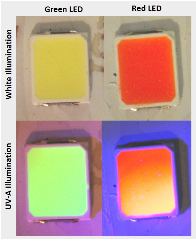
The LEDs used here are actually quite curious and are key to being able to simplify the circuit is much as it is. The first notable thing is that the blue LED are clear, while the green and red LED appear colorful.
![]()
The reason for this is that all LEDs utilize blue-emitting LED chips. The green and red LEDs employ phosphors to convert this blue light into green and red hues, respectively. As illustrated in the image above, the phosphor emits light when exposed to UV-A (as seen in the bottom row).
![]()
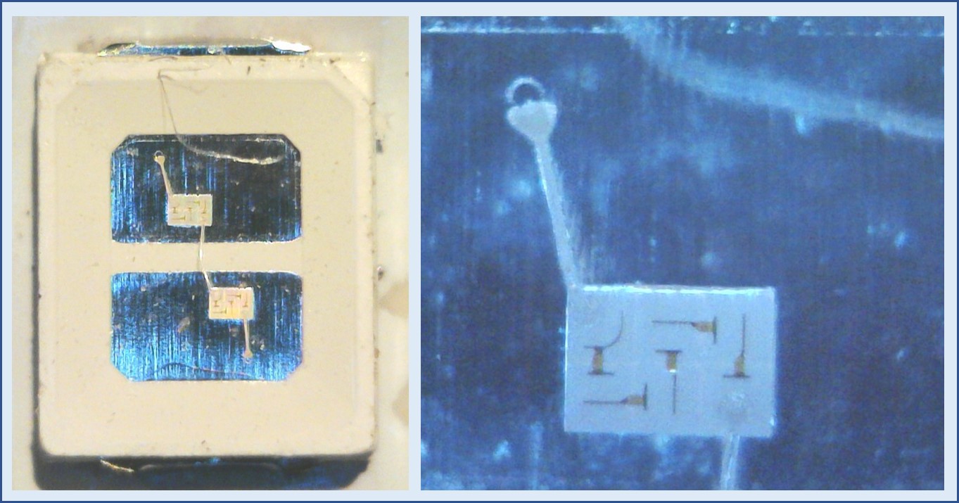
Taking a closer look at the blue LEDs reveals that each LED package actually containts two LED dies that are connected in series. The right side of the image shows a magnification of a single die - these are actually high-voltage LED dies where a number of LEDs is connected in series on a single die! (Nice youtube video explaining those).
Indeed, I had to apply more than 31 V to get one of these LEDs to emit light. This implies that the total voltage drop across a string of 6 LEDs exceeds 186V. Given that all LEDs are based on the same blue-emitting chips, the same voltage drop occurs across the red, green, or blue string.
This high voltage enables the LEDs to be powered directly from the rectified mains voltage, bypassing the need for more complex inductance-based voltage converters.
Conclusions
In conclusion, while the utility of the RGB light bulb may be limited, it is a fairly nice example of low-cost electronic optimization based on purposefully tailored components.
Dissecting Low-Cost Electronics
This is a place to dump tear downs of low-cost electronic gadgets

 Here is a product that probably should not be sold, not even at <2 USD. As advertised, it looks like a replacement for a voltage tester or "neon screwdriver".
  Supposedly it lights up in green if you detect ground and red of you detect the nongrounded lead of AC mains. The entire thing is extremely sensitive and the green LED even lit up when coming close to the packaged product. It seems to be a very sensitive connectivity tester, e.g. it will light up when touching both ends of the screwdriger or any grounded electrical device. The RED LED - on the other hand - did not light up under any circumstances. Highly doubtful functionality.
 The image above seems to show an older revision of the product, mine was using SMD LEDs.
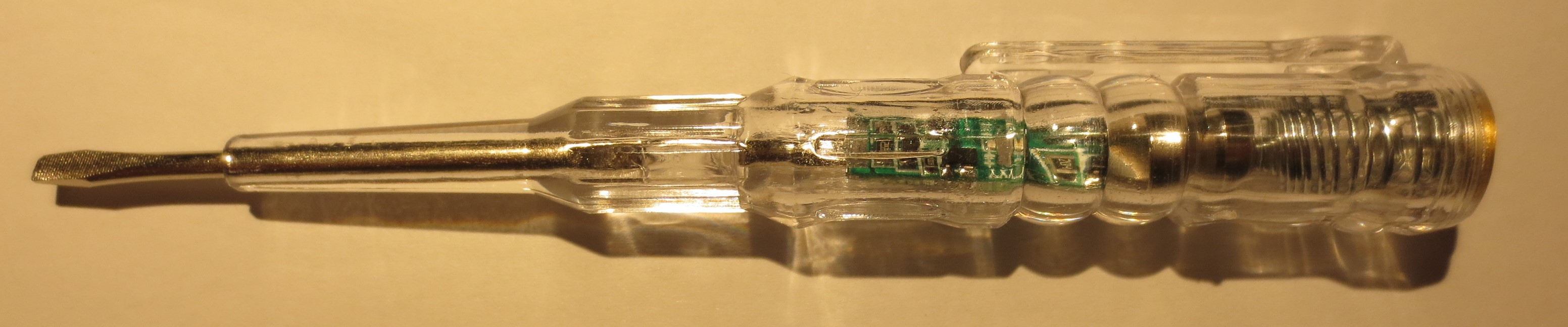

 The rear side of the PCB holds push buttons and the remaining electronics.
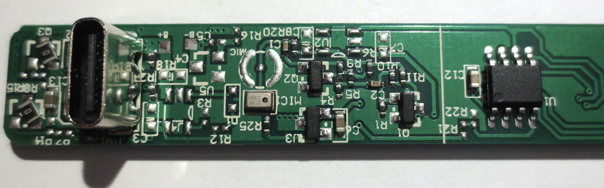 A single 8 pin MCU without markings controls the entire device. The manual claims that it is a 32 Bit ARM based process with 72MHz clock. The microphone can be seen in the center of the image. There is a surprising amount of analog electronics, most likely to condition the microphone signal. Other than that there are a few unpopulated footprints to allow for a battery operated version.