 levent erenler
Hello everyone!
Firstly, please don't make assumptions if you've come across a post similar to this one before. I'm reaching out to connect with fellow robot enthusiasts who share my passion. While I'm an engineer and creator, I'm not a writer, so I appreciate your patience and understanding. Thanks!
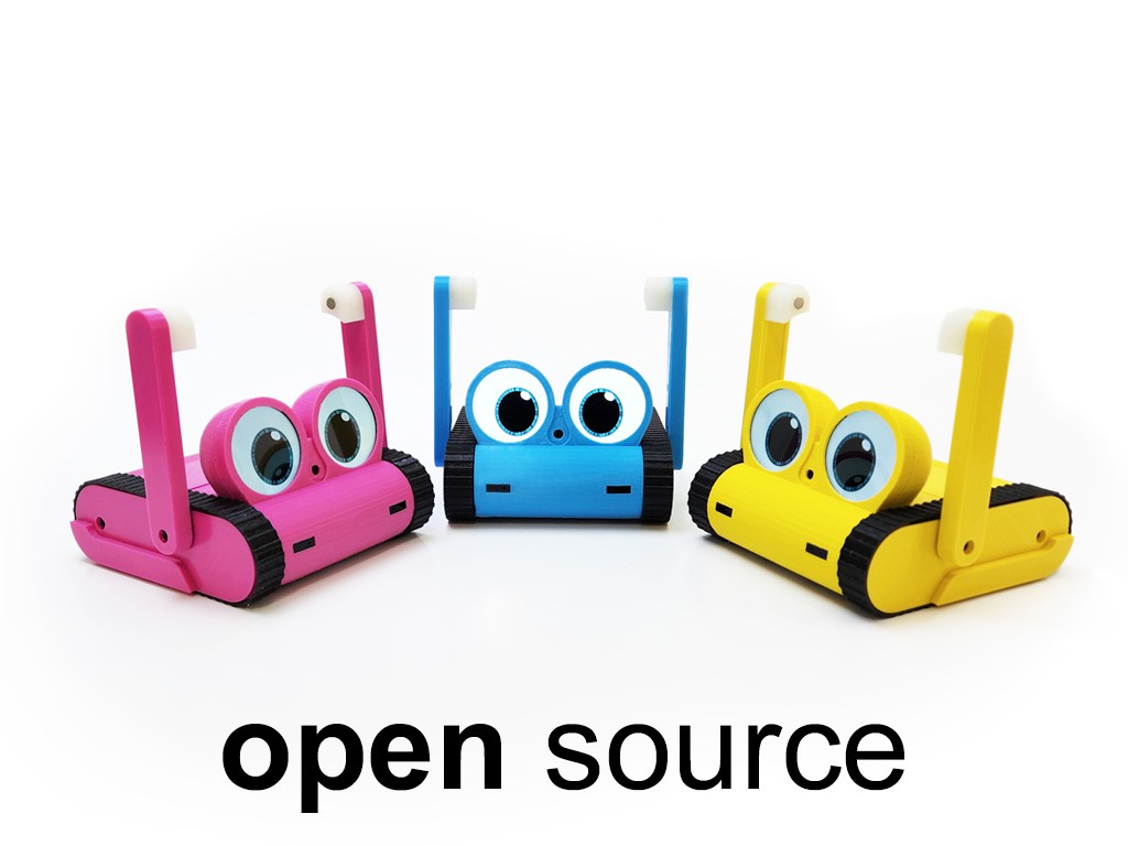
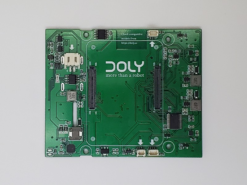
You might be familiar with the postponed Doly Kickstarter project. After launching, I received a lot of feedback. Many of them asked for additional features and more flexibility. People have different needs. Some wanted to build it themselves, others were looking for a developer platform for AI projects or other robotic features. Others were looking for a robot for their child's education or just for fun. That's why I upgraded Doly to meet all these demands. The original design was based on embedded design running Linux, but now it's based on the Raspberry Pi CM4 and it works with any CM4 with WiFi. This updated design provides more flexibility, allowing you to upgrade your hardware if you need more RAM or storage for complex projects. Plus, you now have access to hardware with 6 GPIO, 2 servos, UART, I2C and USB.
I expected the upgrade to take 4 months, but it ended up taking 6 months. During this time, I was unable to secure my CM4 orders and I kept waiting for my order. However, I used this time to work on the Open Doly project and now I'm excited to share with you how to build a robot from scratch.
On this project page, I will explain how you can build your own DIY Doly. It's a do-it-yourself project, and it doesn't come with a complete software package like Doly, as it uses non-free APIs and SDKs that don't allow for that. However, I'm working on software support for your custom robot, including control of displays, servos, sensors, and more. My goal is to provide you with all the information and support you need, including drivers, libraries, and more, to ensure your success.
I want to thank all robot lovers, makers, and DIY enthusiasts for your support and feedback. I hope this project inspires you to create something amazing and unique.
Building a robot from scratch may seem intimidating, but with the right resources and guidance, it can be a fun and rewarding experience.
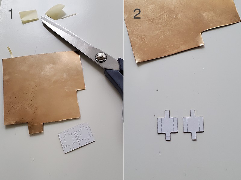
The first step is to 3D print all STL sources.
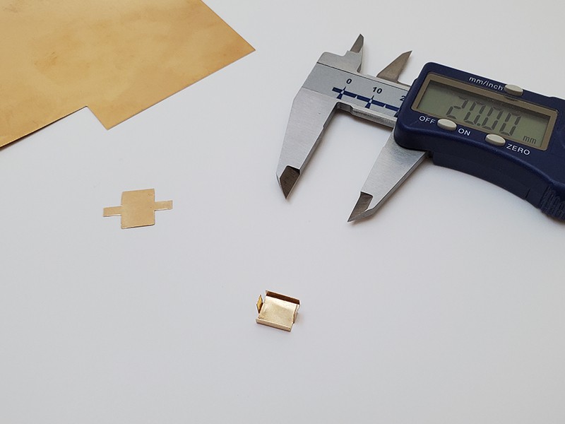
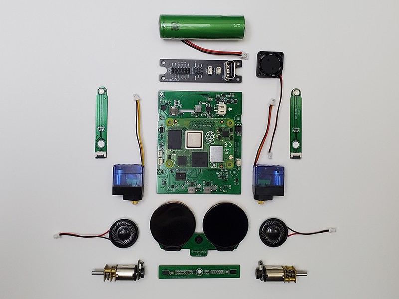
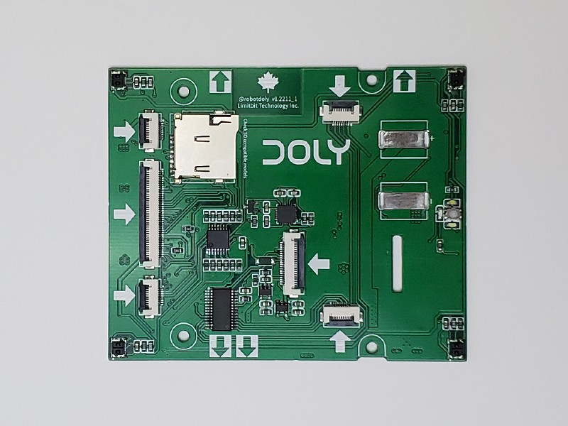
The second step is to gather the necessary materials, Raspberry Pi CM4, some electronics components, servo motors, displays and a power supply. The project documentation provides a detailed list of all the components you need.
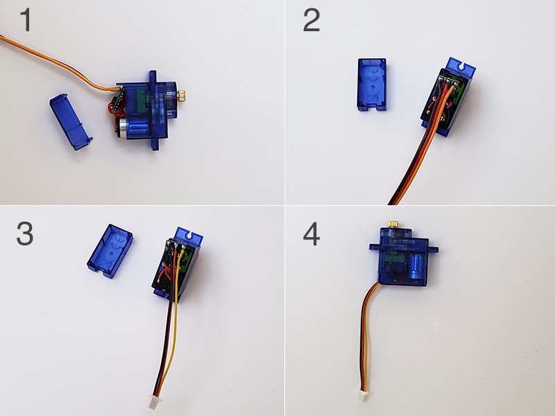
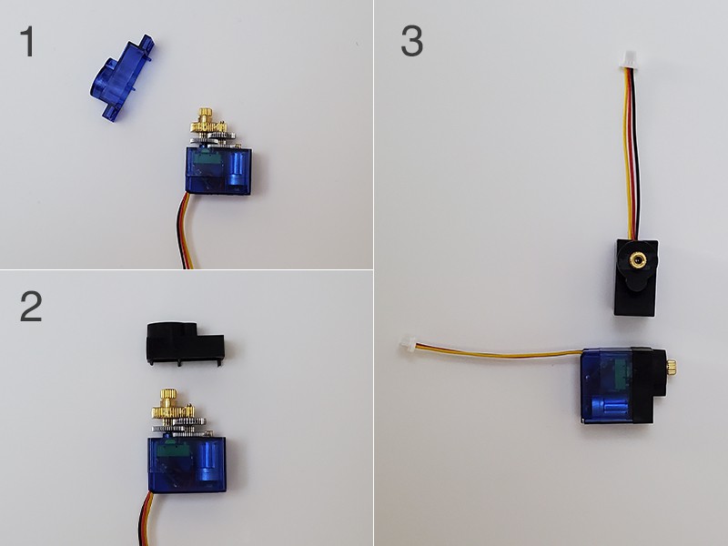
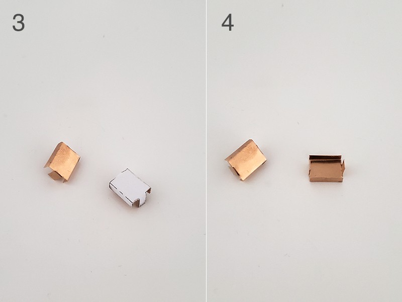
The next step is to assemble the robot following the instructions in the project details, which include schematics and all the information you need.
After assembling the robot, you can start programming it to perform various functions. The Raspberry Pi CM4 runs on Linux, making it easy to write and run code. You can use C++, Python or other programming languages to control the motors, sensors, camera and other components. The project documentation will provide a list of examples and tutorials to help you get started.
In conclusion, building your own DIY Doly can be an exciting and educational experience. You will learn about electronics, programming, and robotics, and at the end, you will have created something unique and functional. So go ahead and start building your DIY Doly today! I hope you will have as much fun and learning as I did.
Technology.
* Raspberry Pi CM4
* 8 megapixel Sony IMX219 camera
* 2x Touch sensors
* 6 Axis IMU sensor
* 2x TOF sensor
* 4x IR edge sensor
* 2x microphone
* 2x speaker
* 2x servo motor
* 2x motor with encoder
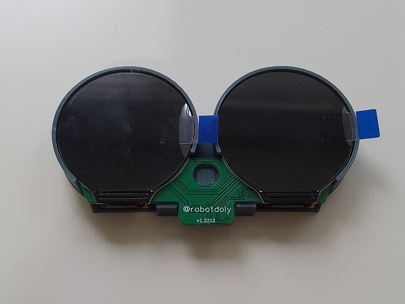
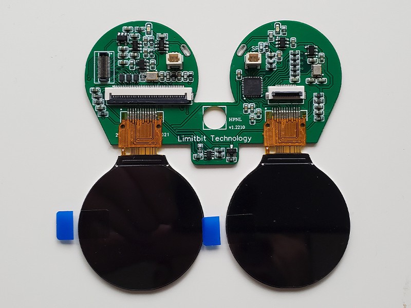
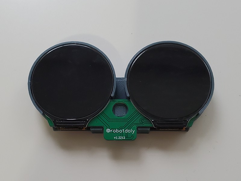
* 2x LCD Display
* 2x RGB led
* 6x GPIO pins
* 1x Qwiic / I2C port
* 1x UART port
* 1x USB output
* 2x Servo output
* 18650 battery
Possibilities with Open Doly
* Face recognition
* Speech recognition
* Object recognition
* Autonomous companion robot
* Development platform for study
* Block Based programing
* Surveillance camera
* Desktop assistant


 Dejan
Dejan
 Victor Barahona
 Doan Hong Trung
 Limenitis Reducta