 BastelBaus
This hackaday description shows I I build a full passive DIY NAS with 3x2.5GBE and >=2x4TB SSDs ("brother") to be used with its companion 2x1GBE,2x4TB SSDs (little sister) as multi home redundant cloud storage. This hayckaday describes the hardware build, the software setup can be found here (upcomming).
Please find an overview of teh components in the description andthe detailed build inside the logs.
| PC Component | Selection | ~Price (12/2023) |
|---|---|---|
| CPU+Mainboard | CPU+Board: CWWK j6413 32GB RAM: CT2K16G4SFRA32A | 175€ 80€ |
| Storage | boot: Crucial P3 500GB M.2 PCIe Gen3 NVMe
system: Crucial P3 1000GB M.2 PCIe Gen3 NVMe storage: 2x Samsung 870 QVO 4TB | 30€
60€ 360€ |
| Supply | PSU: Inter-Tech 88882190 (200 W, 20-polig, ATX)
Power Supply: Leicke 150W, 12V, 12.5A | 36€ 40€ |
| Misc | Power Buttons: Sata Cables: | 4€ 5€ |
| Total: | 790€ |
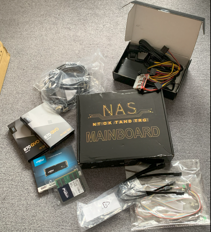
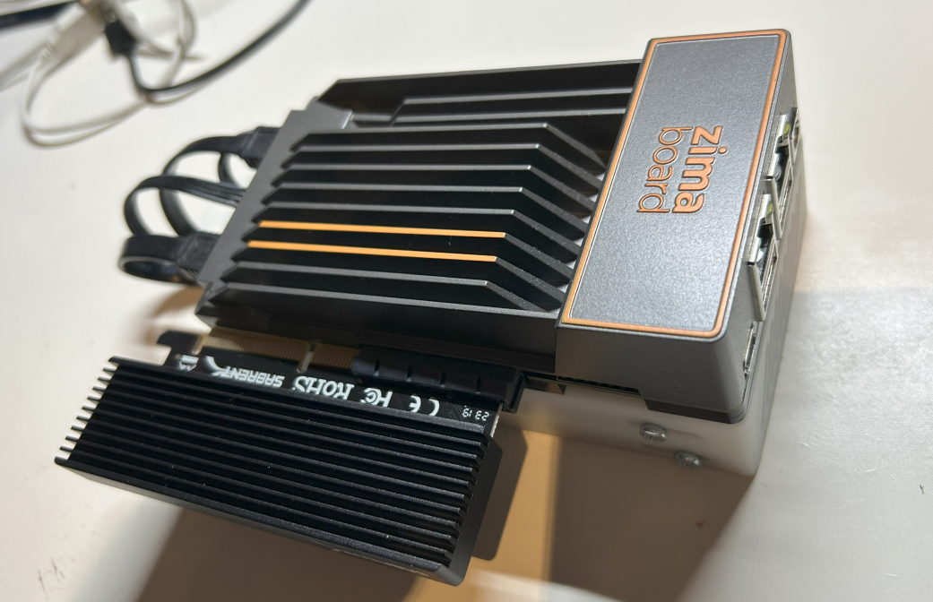
And this is how it looks when it arrives:
| Housing Componet | ~Costs (12/2023) |
|---|---|
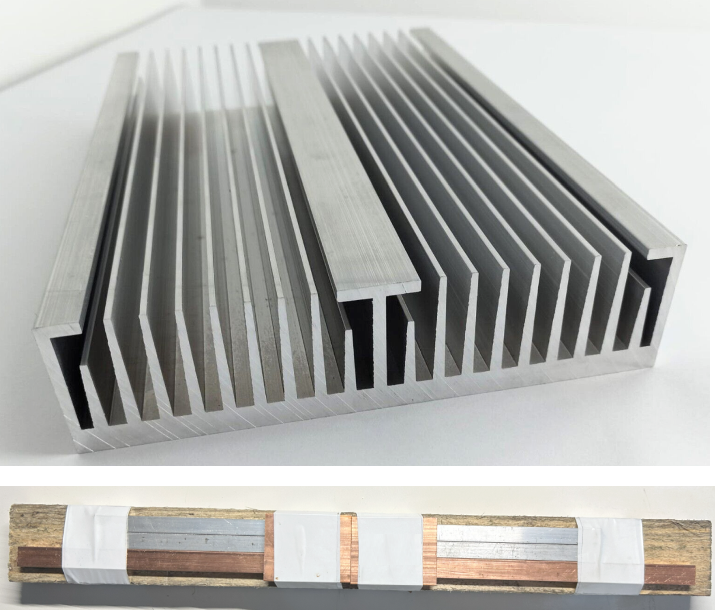
| Cooler ALU (300x200x50mm), eBay | 30€ |
| 3x pulsating heat pipe (QY-SHP-D6-200SA/6MM 200mm long) | 24€ |
| Copper Block: 2* 50x50x8mm
Copper Bar: 12x6mm, 400mm Alluminium Bar: 2*300x10x5mm | 23€
16€ 5€ |
| 2x Thermal Paste (MX4, 4g) | 8€ |
| Plexi Glas cover (300x200mm, 8mm) | scrap |
| 4x10cm Bosch Profiles 20x20mm (scrap) | scap |
| Screws | scrap |
| Wood (6mm, ~0.1m²) | scrap |
| Total | ~130€ |
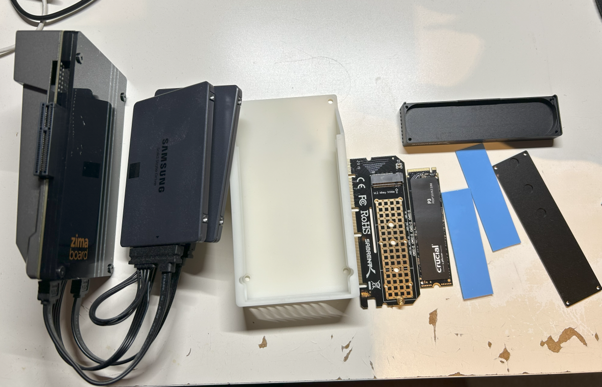
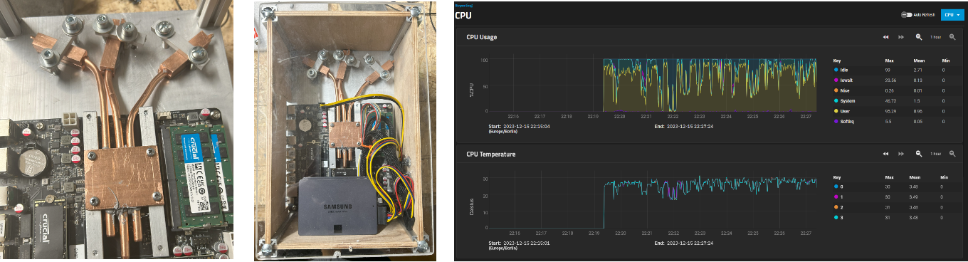
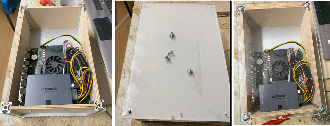
And this is how the hardware bulk looks like:
And after several build ours the beatifull result looks like this for a total cost of about 930€ (and ~100€ shipment costs, wrong orders and so on ...)
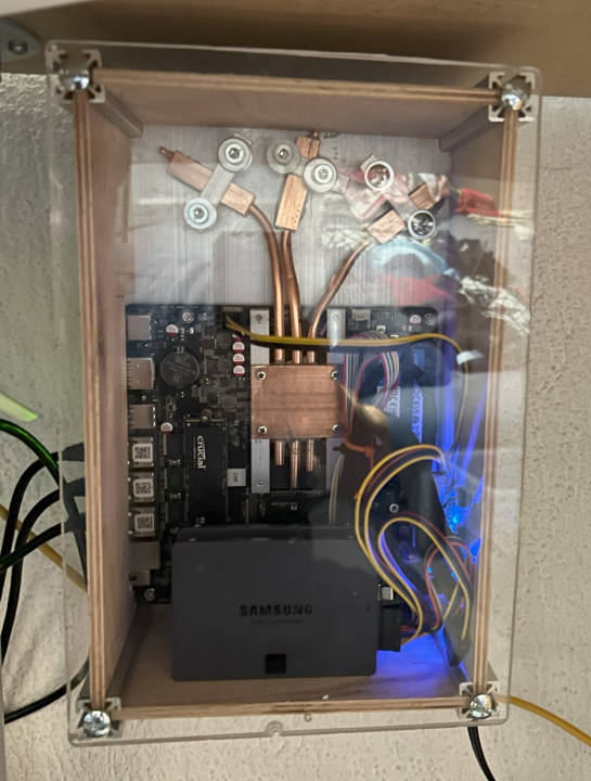
- Full passive and no moving parts, <40°C under load
- Box volume: 30x20x15cm + power supply
- Performance values:
- 12th Gen Intel Celeron 4core/4thread 1.6/3.0GHz CPU @10Watt TDP
- 4TB mirrored SD storage, 1GB application store
- 3x 2.5GBIT Ethernet
- 32GB RAM
- 930€ and a lot of build fun!
For the little sister see the last project log.
 So overall not the cheapest build but I am quite happy with the sice, the zero noise and the good performance!
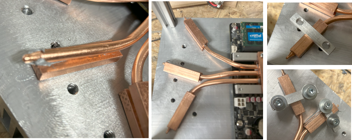
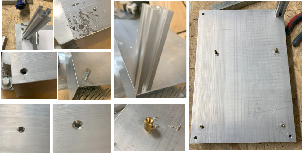
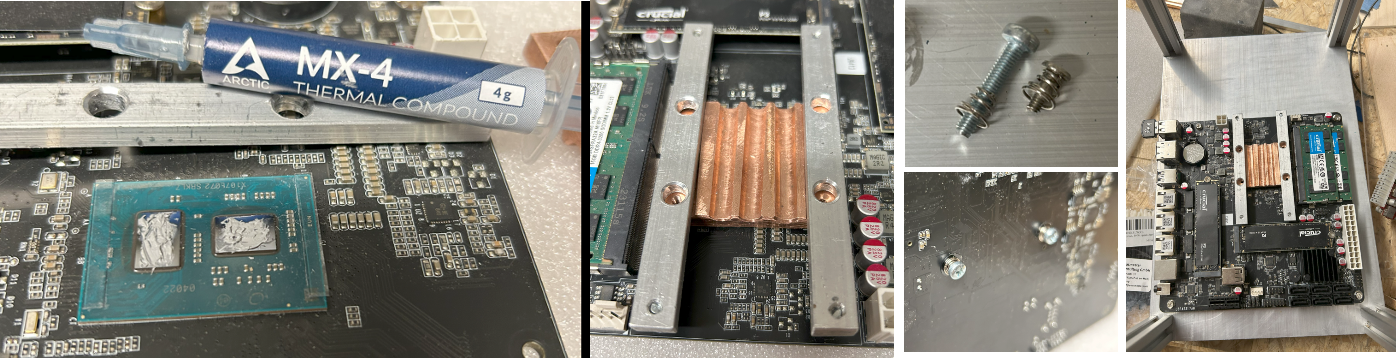 Then after experimenting with the position of the heat pipe connections to the alluminium cooler, I drilled threaded holes to mount the copper blocks to the cooler. To bend the pipes I re-used the
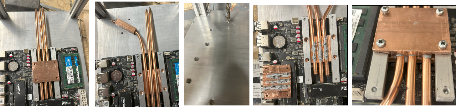
 My initial plan was to mill the upper and lower copper blocks at ones with my quite simple 18x30 CNC but this significantly failed this time (it worked not to bad for my
 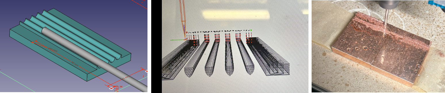 Since I had only milled about 1 or 2 mills when I gave up my initial plan, I used the same copper blockes, drilled holes (and threads) and mounted them together. Then with a good 6mm drill bit I drilled 3 holes. From my past experiences I knew that it was important to fix the copper blocks quite tightly together before drilling a hole in the interface of both.
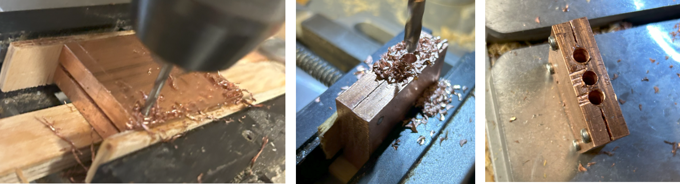 Then it was quite some manual effort to create space for the alluminium mounting brackets by first filing and finally using a metal saw.
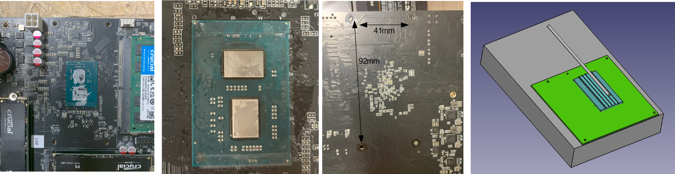
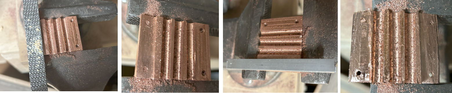 I drilled holes and threads in the alluminium mounting brackets and sanded the copper bottom to be mounted to the bare die CPU chips.
 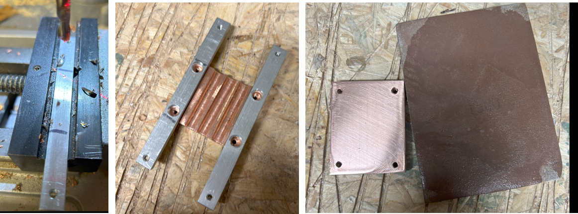 Finally I cut 6 copper bars, clammed them very tightly together and drilled three holes into them. And yes, I did not take care enough to drill the hole very straight but this should not harm the function.
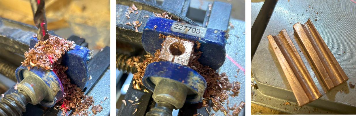
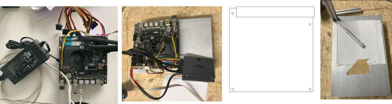
 To mount the housing on the wall, I just cutted to holes in the alluminium cooler. For the sides I used 6mm thick scrap wood which fits perfectly between the profiles. For the power connection, the LEDs and the on/off button I drilled small holes in the side and fixed them by hot glue.
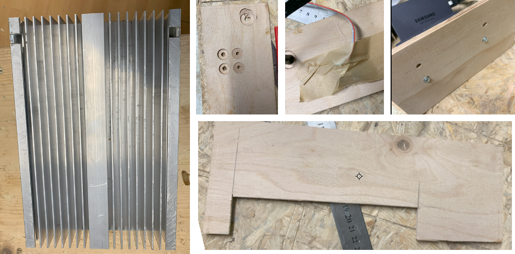
 Julianne
 Raymond
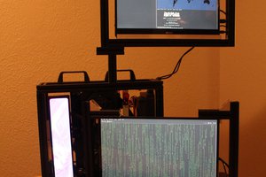
 Jonathan Kinnard
 Dominic11112